Permeable Membrane Microchannel Heat Sinks And Methods Of Making
Collins; Ivel Lee ; et al.
U.S. patent application number 16/421950 was filed with the patent office on 2019-11-28 for permeable membrane microchannel heat sinks and methods of making. The applicant listed for this patent is Purdue Research Foundation. Invention is credited to Ivel Lee Collins, Suresh V. Garimella, Liang Pan, Justin A. Weibel.
| Application Number | 20190360759 16/421950 |
| Document ID | / |
| Family ID | 68614370 |
| Filed Date | 2019-11-28 |


View All Diagrams
| United States Patent Application | 20190360759 |
| Kind Code | A1 |
| Collins; Ivel Lee ; et al. | November 28, 2019 |
PERMEABLE MEMBRANE MICROCHANNEL HEAT SINKS AND METHODS OF MAKING
Abstract
Permeable membrane microchannel heat sinks and methods of producing such a heat sink, wherein such a heat sink includes a base and at least first and second microchannels defined by at least one porous and permeable membrane that is on the base and defines primary heat exchange surfaces of the heat sink. The membrane has opposing faces exposed to the first and second microchannels, and a fluid flowing through the heat sink flows from the first microchannel to the second microchannel through pores in the membrane.
| Inventors: | Collins; Ivel Lee; (West Lafayette, IN) ; Weibel; Justin A.; (West Lafayette, IN) ; Pan; Liang; (West Lafayette, IN) ; Garimella; Suresh V.; (West Lafayette, IN) | ||||||||||
| Applicant: |
|
||||||||||
|---|---|---|---|---|---|---|---|---|---|---|---|
| Family ID: | 68614370 | ||||||||||
| Appl. No.: | 16/421950 | ||||||||||
| Filed: | May 24, 2019 |
Related U.S. Patent Documents
| Application Number | Filing Date | Patent Number | ||
|---|---|---|---|---|
| 62676494 | May 25, 2018 | |||
| Current U.S. Class: | 1/1 |
| Current CPC Class: | B22F 3/1055 20130101; B33Y 80/00 20141201; F28D 2015/0225 20130101; F28D 15/02 20130101; F28F 3/12 20130101; F28F 2260/02 20130101; H01L 23/473 20130101; B22F 5/10 20130101 |
| International Class: | F28D 15/02 20060101 F28D015/02; F28F 3/12 20060101 F28F003/12 |
Claims
1. A heat sink comprising a base and at least first and second microchannels defined by at least one porous and permeable membrane that is on the base and defines primary heat exchange surfaces of the heat sink, the membrane having opposing faces exposed to the first and second microchannels, and an entirety of a fluid flowing through the first microchannel flows from the first microchannel to the second microchannel through pores in the membrane therebetween.
2. The heat sink of claim 1, wherein the membrane has a nonlinear horizontal profile.
3. The heat sink of claim 2, wherein the nonlinear horizontal profile of the membrane approximates a sine wave.
4. The heat sink of claim 1, wherein the membrane has a nonlinear vertical profile.
5. The heat sink of claim 4, wherein the membrane is not perpendicular to the base.
6. The heat sink of claim 1, further comprising at least one fluid inlet fluidically connected to at least the first microchannel and at least one fluid outlet fluidically connected to at least the second microchannel.
7. The heat sink of claim 6, wherein the inlet is fluidically connected to only the first microchannel.
8. The heat sink of claim 6, wherein the inlet is fluidically connected to the first microchannel and at least another microchannel of the heat sink.
9. The heat sink of claim 6, wherein the outlet is fluidically connected to only the second microchannel.
10. The heat sink of claim 6, wherein the outlet is fluidically connected to the second microchannel and at least another microchannel of the heat sink.
11. The heat sink of claim 1, wherein the first and second microchannels define flowpaths that are parallel to each other.
12. The heat sink of claim 1, wherein the first and second microchannels and the membrane are disposed in a single tier on the base and the membrane is contiguous with and projects away from the base.
13. The heat sink of claim 1, further comprising an electronic device in thermal contact with the base of the heat sink, and the fluid is flowing through the heat sink to absorb and transfer heat from the source by conductive heat transfer from the source to the membrane and then convective heat transfer from the membrane to the fluid.
14. A method of fabricating the heat sink of claim 1, the method comprising an additive manufacturing technology.
15. The method of claim 14, wherein the additive manufacturing technology comprises direct metal laser sintering.
Description
CROSS-REFERENCE TO RELATED APPLICATIONS
[0001] This application claims the benefit of U.S. Provisional Application No. 62/676,494, filed May 25, 2018, the contents of which are incorporated herein by reference.
BACKGROUND OF THE INVENTION
[0002] The present invention generally relates to heat transfer devices and methods. The invention particularly relates to permeable membrane microchannel (PMM) heat sinks having complex and thin porous internal structures capable of exhibiting relatively low pressure drops, and methods of producing such heat sinks.
[0003] The pursuit for higher power and more compact electronics in aerospace, automotive, and other applications requires complimentary thermal management technologies that can effectively remove large amounts of heat within a small envelope. Microchannel heat sinks are known in the art as capable of high-heat-flux cooling with low thermal resistance, and therefore suitable for removing dense heat loads from high-power electronic devices. Microchannel heat sinks have been extensively studied for a range of working fluids in both single- and two-phase operation. A nonlimiting example of a microchannel heat sink is schematically represented in FIG. 1 as comprising headers to distribute fluid flow among multiple parallel microchannels. While straight channels having a rectangular cross section are common, other cross-sectional shapes (e.g., circular, triangular, trapezoidal) have been investigated. Non-linear channels have also been investigated both numerically and experimentally, for example, wavy channels that can increase heat transfer at the cost of a higher pressure drop. Indeed, the high pressure drop associated with flow through the small channels in microchannel heat sinks is a primary drawback, and numerous design concepts have been proposed to address this issue.
[0004] A well-recognized and effective method of reducing the pressure drop across a microchannel heat sink is through the addition of a separate manifold layer to shorten the flow length through individual microchannels. A nonlimiting example of a manifold microchannel (MMC) heat sink is schematically represented in FIG. 2 as comprising a heat transfer layer that contains multiple parallel microchannels and a separate manifold layer for distributing fluid flow among the microchannels. Experimental studies have shown that MMC heat sinks are capable of dissipating heat fluxes in excess of 1 kW/cm.sup.2. The geometry of MMC heat sinks has been optimized for several different performance objectives, with the optimized designs improving surface temperature uniformity and reducing the thermal resistance of the heat sink at a fixed pumping power compared to a standard microchannel heat sink without a manifold.
[0005] Aside from the addition of a manifold, attempts have been made to improve the performance of microchannel heat sinks by incorporating porous features. The use of a porous medium that simply occupies the entire microchannel cross-section has been shown to provide excellent heat transfer performance, albeit at the cost of a drastically increased pumping power requirements. Numerical investigations of porous media within microchannels have found that a porous layer on the walls of a microchannel offer a desirable balance between increased thermal performance and higher pressure drop. In addition, simulations to assess the performance of a straight microchannel design utilizing porous fins between the channels instead of conventional solid walls have indicated a slight increase in thermal resistance that was offset by a significant reduction in pressure drop. This decrease in pressure drop has been attributed to the effectively non-zero `slip` fluid velocity at the wall of the porous fin. Other research has considered wavy channels. In addition to the pressure drop reduction offered by the porous fins, wavy channels are capable of reducing the thermal resistance as a result of a longer effective flow length, mixing due to vortices, and forced permeation of a portion of the fluid through the fins. However, while these numerical modeling efforts indicated the potential improvement that these increasingly complex designs may offer, fabrication of such heat sinks via conventional subtractive manufacturing techniques (e.g., micromachining, anisotropic chemical etching) is difficult if not impossible. The complexity of structures with internal porosity have been limited to features that can be produced by sintering particles in a mold.
[0006] More recently, advances in additive manufacturing (AM) technologies have enabled the fabrication of more complex geometry than previously possible with subtractive manufacturing. However, there has been little focus to date on leveraging these fabrication capabilities to enhance the performance of microchannel heat sinks for electronics cooling. Work that has studied microscale heat exchangers made by additive manufacturing, specifically powder bed fusion processes, frequently highlights issues associated with material properties and high surface roughness. I. L. Collins, J. A. Weibel, L. Pan, and S. V. Garimella, "Evaluation of Additively Manufactured Microchannel Heat Sinks," IEEE Trans. Compon. Packag. Manuf. Technol. (2018), demonstrated AM fabrication of straight microchannel and manifold microchannel heat sinks in an aluminum alloy having channel hydraulic diameters of 500 .mu.m and a monolithic construction. The pressure drop was well-predicted by conventional hydrodynamic theory, albeit with a roughness-induced early transition to turbulence at low Reynolds numbers (Re<800). The thermal performance was over-predicted, attributed to uncertainty in the thermal conductivity of the material.
[0007] Others have experimentally tested additively manufactured wavy microchannels having numerically optimized designs, with results indicating that wall roughness introduced by AM processes assisted in augmenting the heat transfer, while also contributing to an increase in pressure drop. Designs optimized for minimum pressure drop were hampered by this roughness and did not meet the performance expectations, but designs that strived for both pressure drop reduction and heat transfer augmentation via the optimization scheme yielded improved performance compared to the baseline wavy channels having rectangular cross-sections. Pin fin heat exchangers have also been studied experimentally, with results indicating that the geometric print fidelity and surface roughness had large effects on performance. Accurate production of sharp-edged solid features below 0.5 mm has been difficult or impossible.
[0008] Research on the fabrication of additively produced porous media, primarily non-stochastic lattice structures, has been conducted. These structures have been produced with powder bed fusion processes in several available metals with porosities of about 30 to about 90%. In addition to heat exchangers, these structures have been considered desirable for filtration applications. Literature regarding the intentional introduction of stochastic porosity within parts fabricated with powder bed fusion processes is relatively rare, as this is generally an undesired result and significant efforts are commonly made to eliminate porosity in nominally solid parts. Nevertheless, stochastic porosities of up to about 45% have been reported in aluminum and titanium alloys. Porosities are generally induced by varying the process parameters, including hatch spacing (the distance between adjacent laser passes) and the scanning speed.
[0009] While the study of additively manufactured microscale heat exchangers is relatively new, there have been a few demonstrations that exhibit the novel and complex heat exchanger designs that this fabrication approach enables. As an example, topological optimization has been used to generate heat sink geometries for an air-cooled jet impingement application that was then produced using powder bed fusion in an aluminum alloy. The additively produced design was compared to several conventional designs, achieving an improved coefficient of performance even when compared to heat sinks made of a higher thermal conductivity material. Others have utilized an electrochemical fabrication additive process to produce a prototype hybrid heat sink that incorporates both jet impingement and microchannel flows. Simulations have been reported indicating the superiority of the design compared with other microchannel concepts, with the designed geometry addressing several concerns normally associated with jet arrays such as wall jet formation, cross-flow, and even flow distribution.
BRIEF DESCRIPTION OF THE INVENTION
[0010] The present invention provides permeable membrane microchannel (PMM) heat sinks and methods of producing such heat sink, wherein the heat sinks have complex and thin porous internal structures capable of exhibiting relatively low pressure drops. The heat sinks are capable of exploiting the capabilities of direct metal laser sintering (DMLS) to produce the complex and thin porous features to mitigate pressure drops commonly associated with the use of porous materials for heat exchange.
[0011] According to one aspect of the invention, a permeable membrane microchannel (PMM) heat sink includes a base and at least first and second microchannels defined by at least one porous and permeable membrane that is on the base and defines primary heat exchange surfaces of the heat sink. The membrane has opposing faces exposed to the first and second microchannels, and a fluid flowing through the heat sink flows from the first microchannel to the second microchannel through pores in the membrane.
[0012] According to another aspect of the invention, a method of fabricating a permeable membrane microchannel heat sink includes an additive manufacturing technology.
[0013] Other aspects of the invention include methods of removing dense heat loads from high-power electronic devices using a permeable membrane microchannel heat sink comprising the elements described above, and high-power electronic devices equipped with a permeable membrane microchannel heat sink comprising the elements described above.
[0014] Technical aspects of the heat sinks described above preferably include the ability to incorporate complex, non-linear structures having internal porosity to enhance heat transfer and reduce pressure drop as compared to a manifold microchannel heat sink. Such heat sinks preferably utilize one or more porous walls as their primary heat transfer surface(s) and are capable of increasing the amount of surface area available for heat transfer while not requiring an increase in the volume of the heat sink, for example, as would result if the heat sinks required the use of manifolds to route fluid to their heat transfer surface(s). Heat sinks with these characteristics can be advantageous for reducing the temperature rise of heat-generating surfaces and/or allowing higher performances by increasing the amount of heat that can be removed in a wide variety of applications that would benefit from compact removal of large heat loads, including but not limited to power electronics, radars, high-performance computing electronics, portable electronics, avionics, and automotive systems.
[0015] Other aspects and advantages of this invention will be appreciated from the following detailed description.
BRIEF DESCRIPTION OF THE DRAWINGS
[0016] FIG. 1 schematically represents a perspective view of a microchannel heat sink comprising headers to distribute fluid flow among multiple parallel microchannels.
[0017] FIG. 2 schematically represents a perspective view of a manifold microchannel (MMC) heat sink comprising a heat transfer layer that contains multiple parallel microchannels and a separate manifold layer for distributing fluid flow among the microchannels.
[0018] FIGS. 3, 4, 5, and 6 schematically represent, respectively, a perspective view of a manifold microchannel heat sink, a top view of a highlighted schematic unit cell of the heat sink of FIG. 3, a perspective view of a permeable membrane microchannel (PMM) heat sink in accordance with a nonlimiting embodiment of the invention, and a top view of a highlighted schematic unit cell of the heat sink of FIG. 5.
[0019] FIG. 7 schematically represents a surface portion of a permeable membrane microchannel heat sink in accordance with a nonlimiting embodiment of the invention, and FIG. 8 is an image showing a fabricated specimen of the heat sink of FIG. 7.
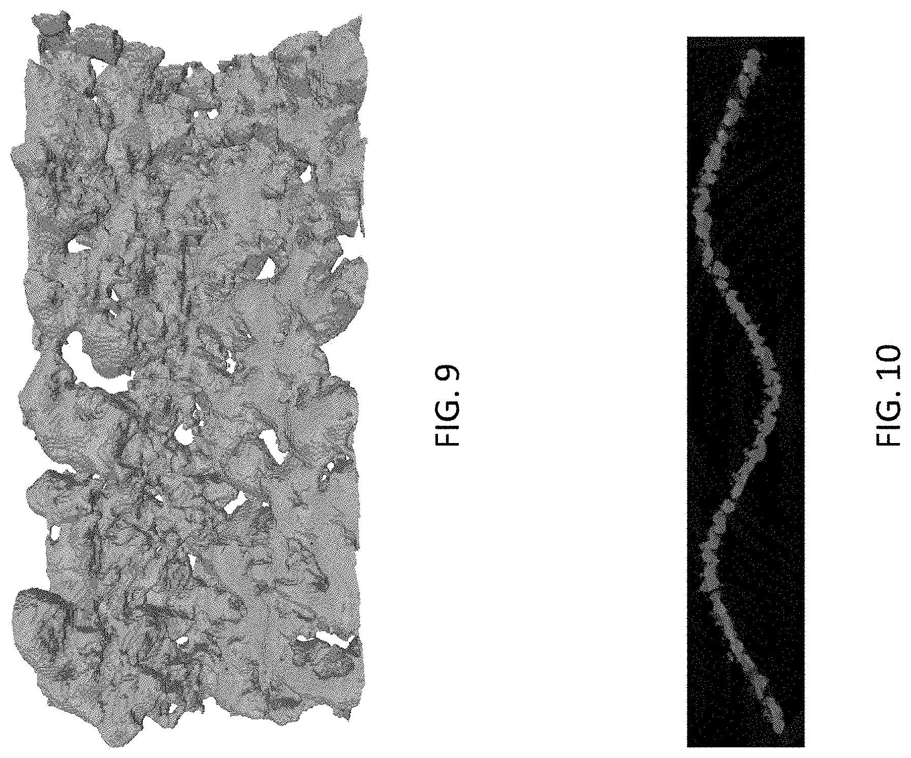
[0020] FIG. 9 is an image showing a front view of a .mu.CT-based 3D reconstruction of a nominally 400 .mu.m thick permeable membrane, and FIG. 10 is an image showing an image slice through a fin of the 3D reconstruction of FIG. 9.
[0021] FIGS. 11 and 12 are contour plots comparing, respectively, the ratio of the pressure drop, .DELTA.P.sub.PMM/.DELTA.P.sub.MMC, and the thermal resistance, .DELTA.R.sub.th,PMM/.DELTA.R.sub.th,MMC, of the permeable membrane microchannel heat sink of FIG. 5 and the manifold microchannel heat sink of FIG. 3 at a fixed pumping power of 0.018 W.
[0022] FIGS. 13, 15, and 17 schematically represent perspective fragmentary views of, respectively, a manifold microchannel heat sink, a first permeable membrane microchannel heat sink in accordance with a nonlimiting embodiment of the invention, and a second permeable membrane microchannel heat sink in accordance with a nonlimiting embodiment of the invention, and FIGS. 14, 16, and 18 are images of specimens of the heat sinks of, respectively, FIGS. 13, 15, and 17 fabricated in aluminum alloy AlSi.sub.10Mg via direct metal laser sintering (DMLS).
[0023] FIG. 19 is a graph plotting a comparison of measured pressure drop as a function of flow rate for the manifold microchannel heat sink of FIG. 14 and the permeable membrane microchannel heat sink of FIG. 18 (+0.172 kPa error bars are not shown).
[0024] FIG. 20 is a graph plotting a comparison of the performance of the manifold microchannel heat sink of FIG. 14 and permeable membrane microchannel heat sink of FIG. 18 while subjected to different pumping powers that allowed for a comparison of the heat sinks at approximately equal pressure drops.
DETAILED DESCRIPTION OF THE INVENTION
[0025] The following describes the development, fabrication, and evaluation of heat sinks that incorporate complex non-linear three-dimensional (3D) structures comprising one or more porous walls (membranes) as their primary heat transfer surface(s), whereby the heat sinks contain internal porosity that creates fluid flow paths through the membranes to increase the area available for heat transfer, and the membranes are sufficiently thin to reduce pressure drop in comparison to a manifold microchannel heat sink. The internal porosity-containing heat sinks, referred to herein as permeable membrane microchannel (PMM) heat sinks, were fabricated using direct metal laser sintering (DMLS) of an aluminum alloy (AlSi.sub.10Mg), though it should be understood that heat sinks formed by other fabrication techniques and materials are also within the scope of the present invention.
[0026] Investigations discussed below benchmarked PMM heat sinks against a manifold microchannel (MMC) heat sink both experimentally and by using a reduced-order model to explore the relative performance trends between these designs. The investigations evidenced that the inclusion of a porous membrane in the PMM heat sinks as the primary heat transfer surface(s) enabled the heat sinks to meet the same heat transfer capability as the MMC heat sink, but with a reduced total volume as compared to the MMC heat sink by eliminating the need for a separate manifold layer to route fluid to their heat transfer surfaces. Both the porosity of the membranes and their complex shapes serve to increase the surface area available for fluid flow and heat transfer, allowing for potential benefits in both hydraulic and thermal performance.
[0027] Nomenclature Used in the Following Discussion: [0028] A Area [0029] C Coefficient in Eq. (2) [0030] D.sub.H Hydraulic diameter [0031] D.sub.p Particle diameter [0032] f.sub.F Fanning friction factor [0033] G Mass flux [0034] h Heat transfer coefficient [0035] K.sub..infin. Incremental pressure drop number [0036] k Thermal conductivity [0037] L Length [0038] Nu Nusselt number, hD/k.sub.1 [0039] Pr Prandtl number, c.sub.p.mu./k.sub.1 [0040] .DELTA.P Pressure drop [0041] Q.sub.in Power input [0042] R Thermal resistance [0043] Re Reynolds number, GD/.mu. [0044] T Temperature [0045] t.sub.wall Wall/membrane thickness [0046] u.sub.sup Superficial velocity [0047] x.sup.+ Dimensionless entry length
[0048] Greek Symbols Used in the Following Discussion: [0049] .kappa. Permeability [0050] .alpha. Aspect ratio [0051] .mu. Dynamic viscosity [0052] .rho. Density [0053] .phi. Porosity
[0054] Subscripts Used in the Following Discussion: [0055] app Apparent, accounting for developing flow [0056] base Evaluated at the heat sink base [0057] ch Channel [0058] dev Developing flow [0059] eff Effective [0060] l Evaluated for the fluid [0061] m Evaluated at mean fluid temperature [0062] s Evaluated for the solid material [0063] sf Solid-fluid interface [0064] tot Total [0065] w Evaluated at interfacial temperature
[0066] As the hydraulic diameter of a channel decreases, there is a proportional increase in internal convective heat transfer coefficient between a fluid flowing through the channel and the walls of the channel. This scaling is the fundamental premise for using microscale channels (microchannels) in heat sinks. Microchannel geometries can be directly fabricated, or alternatively, this effect can be achieved using an open-celled microporous media in which the effective hydraulic diameter reduces to the pore size. As a heat transfer surface, porous media can generally achieve smaller hydraulic diameters and higher internal surface area-to-volume ratios than directly fabricated straight microchannels, though at the cost of a significantly higher pressure drop. To minimize this pressure drop penalty, investigations leading to the present invention developed, fabricated, and evaluated porous membranes whose wall thicknesses were minimized to reduce the flow length through their narrow pore paths, and whose frontal areas were augmented to reduce the flow rate through any one pore path.
[0067] As previously discussed, a common design goal of heat sinks is to reduce the pressure drop, which is particularly a challenge for microchannel heat sinks that leverage very small channels for heat exchange. As noted in reference to FIG. 2, manifold microchannel heat sinks use a manifold layer to reduce the effective flow length through their microchannels. Because manifold microchannel heat sinks are well accepted as exhibiting low pressure drops, a manifold microchannel heat sink design was utilized as a benchmark for the investigations leading to the present invention.
[0068] FIGS. 3 and 4 represent, respectively, a fragmentary perspective view and a top-down unit cell schematic view of a manifold microchannel (MMC) heat sink 10 having the selected design. The heat sink 10 comprised a heat transfer layer 12 of straight microchannels 14 beneath a separate manifold layer 16 with inlet and outlet channels 18A and 18B that are larger than the microchannels 14 and distribute the flow across the entire bank of microchannels 14. For the purpose of dissipating heat from a source (not shown), for example, an electronic device, the heat transfer layer 12 is placed in thermal contact with the source and a working fluid flows through the heat sink 10 by traveling along the manifold inlet channel 18A in the manifold layer 16, down into the microchannel layer 12 within the heat transfer layer 12, across a short flow length in the microchannels 14, and then exits via the smaller outlet channel 18B in the manifold layer 16.
[0069] FIGS. 5 and 6 represent, respectively, a fragmentary perspective view and a top-down unit cell schematic view of a nonlimiting embodiment of a permeable membrane microchannel (PMM) heat sink 20 within the scope of the invention. The PMM heat sink 20 comprises microchannels 22 defined and separated by a bank of thin porous and permeable walls or "membranes" 24 that define the primary heat exchange surfaces of the heat sink 20, which includes the walls of pores (not shown) within the membranes 24. As such, the permeable membranes 24 are deemed to be permeable if permeable to a working fluid used to absorb and conduct thermal energy from the heat sink 20. The microchannels 22 and membranes 24 are represented as disposed in a single tier or layer on a base 26 of the heat sink 20, with the membranes 24 being contiguous with and projecting away from the base 26.
[0070] For the purpose of dissipating heat from a source (not shown), for example, an electronic device, the base 26 of the heat sink 20 is placed in thermal contact with the source and the working fluid flows through the heat sink 20 to absorb and transfer heat from the source by conductive heat transfer from the source to the membranes 24 and then convective heat transfer from the membranes 24 to the working fluid. The fluid enters the heat sink 20 through inlets 28 associated with some but not all (alternating in FIGS. 5 and 6) of the microchannels 22, designated as inlet microchannels 22A. Though a single inlet microchannel 22A is shown associated with each inlet 28, in some embodiments multiple inlet microchannels 22A may be fluidically connected to each inlet 28. Solid endcaps 30 prevent a direct exit of the fluid from the heat sink 20 through the inlet microchannels 22A, and instead all of the fluid flowing through the heat sink 20 must pass from each inlet microchannel 22A to one of the remaining microchannels 22, designated as the outlet microchannels 22B, through the thin permeable membranes 24 that separates the microchannels 22A and 22B before the fluid exits the heat sink 20 through outlets 32 associated with the outlet microchannels 22B. Though a single outlet microchannel 22B is shown associated with each outlet 32, in some embodiments multiple outlet microchannels 22B may be fluidically connected to each outlet 32.
[0071] As the primary heat exchange surfaces of the heat sink 20, the permeable membranes 24 act as fins that conduct heat from the base 26 and transfer the absorbed heat to the fluid passing through the pores within the membranes 24. The membranes 24 have nonlinear horizontal profiles (approximating a sine wave) and nonlinear vertical profiles (not perpendicular to the base 26), which have the effect of increasing the surface area of the face of each membrane 24 (i.e., the surfaces of each membrane 24 exposed to one of the microchannels 22) as compared to a flat membrane sheet, so as to reduce the pressure drop and increase the heat exchange area. Though the membranes 24 are nonlinear, they effectively define flowpaths through the microchannels 22 that may be generally described as parallel, as evident from FIGS. 5 and 6. The specific profiles of the membranes 24 that were evaluated were heuristically chosen for the investigations. However, the shapes of the membranes 24 offer a design variable that is only limited by the capabilities of the process used to fabricate PMM heat sinks within the scope of the invention.
[0072] Because subtractive and other conventional machining processes are not able to readily produce the complex geometry with permeable membranes 24 shown in FIG. 5, additive manufacturing techniques were used to fabricate PMM heat sinks that were evaluated. For production of microchannel heat sinks, accurate fabrication of sub-millimeter features in a high-thermal-conductivity metal was desired. Direct metal laser sintering (DMLS) is a commercially mature, widely available technology that is suitable for producing microchannel heat sinks with features on the order of hundreds of micrometers. DMLS is a powder bed fusion technology that uses a laser to selectively fuse a thin layer of metal powder to create a cross-section of the desired component. After fusion, another thin layer of powder is deposited on top of the fused layer, and the process is repeated until the desired component is completed. In this way, the component is built up layer by layer. Based on previous work and the literature, a microchannel width of about 500 .mu.m is near the lower limit of what can be commercially fabricated by DMLS because, though laser spot sizes of 50-100 .mu.m are common, there is a significant heat-affected zone. Therefore, the membrane pores in the PMM heat sinks were not directly printed, but rather the material was rendered porous during the powder fusion process to achieve these small features. As previously noted, the PMM heat sinks were fabricated from AlSi.sub.10Mg, an aluminum alloy with a nominal thermal conductivity k.sub.s of about 110 W/m-K, though a number of alloys are available for use with DMLS.
[0073] To evaluate the relative performance of nonlimiting embodiments of PMM heat sinks of this invention to the MMC heat sink 10 represented in FIGS. 3 and 4, a reduced-order model was developed. The model was used to study performance trends of PMM heat sinks as a function of the membrane characteristics and provide an assessment of PMM heat sink designs relative to the MMC heat sink 10.
[0074] The pressure drops across the heat sinks were assumed to occur primarily across the smallest hydraulic diameter features used for heat exchange (viz., the microchannels 14 in the MMC heat sink 10 and the porous membrane 24 in the PMM heat sink 20) and the outlet channels of the heat sinks. The pressure drops at the inlets of each heat sink were presumed to be lower than in the outlets due to pressure recovery by fluid discharge from the inlets and, in the MMC heat sink 10, the smaller hydraulic diameter of the outlets. For the outlet channel pressure drop in both the MMC and PMM heat sinks, a conservative estimate was to assume that all of the flow must travel along the entire outlet channel length:
.DELTA. P ch = 2 f F , app L ch G ch 2 .rho. l D H ( 1 ) ##EQU00001##
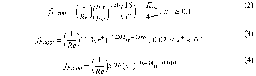
[0075] where f.sub.F,app is the apparent Fanning friction factor from Ref. T. M. Harms, M. J. Kazmierczak, and F. M. Gerner, "Developing convective heat transfer in deep rectangular microchannels," Int. J. Heat Fluid Flow, vol. 20, no. 2, pp. 149-157 (April 1999), which accounts for developing flow effects and is given by
f F , app = ( 1 Re ) ( .mu. w .mu. m ) 0.58 ( 16 C ) + K .infin. 4 x + , x + .gtoreq. 0.1 ( 2 ) f F , app = ( 1 Re ) 11.3 ( x + ) - 0.202 .alpha. - 0.094 , 0.02 .ltoreq. x + < 0.1 ( 3 ) f F , app = ( 1 Re ) 5.26 ( x + ) - 0.434 .alpha. - 0.010 ( 4 ) ##EQU00002##
where:
x + = L ch D H Re ##EQU00003##
is the dimensionless entry length,
C = 2 3 + ( 11 24 ) .alpha. ( 2 - .alpha. ) ##EQU00004##
is a correction factor for friction factors in rectangular channels, and K.sub..infin.=-0.906.alpha..sup.2+1.693.alpha.+0.649 is the incremental pressure drop number that accounts for the developing region.
[0076] The pressure drop in the microchannels 14 for the MMC heat sink 10 can be calculated using Equation (1) using the fractional flow rate that goes through any one microchannel 14 and the effective flow length between the inlet and outlet. It is important to account for the developing flow effects in the heat transfer layer 12 containing the microchannels 14, even for reduced-order fidelity, as the entire flow length can be developing.
[0077] The pressure drop across the membrane in a PMM heat sink can be calculated using Darcy's Law
.DELTA. P wall = u sup .mu. l t wall .kappa. ( 5 ) ##EQU00005##
[0078] whu.sub.sup={dot over (V)}/A ere is the superficial velocity within the porous medium.
[0079] The permeability K of the membrane was estimated using the Carman-Kozeny equation
K = D p 2 .phi. 3 150 ( 1 - .phi. ) 2 ( 6 ) ##EQU00006##
[0080] It was assumed that all heat transfer to the fluid occurs within the heat transfer layer 12 in the MMC heat sink 10 and with the membranes in the PMM heat sinks. For the microchannels, the Nusselt number was calculated assuming hydrodynamically and thermally developing flow as
Nu dev = 1.86 ( RePrD H L ) 1 3 ( .mu. l .mu. wall ) 0.14 ( 7 ) ##EQU00007##
[0081] The heat transfer surface areas of the microchannels 12 and 22 were trivially calculated from the given channel geometry. For the membrane 24, the Nusselt number was obtained from a particle-diameter-dependent correlation developed in K. K. Bodla, J. Y. Murthy, and S. V. Garimella, "Direct Simulation of Thermal Transport Through Sintered Wick Microstructures," J. Heat Transf., vol. 134, no. 1, p. 012602 (2012), as
Nu sf = h sf D p k l = 2.081 + 0.296 ( Re D p 0.6 Pr 1 3 ) 1.2 ( 8 ) ##EQU00008##
[0082] where the particle diameter was taken as the powder
? = 1 ? ? indicates text missing or illegible when filed ##EQU00009##
clump size in the fabricated membrane 24. The internal solid-fluid interfacial area of the membrane 24 was estimated as
A sf = 6 ( 1 - .phi. ) V tot D p ( 9 ) ##EQU00010##
[0083] The fin efficiency of the microchannel membranes 24 can be calculated using the nominal thermal conductivity of the solid printed aluminum. For the porous membranes 24, the effective thermal conductivity, k.sub.eff, was calculated in accordance with the effective medium theory model, and is given as
k eff = 1 4 ( ( 3 .phi. - 1 ) k s + ( 3 ( 1 - .phi. ) - 1 ) k l + ( ( 3 .phi. - 1 ) k s + ( 3 ( 1 - .phi. ) - 1 ) k l ) 2 + 8 k l k s ) ( 10 ) ##EQU00011##
[0084] To compare nonlimiting embodiments of PMM heat sinks of this invention to the MMC heat sink 10 represented in FIGS. 3 and 4, the total pressure drop was calculated from the sum of the two component drops for each.
[0085] The convective thermal resistance was calculated as using the heat transfer coefficient and the nominal heat transfer surface area for each.
[0086] A flow loop identical to that described in I. L. Collins, J. A. Weibel, L. Pan, and S. V. Garimella, "Evaluation of Additively Manufactured Microchannel Heat Sinks," IEEE Trans. Compon. Packag. Manuf. Technol. (2018), was used to experimentally characterize the thermal and hydraulic performance of the heat sinks. The flow loop used deionized water as the working fluid and imposed controlled, constant boundary conditions to the heat sinks and enabled measurement of the flow rate, fluid temperature, heat sink temperature, pressure drop, and power input. The key components are briefly summarized here.
[0087] The system was closed and a gear pump was used to circulate the working fluid. The flow rate was measured and the fluid filtered and preheated before entering a test section that held the heat sink. A 200 W ceramic heater provided adjustable heat input to the heat sink being tested. After exiting the heat sink, the fluid was cooled back to ambient temperature and returned to a flexible reservoir that maintained ambient pressure.
[0088] The test section, which secured the heat sink and heater together, positioned thermocouples for temperature measurements and contained pressure taps to measure the pressure drop, was modified slightly compared to I. L. Collins, J. A. Weibel, L. Pan, and S. V. Garimella, "Evaluation of Additively Manufactured Microchannel Heat Sinks," IEEE Trans. Compon. Packag. Manuf. Technol. (2018). Due to the lack of an incorporated lid on the heat sinks due to fabrication constraints and a desire to visualize the heat transfer features, a silicone rubber gasket was used to seal the interface between the heat sink and the component routing the flow into the part. The inlet temperature of the working fluid was maintained at 30.degree. C.
[0089] Prior to testing, the heat sinks were cleaned with compressed air and inserted in the test section. The experimental heat loss was measured by assembling the test section and applying power without the presence of the working fluid. After reaching a steady temperature at each power, the base heat sink temperature was recorded. A best-fit line, assuming a zero intercept, was fitted to these measurements to yield an empirical correlation and allow for conservative estimation of the temperature-dependent heat loss based on the base temperature of the heat sink. The range of heat loss in this study was 2.8% to 4.1%.
[0090] To characterize the hydraulic performance of the heat sinks, the flow rate through the unheated test section was varied over the range from about 50 mL/min to about 500 mL/min in 50 mL/min increments. After achieving steady conditions at each flow rate, the pressure drop across the heat sink was measured. The measured pressure drop was then used to identify the flow rates needed to achieve a comparison of the thermal performance between the two heat sink sinks at a constant pumping power. Two nominal pumping powers of 0.008 W and 0.018 W were chosen for the thermal performance characterization.
[0091] At each of the pumping powers, the heat input power to the heat sink was incremented from 0 W to 200 W in steps of 20 W. At each step, the system was allowed to reach steady state and then data were recorded for 60 s. A single time-averaged value was reported for each measurement. The thermal performance was characterized by the total thermal resistance of the heat sinks
R tot = T base - ? Q in ? indicates text missing or illegible when filed ( 11 ) ##EQU00012##
which can be calculated directly from the measured temperatures at the center of the heat sink base and the fluid inlet temperature, as well as the loss-adjusted heat input.
[0092] For a given heat sink geometry and flow rate, the thermal resistance was expected to be constant with power input during single-phase operation; changes in heat flux translated to proportional changes in the streamwise temperature gradient within the fluid and the local temperature difference between the convection surface and the bulk fluid. Due to the near-constant values of thermal resistance measured across the range of power inputs, the thermal resistance was reported as an arithmetic mean of all test points from 0 W to 200 W for a given heat sink and flow rate.
[0093] The sensor uncertainties specified by the manufacturers are listed in Table 1 below.
TABLE-US-00001 TABLE 1 Uncertainty in measured and calculated values. Measured Value Uncertainty Pressure drop .+-.0.172 kPa Volumetric flow rate .+-.5 mL/min Temperature .+-.1.0.degree. C. Voltage .+-.<1% Calculated Value Mean Uncertainty (Range) R.sub.tot 3.1% (1.1-12.9%)
[0094] The uncertainty in calculated thermal resistance is also listed, and was determined using a sequential perturbation method. The uncertainty in thermal resistance was highest at lower flow rates due to the smaller temperature difference between the heat sink base and the working fluid.
[0095] An MMC heat sink configured as shown in FIGS. 3 and 4 was used as the benchmark for comparison against nonlimiting embodiments of PMM heat sinks of this invention. The MMC heat sink was held fixed, using the minimum possible feature sizes based on the fabrication limits for the geometry. The manifold layer (16 in FIGS. 3 and 4) was 1.5 mm tall and had 1.0 mm-thick solid wall features, with inlet and outlet channel widths of 1.5 and 0.5 mm, respectively. These channel widths were in accordance with several design optimizations performed in the literature that have indicated the ideal single-phase inlet-to-outlet width ratio is 3:1. The effective flow length, from inlet to outlet through the microchannels (14 in FIGS. 3 and 4), was thus 2.00 mm. The total footprint of the heat transfer layer (12 in FIGS. 3 and 4) was 15.0 mm.times.15.5 mm and was covered by sixteen rectangular microchannels of 0.5 mm width and 2.0 mm height, spaced by 0.5 mm-wide solid walls (fins). The base thickness between the bottom of the heat sink and the bottom of its heat transfer layer was 1.0 mm Though thinner widths are possible based on the fabrication limits, this thickness was chosen to eliminate any potential for leakage. A 250 .mu.m deep, 1000 .mu.m wide groove ran from one edge of the heat sink to the center, allowing for placement of a thermocouple to measure the base temperature.
[0096] A PMM heat sink configured as shown in FIGS. 5 and 6 was fabricated to have membranes (24 in FIGS. 5 and 6) that were 2.0 mm tall and covered a 15.0 mm.times.15.5 mm footprint, identical to the heat transfer layer envelope in the MMC heat sink (note that the PMM heat sink was more compact compared to the MMC heat sink if considering the manifold layer of the latter). The membranes (fins) were nominally 400 .mu.m thick, the thinnest width successfully fabricated at the process parameter set used for the PMM heat sink. The permeable membranes had a curved profile in the horizontal plane, with an amplitude of 0.5 mm and a wavelength of 25% of the channel length. The vertical profile (normal to the heat sink base 26 in FIGS. 5 and 6) was that of a triangular chevron with an amplitude equal to the width of the membrane. The inlet and outlet channels (28 and 32 in FIGS. 5 and 6) had widths of 0.6 mm. The solid endcaps (30 in FIGS. 5 and 6) at the ends of the microchannels (22A in FIGS. 5 and 6) were 0.5 mm thick. The base thickness was identical to the manifold design and also contained a thermocouple groove.
[0097] In the PMM heat sink, the membrane pore characteristics and thickness that can be successfully fabricated with the additive process are unknown. The following describes an evaluation of the range of membrane characteristics that can be fabricated via additive manufacturing, inputs a range of membrane characteristics into the reduced-order model to identify the design space in which the PMM heat sink is predicted to perform well, and describes the experimental evaluation of a PMM heat sink design that was predicted to provide improved performance compared to the MMC heat sink.
[0098] Direct metal laser sintering fabrication processing parameter sets for achieving induced porosity in AlSi.sub.10Mg are not commonly available. A set of process-tuning sample cubes was designed and fabricated to determine the membrane thickness that could be achieved at different bulk sample porosities. To this end, ten samples were fabricated in collaboration with a commercial vendor (EOS M280; GPI Prototype & Manufacturing Services), each with different laser and scanning parameters. The geometry of the sample cubes and a photograph of one fabricated part are shown in FIGS. 7 and 8. The sample cube had a solid base layer, a porous core layer in the center, and a solid top layer. The porous core layer was used to assess the nominal bulk porosity that was achieved at the given processing parameters. A series of six membranes (fins) of differing widths between 150 and 500 .mu.m were built on the solid top surface. These fins have the same chevron profile as the heat sink, while the height of the fins was 1.0 mm and the wavelength was 5.0 mm. Across the set of ten samples cubes, porosities between 12-23% were achieved, as determined based on mass and volume measurements. The thinnest fins below 300 .mu.m in width failed to build on all samples. The 300 .mu.m-wide fins were successfully built when the bulk porosity was low (<-18%) and the 400 .mu.m and 500 .mu.m fins were successfully constructed on all samples (as can be seen for the 23% porosity sample in FIG. 8.
[0099] In addition to optical inspection, .mu.CT scanning (Bruker Scyscan 1272) was used to non-destructively examine the morphology of the permeable membranes. FIG. 9 shows a 3D reconstruction of a 3 mm-long section of the nominally 400 .mu.m thick membrane from the sample cube shown in FIG. 8. From the reconstruction, it was found that the effective thickness of the membrane was below that of the nominal geometry specified during printing, approximately 300 .mu.m. This was due to the fact that, when fabricating porous features, the standard laser-scanning dimensional offsets that compensate for the heat-affected zone and melt pool size during printing of solid features were not accurate (such offsets were disabled entirely during printing of these porous parts). Additionally, while the powder used to fabricate the samples has a mean particle diameter of 45 .mu.m, the membrane exhibited larger clumps of solid material and pores. The solid clump sizes were approximately 250 .mu.m in diameter (the membrane was only 1-2 clump diameters thick), with membrane pores ranging between 150-400 .mu.m in diameter. These measured clump sizes and pore diameters were used as inputs to the reduced-order model to evaluate the viability of the permeable membrane microchannel design compared to the benchmark manifold microchannel design, for a range of membrane porosities and thicknesses.
[0100] The performance of the PMM heat sink was evaluated relative to the MMC heat sink 10 based on the pressure drop ratio, .DELTA.P.sub.PMM/.DELTA.P.sub.MMC, and the convective thermal resistance ratio, .DELTA.R.sub.th,PMM/.DELTA.R.sub.th,MMC. The performance ratios were compared at a constant pumping power of 0.018 W. While various performance factors could be used to assess the heat sinks, comparison of the thermal resistance at a constant pumping power is common. However, for a fair comparison it is important to ensure that the two heat sinks also had the same order of pressure drop at this pumping power, such that they would use similar pumping technologies.
[0101] FIGS. 11 and 12 plot contours of the pressure drop ratio (FIG. 11) and thermal resistance ratio (FIG. 12) for ranges of membrane thickness and porosity that encompass and expand upon those achieved in the fabrication of the samples cubes. FIG. 11 shows that the pressure drop over a majority of the viable parameter range studied was within a half-order of magnitude, and that the pressure ratio improved (i.e., is reduced) as the membrane becomes thinner and more porous. Conversely, FIG. 12 shows that as the membrane becomes thicker and less porous, the relative thermal resistance of the PMM heat sink improved. Thicker and less porous membranes increase the interfacial area and the fin efficiency, leading to low thermal resistance at the cost of a higher pressure drop. For a membrane with an effective thickness of 300 .mu.m and a porosity of 23% (within the range demonstrated for the fabricated sample cubes of FIG. 8), the model predicted a 35% reduction in the pressure drop and a 28% reduction in the convective thermal resistance for the PMM heat sink compared to the MMC heat sink. This membrane width and porosity were used to fabricate and experimentally characterize a PMM heat sink as discussed below.
[0102] MMC and PMM heat sinks were commercially fabricated using the same aluminum alloy (AlSi.sub.10Mg) and AM process (DMLS) as discussed above. The fabricated heat sinks are schematically represented in FIGS. 13 and 17, and images of the fabricated heat sinks are shown in FIGS. 14 and 18. The MMC heat sink of FIG. 14 was fabricated to have microchannels that were 500 .mu.m wide and 2000 .mu.m deep, whereas the PMM heat sink of FIG. 18 was fabricated to have membranes that were 400 .mu.m thick, microchannels that were 600 .mu.m wide, and two inlets per inlet microchannel. An additional PMM heat sink that was prepared but not evaluated during this phase of the investigation is schematically represented in FIG. 15 and shown in FIG. 16. The PMM heat sink of FIGS. 15 and 16 corresponds to the PMM heat sink 20 of FIGS. 5 and 6, characterized by permeable membranes that were 400 .mu.m thick, microchannels that were 1200 .mu.m wide, and a single inlet per inlet microchannel.
[0103] The measured pressure drops of the heat sinks of FIGS. 14 and 18 are shown in FIG. 19 as a function of total flow rate. As predicted by the reduced-order model, the pressure drop of the PMM heat sink (FIG. 14) was lower than the MMC heat sink (FIG. 18). The pressure drop reduction was between 20-70%, with higher reductions being achieved at higher flow rates. The magnitude of the pressure drop was very low for both heat sinks, on the order of less than 4 kPa at 500 mL/min as compared to more typical pressure drop ranges of from tens to hundreds of kPa.
[0104] The pressure drop data from the adiabatic hydraulic testing are shown (open symbols) as a function of pumping power in FIG. 20 for both heat sinks. The pressure drop data measured during the thermal testing are superimposed as filled symbols. The thermal test points were chosen to enable comparison of the MMC and PMM thermal resistances at both constant pumping power (about 0.008 W and about 0.018 W) and pressure drop (about 2.5 kPa). The measured values of thermal resistance are annotated in FIG. 20 next to the corresponding pressure drop data point. At a pumping power of 0.008 W, the thermal resistance of the PMM heat sink (FIG. 18) was 10% lower than the MMC heat sink (FIG. 14) and the pressure drop was lower by 26%. At the higher nominal pumping power of 0.018 W, the reduction in thermal resistance was 17% and the reduction in pressure drop was 28%. At a constant pressure drop of 2.5 kPa, the thermal resistance of the PMM heat sink was lower by 25% compared to the MMC heat sink. From these data, it was shown that the same thermal resistance can be achieved with the PMM heat sink at a 56% lower pressure drop. The PMM heat sink was unequivocally demonstrated to provide improved performance over the MMC heat sink benchmark.
[0105] The reduced-order model predictions and the experimental results compared favorably at the higher nominal pumping power of 0.018 W. The model predicted a pressure drop reduction of 35% and a decrease in convective thermal resistance of 28%. The experimental data indicated decreases of 28% in the pressure drop and 17% in the total thermal resistance. The difference in the thermal resistances can be attributed to the additional thermal resistances due to conduction through the solid base and the caloric temperature rise in the fluid, which were fixed between the PMM and MMC heat sinks.
[0106] In conclusion, the investigations discussed above demonstrated the performances of certain PMM heat sink designs that were experimentally characterized and benchmarked against a high-performance MMC heat sink design. A reduced-order model was used to assess the relative pressure drop and thermal resistance between the PMM and MMC heat sinks at a constant pumping power for a range of membrane thicknesses and porosities. Experimental characterizations of the heat sink designs showed that PMM heat sink designs can offer a reduced thermal resistance at a constant pressure drop or pumping power. The PMM heat sink designs also demonstrated the ability of additive manufacturing to produce complex geometries incorporating locally porous features, otherwise unobtainable via conventional manufacture, to achieve heat sink performance enhancement.
[0107] While the invention has been described in terms of particular embodiments and investigations, it should be apparent that alternatives could be adopted by one skilled in the art. For example, a PMM heat sink could differ in appearance and construction from the embodiments described herein and shown in the drawings, functions of certain components of the PMM heat sinks could be performed by components of different construction but capable of a similar (though not necessarily equivalent) function, and various materials could be substituted for those noted. As such, it should be understood that the above detailed description is intended to describe the particular embodiments represented in the drawings and certain but not necessarily all features and aspects thereof, and to identify certain but not necessarily all alternatives to the represented embodiments and described features and aspects. As a nonlimiting example, the invention encompasses additional or alternative embodiments in which one or more features or aspects of a particular embodiment could be eliminated or two or more features or aspects of different embodiments could be combined. Accordingly, it should be understood that the invention is not necessarily limited to any embodiment described herein or illustrated in the drawings, and the phraseology and terminology employed above are for the purpose of describing the illustrated embodiments and investigations and do not necessarily serve as limitations to the scope of the invention. Therefore, the scope of the invention is to be limited only by the following claims.
* * * * *
D00000
D00001
D00002
D00003
D00004
D00005
D00006
D00007
D00008
D00009


XML
uspto.report is an independent third-party trademark research tool that is not affiliated, endorsed, or sponsored by the United States Patent and Trademark Office (USPTO) or any other governmental organization. The information provided by uspto.report is based on publicly available data at the time of writing and is intended for informational purposes only.
While we strive to provide accurate and up-to-date information, we do not guarantee the accuracy, completeness, reliability, or suitability of the information displayed on this site. The use of this site is at your own risk. Any reliance you place on such information is therefore strictly at your own risk.
All official trademark data, including owner information, should be verified by visiting the official USPTO website at www.uspto.gov. This site is not intended to replace professional legal advice and should not be used as a substitute for consulting with a legal professional who is knowledgeable about trademark law.