Drilling Unit Comprising an Electric Heave-Compensation System
BERGE MELING; Karsen ; et al.
U.S. patent application number 16/479185 was filed with the patent office on 2019-11-28 for drilling unit comprising an electric heave-compensation system. This patent application is currently assigned to National Oilwell Varco Norway AS. The applicant listed for this patent is National Oilwell Varco Norway AS. Invention is credited to Karsen BERGE MELING, Yngvar BOROY, Hans Anders ERIKSSON, Thor STRAND.
| Application Number | 20190360282 16/479185 |
| Document ID | / |
| Family ID | 58098469 |
| Filed Date | 2019-11-28 |


View All Diagrams
| United States Patent Application | 20190360282 |
| Kind Code | A1 |
| BERGE MELING; Karsen ; et al. | November 28, 2019 |
Drilling Unit Comprising an Electric Heave-Compensation System
Abstract
A drilling unit on a deck of a floating vessel, includes a drill tower structure with a heave-compensation system, a winch mounted at or near the deck, a crown block mounted at a top side of the drill tower structure and at least one wire rope between the winch and the crown block. The heave-compensation system includes a slideable support frame configured to be moved in a direction substantially parallel to the axial direction of the drill tower structure. Either the winch or the crown block is positioned within the slideable support frame such that a distance between the winch and the crown block is controlled by at least one electric motor or linear actuator. In an alternative embodiment in which a crown block in not employed, the winch is placed in the slideable support frame at the top side of the drill tower structure.
| Inventors: | BERGE MELING; Karsen; (Kristiansand S, NO) ; ERIKSSON; Hans Anders; (Fornebu, NO) ; BOROY; Yngvar; (Sogne, NO) ; STRAND; Thor; (Kristiansand, NO) | ||||||||||
| Applicant: |
|
||||||||||
|---|---|---|---|---|---|---|---|---|---|---|---|
| Assignee: | National Oilwell Varco Norway
AS Kristiansand S NO |
||||||||||
| Family ID: | 58098469 | ||||||||||
| Appl. No.: | 16/479185 | ||||||||||
| Filed: | February 15, 2018 | ||||||||||
| PCT Filed: | February 15, 2018 | ||||||||||
| PCT NO: | PCT/NO2018/050041 | ||||||||||
| 371 Date: | July 18, 2019 |
| Current U.S. Class: | 1/1 |
| Current CPC Class: | E21B 15/02 20130101; E21B 19/008 20130101; E21B 19/09 20130101; E21B 19/006 20130101 |
| International Class: | E21B 19/00 20060101 E21B019/00; E21B 15/02 20060101 E21B015/02; E21B 19/09 20060101 E21B019/09 |
Foreign Application Data
| Date | Code | Application Number |
|---|---|---|
| Feb 16, 2017 | EP | 17156406.5 |
Claims
1. Drilling unit for mounting on a deck of a floating vessel, the drilling unit comprising: a drill tower structure with a heave-compensation system for compensating vertical movements of the floating vessel due to waves, wherein the drilling unit further comprises: a winch, a crown block mounted at a top side of the drill tower structure and at least one wire rope provided between the winch and the crown block, wherein the heave-compensation system comprises a slideable support frame configured to be moved relative to the drill tower structure in a direction substantially parallel to the axial direction of the drill tower structure, and wherein either the winch or the crown block is provided within the slideable support frame such that a distance between the winch and the crown block is controllable, and wherein the position of the slideable support frame with respect to the drill tower structure is controlled by at least one electric motor or linear actuator.
2. The drilling unit according to claim 1, wherein the slideable support frame is provided with at least one friction track, and wherein the drill tower structure is provided with at least one rotatable friction wheel that is driven by the at least one electric motor or linear actuator, the at least one rotatable friction wheel being configured for rolling over the at least one friction track for controlling the position of the slideable support frame.
3. The drilling unit according to claim 1, wherein the drill tower structure is provided with at least one friction track, and wherein the slideable support frame is provided with at least one rotatable friction wheel that is driven by the at least one electric motor or linear actuator, the at least one rotatable friction wheel being configured for rolling over the at least one friction track for controlling the position of the slideable support frame.
4. The drilling unit according to claim 2, wherein the at least one friction wheel is directly driven by the at least one electric motor or linear actuator.
5. The drilling unit according to claim 2, comprising one or more respective gearing systems in between the at least one electric motor or linear actuator and the at least one friction wheel.
6. The drilling unit according to any one of claims 2, wherein the at least one friction track comprises a toothed rack.
7. The drilling unit according to any one of claims 2, wherein the at least one rotatable friction wheel comprises a pinion.
8. The drilling unit according to claim 1, wherein the winch is also configured for compensating vertical movements of the floating vessel due to waves.
9. The drilling unit according to claim 1, further comprising an energy recovery system connected to the at least one electric motor or linear actuator, wherein the energy recovery system is configured for storing energy generated by a load when the load is being lowered and for supplying it to the at least one electric motor or linear actuator when the load is being hoisted.
10. The drilling unit according to claim 1 wherein the winch is provided within the slideable support frame.
11. The drilling unit according to claim 1, wherein the crown block provided within the slideable support frame.
12. The drilling unit according to claim 1, wherein the winch located at a drill floor or deck (200).
13. The drilling unit according to claim 1, wherein the winch is located outside the drill tower structure (130).
14. The drilling unit according to claim 1, wherein the winch is located inside the drill tower structure (130).
15. The drilling unit according to claim 1, wherein the slideable support frame is configured for being lockable relative the drill tower structure.
16. Drilling unit for mounting on a deck of a floating vessel, the drilling unit comprising: a drill tower structure with a heave-compensation system for compensating vertical movements of the floating vessel due to waves, wherein the drilling unit further comprises a winch and at least one wire rope coupled to the winch, wherein the heave-compensation system comprises a slideable support frame provided at a top side of the drill tower structure, and wherein the slideable support frame is configured to be moved relative to the drill tower structure in a direction substantially parallel to the axial direction of the drill tower structure, and wherein the winch is provided within the slideable support frame, and wherein the position of the slideable support frame with respect to the drill tower structure is controlled by at least one electric motor or linear actuator.
Description
CROSS REFERENCE TO RELATED APPLICATIONS
[0001] This application is a 35 U.S.C. .sctn. 371 national state application of PCT/NO2018/050041 filed Feb. 15, 2018 and entitled "Drilling Unit Comprising an Electric Heave-Compensation System", which claims priority to European Patent Application No. 17156406.5 filed Feb. 16, 2017, each of which is incorporated herein by reference in their entirety for all purposes.
STATEMENT REGARDING FEDERALLY SPONSORED RESEARCH OR DEVELOPMENT
[0002] Not Applicable.
FIELD OF THE INVENTION
[0003] The present disclosure relates to a drilling unit for mounting on a deck of a floating vessel, the drilling unit comprising a drill tower structure with a heave-compensation system for compensating vertical movements of the floating vessel due to waves.
BACKGROUND
[0004] Floating drilling and intervention vessels must have a heave-compensation system to compensate for the vertical movements transferred from the wave surge to the vessel. Such a heave-compensation system can be mounted at the top side of the derrick or drill tower or anywhere in the load path if a stationary sheave is used.
[0005] Traditional heave-compensation systems are located at various places at the vessel to stabilize the vessel movements during operation. Reference is made to Frank Langlo's master thesis, entitled: "Application of reliability centered maintenance on a drilling system" from the Department of Mechanical and Structural engineering and Material Science, Faculty of Science and Technology, of the University of Stavanger, published June 2014. This publication is incorporated by reference herein and shows that known compensators typically are often characterized by a guided system mounted between a drilling tower (derrick) structure and a drilling machine, having the ability to store energy generated by the forces and speed from the waves. Traditional derrick compensator system may be placed at the top side of a derrick, using a hydraulic system for transferring the power. The energy storage is normally kept close to the actuators to minimize the loss, hence there will be a large amount of energy at the top side of the derrick, with a consistent risk, high cost and low serviceability.
SUMMARY OF THE DISCLOSURE
[0006] In view of the above, there is a need for a drilling unit having an improved heave-compensation system, which does not suffer from the drawbacks mentioned above, or at least to a much lesser extent.
[0007] The disclosure addresses at least one of the drawbacks of the prior art, or at least provide a useful alternative to prior art, and offers an improved and overall more compact design of a compensation system.
[0008] In a first aspect, the disclosure relates to a drilling unit for mounting on a deck of a floating vessel. The drilling unit comprises a drill tower structure with a heave-compensation system for compensating vertical movements of the floating vessel due to waves. The drilling unit further comprises a winch, a crown block mounted at a top side of the drill tower structure and at least one wire rope provided between the winch and the crown block. The heave-compensation system comprises a slideable support frame configured to be moved relative to the drill tower structure in a direction substantially parallel to the axial direction (in practise this is a vertical direction) of the drill tower structure, wherein either the winch or the crown block is provided within the slideable support frame such that a distance between the winch and the crown block is controllable. Furthermore, the position of the slideable support frame with respect to the drill tower structure is controlled by at least one electric motor or linear actuator.
[0009] The effects of the drilling unit in accordance with the disclosure are as follows. By providing a slideable support frame, which comprises either the crown block or the winch, the distance between the winch and the crown block may be made controllable. This opens up the way to compensate vertical movements of the floating vessel due to waves by simply moving the slideable support frame. The slideable support frame is actuated by at least one electric motor or linear actuator. That feature by itself is quite revolutionary as the prior art systems are all based on hydraulic systems. Switching the system towards the electrical domain leads to significant advantages. For instance, the heave-compensation system may now be fed by the same power supply as the winch system (which is often electrically driven). This renders the design of the whole drilling unit less complex. Furthermore, the heave-compensation system may, in certain embodiments, be combined with electrical energy recovery systems, i.e. the electrical energy recovery systems may be used to supply power to the heave-compensation system of the disclosure.
[0010] The winch itself may also heave-compensated, in that the actuation of the winch is done such that vertical movements of the floating vessel due to waves are compensated for. In such cases, the disclosure thus provides for an extra heave-compensation system, which either may support the other heave-compensation system or be used as a back-up system in case the other system fails. Both scenarios are very effective and advantageous for the oil industry.
[0011] In summary, the disclosure provides for accurate compensation, at reduced weight and volume and allows for energy storage in a safe and controlled area placed anywhere on the rig. Electric cabling of such heave-compensation system may be run to so-called VFD cabinets stored inside or below the deck. In this context, "safe" means non-hazardous/non-explosive. Serviceability may also be severely improved due to these factors and efficiency of electric systems are considerable better than traditional hydraulic systems.
[0012] In order to facilitate a fuller understanding of the disclosure, one or more expressions are further defined. Wherever in this description the wording "drill tower structure" is used, this must be interpreted as including hoisting towers, derricks and any other type of drilling structure. Wherever in this description the wording "crown block" is used, this must be interpreted as that part at the top side of the drill tower structure, which houses or holds at least one top sheave for guiding the at least one wire rope.
[0013] In an embodiment of the drilling unit in accordance with the disclosure, the slideable support frame is provided with at least one friction track, and the drill tower structure is provided with at least one rotatable friction wheel that is driven by the at least one electric motor or linear actuator. The at least one rotatable friction wheel is configured for rolling over the at least one friction track for controlling the position of the slideable support frame. This embodiment constitutes a first main variant of providing for a slideable support frame which position is controlled by an electric motor or linear actuator.
[0014] In an embodiment of the drilling unit in accordance with the disclosure, the drill tower structure is provided with at least one friction track, and the slideable support frame is provided with at least one rotatable friction wheel that is driven by the at least one electric motor or linear actuator. The at least one rotatable friction wheel is configured for rolling over the at least one friction track for controlling the position of the slideable support frame. This embodiment constitutes a second main variant of providing for a slideable support frame which position is controlled by an electric motor or linear actuator.
[0015] In an embodiment of the drilling unit in accordance with the disclosure, the at least one friction wheel is directly driven by the at least one electric motor or linear actuator. In this embodiment the electric motor or linear actuator may have a driving axle that is directly coupled to an axle of the friction wheel.
[0016] An embodiment of the drilling unit in accordance with the disclosure, further comprises one or more respective gearing systems in between the at least one electric motor or linear actuator and the at least one friction wheel. This embodiment is a variant of the previous-mentioned embodiment in that the electric motor or linear actuator now drives a gearing system, which on its turn drives the friction wheel.
[0017] In an embodiment of the drilling unit in accordance with the disclosure, the at least one friction track comprises a toothed rack. A toothed rack is able to provide a very large friction, particularly when a pinion (or wheel gear) is used to cooperate with it.
[0018] In an embodiment of the drilling unit in accordance with the disclosure, the at least one rotatable friction wheel comprises a pinion. A pinion is able to provide a very large friction, particularly when a toothed rack is used to cooperate with it.
[0019] In an embodiment of the drilling unit in accordance with the disclosure, the winch is also configured for compensating vertical movements of the floating vessel due to waves. As already mentioned, the disclosure may provide for a heave-compensation system that comes in addition to an already existing heave-compensation system (for example on the winch as is the case in this embodiment). Then the heave-compensation system of the disclosure may be used to either support the other heave-compensation system, or be used as a back-up in case that system fails.
[0020] An embodiment of the drilling unit in accordance with the disclosure, further comprises an energy recovery system connected to the at least one electric motor or linear actuator. The energy recovery system is configured for storing energy generated by a load when the load is being lowered and for supplying it to the at least one electric motor or linear actuator when the load is being hoisted. This embodiment makes the heave-compensation system of the disclosure more self-supporting, i.e. it does not or hardly requires power from a rig to be able to operate. More information on the implementation of an energy recovery system may be found in U.S. Pat. No. 7,923,946, for example, the disclosure of which is incorporated herein by this reference.
[0021] In the embodiments discussed hereinafter various variations with regards to the placement of the different parts of the disclosure are discussed.
[0022] In an embodiment of the drilling unit in accordance with the disclosure, the winch is provided within the slideable support frame. This embodiment concerns a first main group of embodiments of the disclosure.
[0023] In an embodiment of the drilling unit in accordance with the disclosure, the crown block is provided within the slideable support frame. This embodiment concerns a second main group of embodiment of the disclosure.
[0024] In an embodiment of the drilling unit in accordance with the disclosure, the winch is located at a drill floor or deck. In another embodiment, the winch is located outside the drill tower structure. In yet another embodiment, the winch is located inside the drill tower structure.
[0025] In an embodiment of the drilling unit in accordance with the disclosure, the slideable support frame is configured for being lockable relative the drill tower structure. This embodiment is advantageous in that the heave-compensation system of the disclosure can be effectively deactivated by the locking of the slideable support frame. Such feature may be convenient in case the hoisting activities of the drilling unit are not critical (i.e. not near the sea bottom) or when service is to be carried out on the drilling unit.
[0026] In a second aspect, the disclosure relates to a drilling unit for mounting on a deck of a floating vessel. The drilling unit comprises a drill tower structure with a heave-compensation system for compensating vertical movements of the floating vessel due to waves, wherein the drilling unit further comprises a winch and at least one wire rope coupled to the winch. The heave-compensation system comprises a slideable support frame provided at a top side of the drill tower structure, wherein the slideable support frame is configured to be moved relative to the drill tower structure in a direction substantially parallel to the axial direction of the drill tower structure, wherein the winch is provided within the slideable support frame, and wherein the position of the slideable support frame with respect to the drill tower structure is controlled by at least one electric motor or linear actuator.
[0027] The second aspect of the disclosure actually does not deviate much from the first aspect, and it includes similar embodiments as the further embodiments discussed with regards to the first aspect. The main difference is that the crown block is missing and that the winch actually takes over the role of the crown block. Thus, this embodiment concerns a third main group of embodiments of the disclosure.
[0028] In embodiments, there may be further sheaves added to the winch in order to guide the at least one wire rope. Even though all "intelligence" in these embodiments is located at the top side of the drill tower structure, still the same principle of the disclosure is used, namely that the heave-compensation is carried out by controlling the position of the slideable support frame using an electric motor or linear actuator in order to vary the distance, measured along the at least one wire rope, between the winch and the sea (as is indirectly also the case for the other two embodiments). Therefore, these embodiments concern the same disclosure as the embodiments of the first aspect.
BRIEF DESCRIPTION OF THE DRAWINGS
[0029] Exemplary embodiments of this disclosure are illustrated in the accompanying drawings, wherein:
[0030] FIG. 1 shows a perspective view of a first main embodiment of the drilling unit in accordance with the disclosure;
[0031] FIG. 2 shows a perspective view of a slightly modified version of the embodiment of FIG. 1;
[0032] FIG. 3 shows the embodiment of FIG. 2, seen from a different view point;
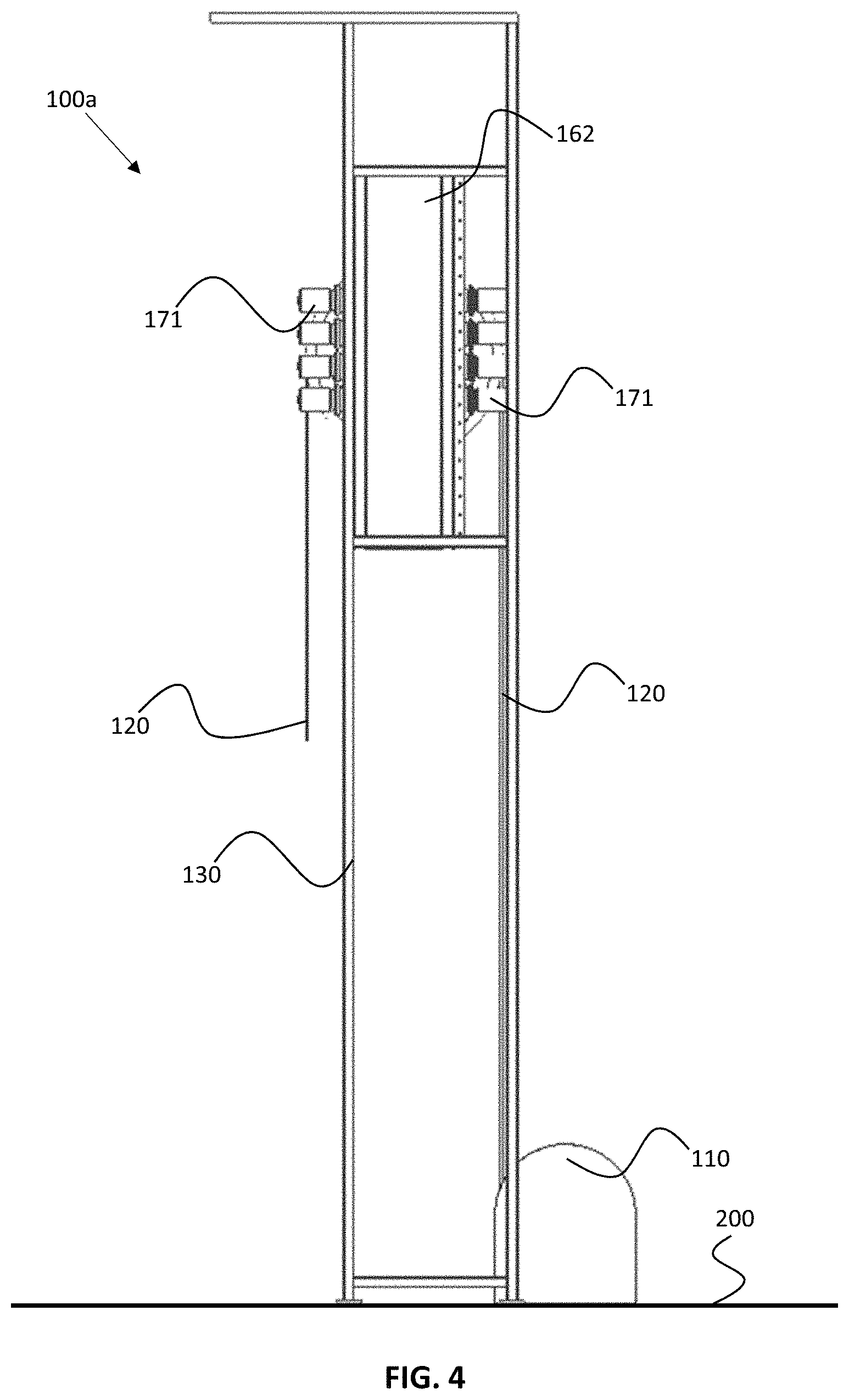
[0033] FIG. 4 shows a side view of the embodiment of FIG. 2;
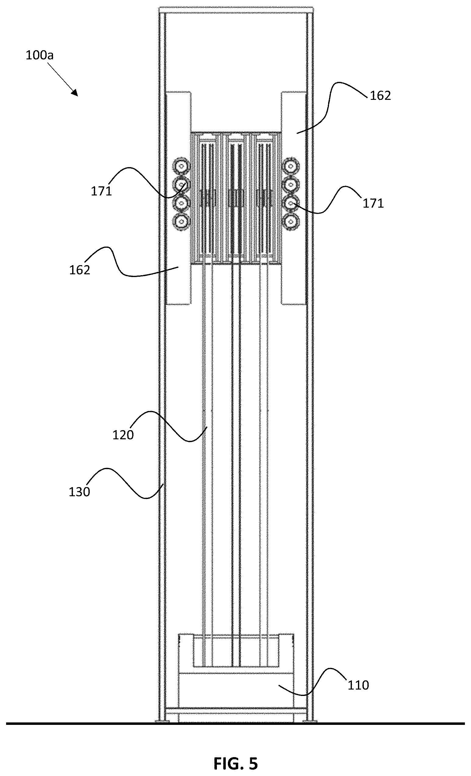
[0034] FIG. 5 shows a front view of the embodiment of FIG. 2;
[0035] FIG. 6 shows a top view of the embodiment of FIG. 2;
[0036] FIG. 7 shows a slideable support frame in accordance with the embodiment of FIG. 2;
[0037] FIG. 8 shows an enlarged view of part of FIG. 6 illustrated by AA;
[0038] FIG. 9 shows an enlarged view of the drives foundation and the drives assembly of the embodiment of FIG. 2;
[0039] FIG. 10 shows a perspective view of a second main embodiment of the drilling unit in accordance with the disclosure, and
[0040] FIG. 11 shows a perspective view of a third main embodiment of the drilling unit in accordance with the disclosure.
DETAILED DESCRIPTION OF THE DISCLOSED EXEMPLARY EMBODIMENTS
[0041] Various illustrative embodiments of the present subject matter are described below. In the interest of clarity, not all features of an actual implementation are described in this specification. It will of course be appreciated that in the development of any such actual embodiment, numerous implementation-specific decisions must be made to achieve the developers' specific goals, such as compliance with system-related and business-related constraints, which will vary from one implementation to another. Moreover, it will be appreciated that such a development effort might be complex and time-consuming, but would nevertheless be a routine undertaking for those of ordinary skill in the art once they have had the benefit of this disclosure.
[0042] The present subject matter will now be described with reference to the attached figures. Various systems, structures and devices are schematically depicted in the drawings for purposes of explanation only and so as to not obscure the present disclosure with details that are well known to those skilled in the art. Nevertheless, the attached drawings are included to describe and explain illustrative examples of the present disclosure. The words and phrases used herein should be understood and interpreted to have a meaning consistent with the understanding of those words and phrases by those skilled in the relevant art. No special definition of a term or phrase, i.e., a definition that is different from the ordinary and customary meaning as understood by those skilled in the art, is intended to be implied by consistent usage of the term or phrase herein. To the extent that a term or phrase is intended to have a special meaning, i.e., a meaning other than that understood by skilled artisans, such a special definition will be expressly set forth in the specification in a definitional manner that directly and unequivocally provides the special definition for the term or phrase.
[0043] The heave-compensation system of the disclosure may be mounted on floating drilling units where an unintended stop/emergency stop of the heave compensation function may cause severe damage to environment and material. For a floating rig to be able to keep the drill bit (or other equipment depending of operation) in position and at proper weight on seabed the drill string needs to compensate for the heave that is moving the rig up and down. For some critical operations normally referred to as locked/fixed to bottom operation it is required for the rig to have a passive heave compensation function. Passive heave compensation means that the heave compensation function is self-supporting and does not require power from the rig to operate. In an embodiment, a Kinetic Energy Recovery System (KERS) or energy recovery system may be employed in which the KERS will store the energy generated, when the load is being lowered and supply it to the motors when the load needs to be hoisted. Further details on power regeneration can be found in U.S. Pat. No. 7,923,946, for example.
[0044] The drilling unit may work together with the winch heave-compensation system or it may perform only heave compensation while the winch is setting position up or down, for example during landing of an object on the seabed or during a drilling operation. The disclosed heave-compensation system may also work as a back-up system for the winch only, provided that the winch also has heave-compensation possibility. In this way of using the disclosed system, the winch will be performing both hoisting/lowering and heave compensation at the same time. If for any reason the winch needs to stop during this operation the electric top compensator will instantly take over the heave compensation work from the winch. The result is that the drill bit (or other equipment) will stay in position at sea bed without damaging equipment or environment. The electric top compensator if connected to a KERS will then heave compensate self-supported until winch is again restarted and hoisting again can begin.
[0045] FIG. 1 shows a perspective view of a first main embodiment of the drilling unit 100a in accordance with the disclosure. The drilling unit 100a comprises a drill tower structure 130, which may be a derrick, a drill tower, or another type of drill structure. The drill tower structure 130 holds at a top side 140 thereof a slideable support frame 150 that can be moved up and down (slide) within the drill tower structure 130. At the other end (at the lower side) of the drill tower structure 130 there is provided a winch 110. The slideable support frame 150 comprises a sheave-cluster assembly, which is explained later in this description. The winch 110 is connected to the sheave-cluster assembly via wire ropes 120 (at least one, but in practise often a plurality). As a matter of fact, the wire ropes 120 are guided over sheaves in said sheave-cluster assembly and then run down towards the top drive 180, possibly via a travelling block (not shown in this embodiment). All parts except the slideable support frame 150 are well-known as such within the technical field of drilling. The drilling unit 100a further comprises a drives foundation 160 that forms an interface between the top side 140 of the drill tower structure 130 and the slideable support frame 150. The drilling unit 100a also comprises a drives assembly 170 which is configured for driving (actuating) the slideable support frame 150. The heave-compensation system of this embodiment of the disclosure resides in the provision of the sheave-cluster assembly (also referred to as crown block) in the slideable support frame 150, such that the distance between the winch 110 and the sheave-cluster assembly (crown block) is controllable. All details with regards to the heave-compensation control system are considered to be well-known and not discussed in detail in this specification (i.e. a control system is required having sensors, and a control loop system).
[0046] FIG. 2 shows a perspective view of a slightly modified version of the embodiment of FIG. 1. FIG. 3 shows the embodiment of FIG. 2, seen from a different view point. The figures serve to illustrate some further details of implementing a slideable support frame 150 within the drill tower structure 130. First of all, the figures show that the slideable support frame 150 comprises a crown block (sheave-cluster assembly) 151, which comprises at least one top sheave 152. Furthermore, the drives foundation 160 comprises a drives foundation interface 162 and a track 164 for receiving guiding wheels (discussed below). The drives assembly 170 comprises a plurality of electric motors 171 (but this may also be electric linear actuators) that are connected to respective friction wheels 173 (pinions or wheel gears) via respective gearing systems 172. This is further explained with reference to other figures. FIGS. 2 and 3 further illustrate that the drilling unit 100a is placed on a deck 200 of a floating vessel (not shown) or on drill floor 200 of a rig (not shown).
[0047] FIG. 4 shows a side view of the embodiment of FIG. 2. FIG. 5 shows a front view of the embodiment of FIG. 2. FIG. 6 shows a top view of the embodiment of FIG. 2. FIG. 6 shows also the guiding wheels 163 that are configured for cooperating with the earlier-mentioned track 164 in the drives foundation 160. This figure also shows the friction tracks 153 on the slideable support frame 150. The rack-and-pinion system as illustrated in the embodiment of FIGS. 1 to 9 is just an example of creating a controllable slideable support frame 150, yet the advantage of rack-and-pinion is that the friction is extremely high, i.e. it is a very robust system, the position is well-determined, especially when the pinions are not rotating (and maybe even locked).
[0048] FIG. 7 shows a slideable support frame 150 in accordance with the embodiment of FIG. 2. The toothed racks 153 as well as the guided wheels 163 on the outside of the slideable support frame 150 are clearly illustrated.
[0049] FIG. 8 shows an enlarged view of part of FIG. 6 illustrated by AA. FIG. 9 shows an enlarged view of the drives foundation (of which there is one on each side of the drill tower structure 130) and the drives assembly of the embodiment of FIG. 2. These figure show in more detail how the electric motor 171 drive the friction wheels 173 via the gearing systems 172. The figure also illustrates how the guiding wheels 173 run within the track 164 of the drives foundation interface 162.
[0050] FIG. 10 shows a perspective view of a second main embodiment of the drilling unit 100b in accordance with the disclosure. This embodiment will not be discussed in much detail, but only in as far as it differs from the first embodiment (FIGS. 1 to 9). It was already explained that the first embodiment was about varying the distance between the winch 110 and the crown block 151. FIG. 10 shows a further way in which this effect is achieved. A further frame structure 135 is provided underneath the drill tower structure 130 for housing the slideable support frame 150. The further frame structure 135 may also be integrated at a bottom side of the drill tower structure 130 or be part of it. In this case, however, such structure may be provided under the drill floor, for example. In this embodiment it is the winch 110 that it provided within the slideable support frame 150, while the crown block 151 is kept in a fixed position at the top side 140 of the drill tower structure 130. Expressed differently, the heave-compensation system of this embodiment resides in the provision of the winch 110 in the slideable support frame 150, such that the distance between the winch 110 and the sheave-cluster assembly (also referred to as crown block 151) is controllable.
[0051] FIG. 11 shows a perspective view of a third main embodiment of the drilling unit 100c in accordance with the disclosure. In fact, this embodiment is less complex than the first and second embodiments discussed with reference to FIGS. 1 and 10, in that the crown block is left out (i.e. no crown block is employed). Instead, the winch 110 is placed within the slideable support frame 150 and placed in the top side 140 of the drill tower structure 130. Similar to the other embodiments, the heave-compensation system of this embodiment resides in the provision of the winch 110 in the slideable support frame 150 at the top side 140 of the drill tower structure 130, such that the distance between the winch 110 and the drill floor is controllable.
[0052] The embodiments as illustrated in the figures are just one of the many possible embodiments. There are many variations on the embodiments possible, which has been extensively discussed in the introduction of this specification. A few variations are discussed hereinafter.
[0053] The heave-compensating system of the disclosure may be mounted at the top side of the derrick/drill tower or anywhere in the load path if stationary sheave are used. It may be used for compensating the rig movements by means of a rack and pinion system with electrical drive units (electric motors) connected to an energy recovery system. The recovery system minimize energy supply needed and hence reduce the power demand from the vessel generators to provide less overall power consumption. In case of critical failures that makes the winch stop, the disclosed embodiment can single-handedly supply heave compensation to the drilling machine/drill string without power provided from the vessel/rig making it a fully-passive heave-compensation system. The embodiment also makes it possible to keep the source of energy at a safe area, remote from the derrick, more serviceability and space saving.
[0054] The heave-compensation system may be mounted between a winch and a drilling machine, transferring the reaction forces from the drilling operation into the derrick. The winch may be located above or below the drill floor, having wire ropes routed via wire sheaves that are mounted in the movable part (slideable support frame) of the compensating system, to the drilling machine. Optionally, the winch may be mounted directly, as a part of the compensator system, at the top side of the derrick; and compensating by moving the winch in a vertical linear direction. Optionally, the compensating system is mounted on the outside or at the inside of the derrick; as a foundation to support the winch, and compensating by moving the winch in a linear direction with wires routed via sheaves to the drilling machine.
[0055] The particular embodiments disclosed above are illustrative only, as the disclosure may be modified and practiced in different but equivalent manners apparent to those skilled in the art having the benefit of the teachings herein. Furthermore, no limitations are intended to the details of construction or design herein shown, other than as described in the claims below. Accordingly, the protection sought herein is as set forth in the claims below.
[0056] In the claims, any reference signs placed between parentheses shall not be construed as limiting the claim. Use of the verb "comprise" and its conjugations does not exclude the presence of elements or steps other than those stated in a claim. The article "a" or "an" preceding an element does not exclude the presence of a plurality of such elements. The mere fact that certain measures are recited in mutually different dependent claims does not indicate that a combination of these measures cannot be used to advantage. In the device claim enumerating several means, several of these means may be embodied by one and the same item of hardware.
* * * * *
D00000
D00001
D00002
D00003
D00004
D00005
D00006
D00007
D00008
D00009
D00010
D00011
XML
uspto.report is an independent third-party trademark research tool that is not affiliated, endorsed, or sponsored by the United States Patent and Trademark Office (USPTO) or any other governmental organization. The information provided by uspto.report is based on publicly available data at the time of writing and is intended for informational purposes only.
While we strive to provide accurate and up-to-date information, we do not guarantee the accuracy, completeness, reliability, or suitability of the information displayed on this site. The use of this site is at your own risk. Any reliance you place on such information is therefore strictly at your own risk.
All official trademark data, including owner information, should be verified by visiting the official USPTO website at www.uspto.gov. This site is not intended to replace professional legal advice and should not be used as a substitute for consulting with a legal professional who is knowledgeable about trademark law.