Washing Machine Appliance Having A Selective Ventilation Damper
Sheeran; Nathaniel Lee Min ; et al.
U.S. patent application number 15/987992 was filed with the patent office on 2019-11-28 for washing machine appliance having a selective ventilation damper. The applicant listed for this patent is Haier US Appliance Solutions, Inc.. Invention is credited to Thomas Earl McKeehan, JR., Nathaniel Lee Min Sheeran, Aaron Lee Welch.
| Application Number | 20190360144 15/987992 |
| Document ID | / |
| Family ID | 68613866 |
| Filed Date | 2019-11-28 |


| United States Patent Application | 20190360144 |
| Kind Code | A1 |
| Sheeran; Nathaniel Lee Min ; et al. | November 28, 2019 |
WASHING MACHINE APPLIANCE HAVING A SELECTIVE VENTILATION DAMPER
Abstract
A washing machine appliance, including methods of operation therefor, are provided herein. The washing machine appliance may include a cabinet, a tub positioned within the cabinet, a wash basket, a ventilation line, and a vent damper. The wash basket may be rotatably mounted within the tub. The wash basket may define a wash chamber for receiving articles for washing. The ventilation line may define an air path from the tub to an ambient environment outside of the cabinet. The vent damper may be positioned along ventilation line in fluid communication therewith. The vent damper may be selectively movable between a first position restricting airflow through the ventilation line and a second position permitting airflow through the ventilation line.
| Inventors: | Sheeran; Nathaniel Lee Min; (Louisville, KY) ; McKeehan, JR.; Thomas Earl; (Lexington, KY) ; Welch; Aaron Lee; (Louisville, KY) | ||||||||||
| Applicant: |
|
||||||||||
|---|---|---|---|---|---|---|---|---|---|---|---|
| Family ID: | 68613866 | ||||||||||
| Appl. No.: | 15/987992 | ||||||||||
| Filed: | May 24, 2018 |
| Current U.S. Class: | 1/1 |
| Current CPC Class: | D06F 2103/40 20200201; D06F 2212/02 20130101; D06F 21/04 20130101; D06F 39/12 20130101; D06F 2103/68 20200201; D06F 2105/44 20200201; D06F 33/00 20130101; D06F 33/48 20200201; D06F 39/14 20130101 |
| International Class: | D06F 39/14 20060101 D06F039/14; D06F 21/04 20060101 D06F021/04; D06F 33/02 20060101 D06F033/02 |
Claims
1. A washing machine appliance comprising: a cabinet including a front panel, the front panel defining an opening; a tub positioned within the cabinet; a wash basket rotatably mounted within the tub, the wash basket defining a wash chamber for receiving articles for washing; a ventilation line defining an air path from the tub through the cabinet; and a vent damper positioned along ventilation line in fluid communication therewith, the vent damper being selectively movable between a first position restricting airflow through the ventilation line and a second position permitting airflow through the ventilation line.
2. The washing machine appliance of claim 1, wherein the vent damper comprises a non-permeable restrictor plate movably mounted along the ventilation line to block the air path in the first position.
3. The washing machine appliance of claim 2, wherein the vent damper further comprises a resilient foam layer fixed to the non-permeable restrictor plate to seal the air path in the first position.
4. The washing machine appliance of claim 1, further comprising: a motor mechanically coupled to the non-permeable restrictor plate; and a controller in operative communication with the motor, wherein the controller is configured to direct the motor to selectively move the vent damper between the first position and the second position.
5. The washing machine appliance of claim 4, wherein the controller is configured to direct the motor to place the vent damper in the first position in response to initiation of a wash cycle.
6. The washing machine appliance of claim 4, wherein the controller is configured to direct the motor to place the vent damper in the second position in response to completion of a wash cycle.
7. The washing machine appliance of claim 4, wherein the controller is configured to direct the motor to place the vent damper in the first position in response to initiation of a fill phase, an agitation phase, or a spin phase of the washing machine appliance.
8. The washing machine appliance of claim 4, wherein the controller is configured to direct the motor to place the vent damper in the first position in response to a predetermined washing machine wake condition being met.
9. The washing machine appliance of claim 4, wherein the controller is configured to direct the motor to place the vent damper in the second position in response to a predetermined washing machine standby condition being met.
10. The washing machine appliance of claim 4, wherein the controller is configured to direct the motor to place the vent damper in the first position in response to a door lock condition being met.
11. The washing machine appliance of claim 4, wherein the controller is configured to direct the motor to place the vent damper in the second position in response to a door unlock condition being met.
12. A method for operating a washing machine appliance, the washing machine appliance comprising a cabinet, a tub positioned within the cabinet, a ventilation line defining an air path from the tub through the cabinet, and a vent damper positioned along ventilation line in fluid communication therewith, the method comprising: receiving a user input at the washing machine appliance; determining a noise state of the washing machine appliance following receiving the user input; and directing the vent damper between a first position and a second position based on the determined noise state, the first position restricting airflow through the ventilation line and the second position permitting airflow through the ventilation line.
13. The method of claim 12, wherein determining the noise state comprises determining initiation of a wash cycle, and wherein directing the vent aperture comprises placing the vent damper in the first position in response to initiation of the wash cycle.
14. The method of claim 12, wherein determining the noise state comprises determining completion of a wash cycle, and wherein directing the vent aperture comprises placing the vent damper in the second position in response to completion of the wash cycle.
15. The method of claim 12, wherein determining the noise state comprises determining initiation of an audible phase of a wash cycle, and wherein directing the vent aperture comprises placing the vent damper in the first position in response to initiation of the audible phase.
16. The method of claim 15, wherein the audible phase comprises a fill phase, an agitation phase, or a spin phase of the washing machine appliance.
17. The method of claim 12, wherein determining the noise state comprises determining a wake condition is met, and wherein directing the vent aperture comprises placing the vent damper in the first position in response to determining the wake condition is met.
18. The method of claim 12, wherein determining the noise state comprises determining a standby condition is met, and wherein directing the vent aperture comprises placing the vent damper in the second position in response to determining the standby condition is met.
19. The method of claim 12, wherein determining the noise state comprises determining a door lock condition is met, and wherein directing the vent aperture comprises placing the vent damper in the first position in response to determining the door lock condition is met.
20. The method of claim 12, wherein determining the noise state comprises determining a door unlock condition is met, and wherein directing the vent aperture comprises placing the vent damper in the second position in response to determining the door unlock condition is met.
Description
FIELD OF THE INVENTION
[0001] The present subject matter relates generally to washing machine appliances, and more particularly to washing machine appliances having selective ventilation features.
BACKGROUND OF THE INVENTION
[0002] Washing machine appliances generally include a wash tub for containing water or wash fluid (e.g., water and detergent, bleach, or other wash additives). A basket is rotatably mounted within the wash tub and defines a wash chamber for receipt of articles for washing. During normal operation of such washing machine appliances, the wash fluid is directed into the wash tub and onto articles within the wash chamber of the basket. The basket or an agitation element can rotate at various speeds to agitate articles within the wash chamber, to wring wash fluid from articles within the wash chamber, etc.
[0003] Some existing washing machine appliances, such as horizontal axis washing machines, are provided with one or more ventilation features. Such features may allow washing machine appliance to exchange air between the wash tub and the ambient environment. The exchange of air may be necessary to prevent moisture from accumulating within the tub. For example, if the tub is not ventilated, mold or mildew may form within the washing machine. In turn, undesirable odors may be generated.
[0004] Although ventilation features may ensure that moisture does not accumulate within the washing machine appliance while the washing machine appliance is not in use, such features may provide certain disadvantages. For example, while the washing machine appliance is in use (e.g., during a wash cycle) ventilation features may provide a path through which noise is conveyed or amplified. Generally, noise generated by washing machine appliance during use is undesirable.
[0005] As a result, it would be desirable to provide a washing machine appliance or methods of operation that address one or more of the above identified issues. In particular, it would be useful to minimize noise that is audible to a user outside of the washing machine appliance during certain operations.
BRIEF DESCRIPTION OF THE INVENTION
[0006] Aspects and advantages of the invention will be set forth in part in the following description, or may be obvious from the description, or may be learned through practice of the invention.
[0007] In exemplary aspects of the present disclosure, a washing machine appliance is provided. The washing machine appliance may include a cabinet including a front panel defining an opening, a tub positioned within the cabinet, a wash basket, a ventilation line, and a vent damper. The wash basket may be rotatably mounted within the tub. The wash basket may define a wash chamber for receiving articles for washing. The ventilation line may define an air path from the tub through the cabinet. The vent damper may be positioned along ventilation line in fluid communication therewith. The vent damper may be selectively movable between a first position restricting airflow through the ventilation line and a second position permitting airflow through the ventilation line.
[0008] In other exemplary aspects of the present disclosure, a method for operating a washing machine appliance is provided. The washing machine appliance may include a cabinet, a tub positioned within the cabinet, a ventilation line defining an air path from the tub through the cabinet, and a vent damper positioned along ventilation line in fluid communication therewith. The method may include receiving a user input at the washing machine appliance. The method may also include determining a noise state of the washing machine appliance following receiving the user input. The method may further include directing the vent damper between a first position and a second position based on the determined noise state. The first position may restrict airflow through the ventilation line and the second position permitting airflow through the ventilation line.
[0009] These and other features, aspects and advantages of the present invention will become better understood with reference to the following description and appended claims. The accompanying drawings, which are incorporated in and constitute a part of this specification, illustrate embodiments of the invention and, together with the description, serve to explain the principles of the invention.
BRIEF DESCRIPTION OF THE DRAWINGS
[0010] A full and enabling disclosure of the present invention, including the best mode thereof, directed to one of ordinary skill in the art, is set forth in the specification, which makes reference to the appended figures.
[0011] FIG. 1 provides a perspective view of a washing machine appliance according to exemplary embodiments of the present disclosure.
[0012] FIG. 2 provides a cross-sectional side view of the exemplary washing machine appliance of FIG. 1.
[0013] FIG. 3 provides a perspective view of a damper assembly according to exemplary embodiments of the present disclosure.
[0014] FIG. 4 provides a cross-sectional schematic view of the exemplary damper assembly of FIG. 3 in a closed first position.
[0015] FIG. 5 provides a cross-sectional schematic view of the exemplary damper assembly of FIG. 3 in an open second position.
[0016] FIG. 6 provides a flow chart of a method of operating a washing machine appliance according to exemplary embodiments of the present disclosure.
DETAILED DESCRIPTION
[0017] Reference now will be made in detail to embodiments of the invention, one or more examples of which are illustrated in the drawings. Each example is provided by way of explanation of the invention, not limitation of the invention. In fact, it will be apparent to those skilled in the art that various modifications and variations can be made in the present invention without departing from the scope or spirit of the invention. For instance, features illustrated or described as part of one embodiment can be used with another embodiment to yield a still further embodiment. Thus, it is intended that the present invention covers such modifications and variations as come within the scope of the appended claims and their equivalents.
[0018] In order to aid understanding of this disclosure, several terms are defined below. The defined terms are understood to have meanings commonly recognized by persons of ordinary skill in the arts relevant to the present invention. The terms "includes" and "including" are intended to be inclusive in a manner similar to the term "comprising." Similarly, the term "or" is generally intended to be inclusive (i.e., "A or B" is intended to mean "A or B or both"). The terms "first," "second," and "third" may be used interchangeably to distinguish one element from another and are not intended to signify location or importance of the individual elements.
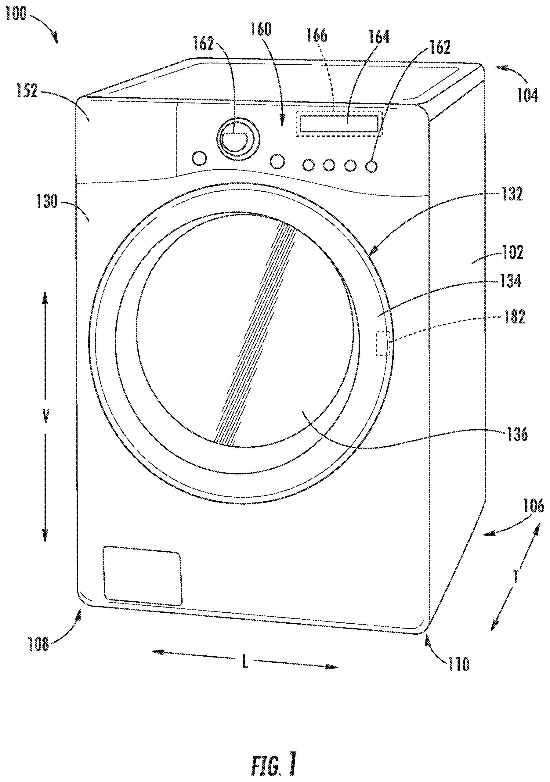
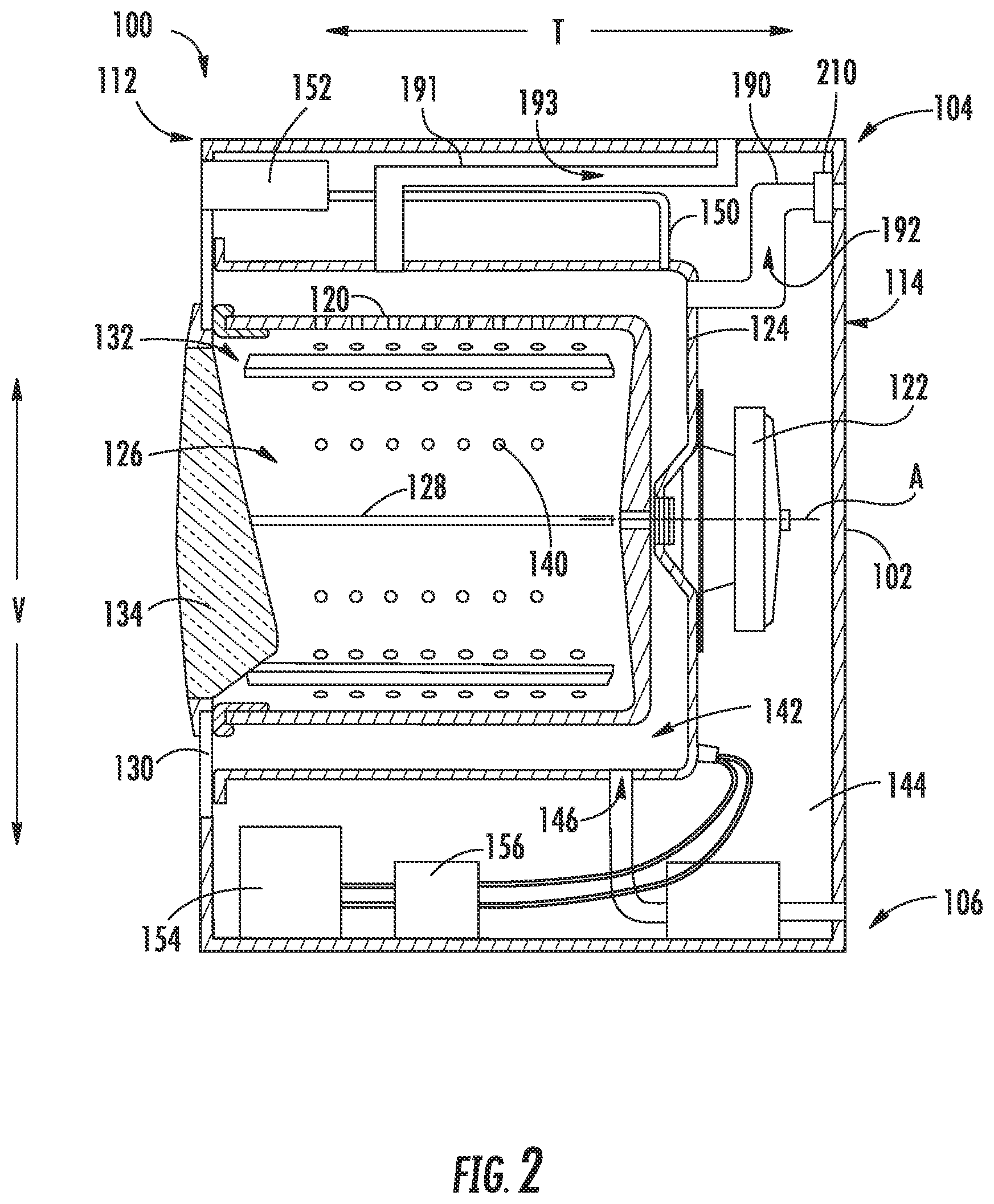
[0019] Referring now to the figures, FIG. 1 is a perspective view of an exemplary horizontal axis washing machine appliance 100, and FIG. 2 is a side cross-sectional view of washing machine appliance 100. As illustrated, washing machine appliance 100 generally defines a vertical direction V, a lateral direction L, and a transverse direction T, each of which is mutually perpendicular, such that an orthogonal coordinate system is defined. Washing machine appliance 100 includes a cabinet 102 that extends between a top 104 and a bottom 106 along the vertical direction V, between a left side 108 and a right side 110 along the lateral direction L, and between a front 112 and a rear 114 along the transverse direction T.
[0020] Referring to FIG. 2, a wash tub 124 is positioned within cabinet 102 and is generally configured for retaining wash fluids during an operating cycle. As used herein, "wash fluid" may refer to water, detergent, fabric softener, bleach, or any other suitable wash additive or combination thereof. Wash tub 124 is substantially fixed relative to cabinet 102 such that it does not rotate or translate relative to cabinet 102.
[0021] A wash basket 120 is received within wash tub 124 and defines a wash chamber 126 that is configured for receipt of articles for washing. More specifically, wash basket 120 is rotatably mounted within wash tub 124 such that it is rotatable about an axis of rotation A. According to the illustrated embodiments, the axis of rotation A is substantially parallel to the transverse direction T. In this regard, washing machine appliance 100 is generally referred to as a "horizontal axis" or "front load" washing machine appliance 100.
[0022] Wash basket 120 may define one or more agitator features that extend into wash chamber 126 to assist in agitation and cleaning articles disposed within wash chamber 126 during operation of washing machine appliance 100. For example, as illustrated in FIG. 2, a plurality of ribs 128 extends from basket 120 into wash chamber 126. In this manner, for example, ribs 128 may lift articles disposed in wash basket 120 during rotation of wash basket 120.
[0023] Washing machine appliance 100 includes a motor assembly 122 that is in mechanical communication with wash basket 120 to selectively rotate wash basket 120 (e.g., during an agitation or a rinse cycle of washing machine appliance 100). According to the illustrated embodiments, motor assembly 122 is a pancake motor. However, it should be appreciated that any suitable type, size, or configuration of motor may be used to rotate wash basket 120 according to alternative embodiments.
[0024] Referring generally to FIGS. 1 and 2, cabinet 102 also includes a front panel 130 that defines an opening 132 that permits user access to wash basket 120 of wash tub 124. More specifically, washing machine appliance 100 includes a door 134 that is positioned over opening 132 and is rotatably mounted to front panel 130 (e.g., about a door axis that is substantially parallel to the vertical direction V). In this manner, door 134 permits selective access to opening 132 by being movable between an open position (not shown) facilitating access to a wash tub 124 and a closed position (FIG. 1) prohibiting access to wash tub 124. Optionally, a lock assembly 182 may be fixed to cabinet 102 to selectively lock or hold a free end of the door 134 to cabinet 102 when door 134 is in the closed position (e.g., during certain operations or wash cycles).
[0025] In some embodiments, a window 136 in door 134 permits viewing of wash basket 120 when door 134 is in the closed position (e.g., during operation of washing machine appliance 100). Door 134 also includes a handle (not shown) that, for example, a user may pull when opening and closing door 134. Further, although door 134 is illustrated as mounted to front panel 130, it should be appreciated that door 134 may be mounted to another side of cabinet 102 or any other suitable support according to alternative embodiments. Additionally or alternatively, a front gasket or baffle may extend between tub 124 and the front panel 130 about the opening 132 covered by door 134, further sealing tub 124 from cabinet 102.
[0026] As shown, wash basket 120 defines a plurality of perforations 140 in order to facilitate fluid communication between an interior of basket 120 and wash tub 124. A sump 142 is defined by wash tub 124 at a bottom of wash tub 124 along the vertical direction V. Thus, sump 142 is configured for receipt of, and generally collects, wash fluid during operation of washing machine appliance 100. For example, during operation of washing machine appliance 100, wash fluid may be urged (e.g., by gravity) from basket 120 to sump 142 through plurality of perforations 140. A pump assembly 144 is located beneath wash tub 124 for gravity assisted flow when draining wash tub 124 (e.g., via a drain 146). Pump assembly 144 may also be configured for recirculating wash fluid within wash tub 124.
[0027] In some embodiments, washing machine appliance 100 includes an additive dispenser or spout 150. For example, spout 150 may be in fluid communication with a water supply (not shown) in order to direct fluid (e.g., clean water) into wash tub 124. Spout 150 may also be in fluid communication with the sump 142. For example, pump assembly 144 may direct wash fluid disposed in sump 142 to spout 150 in order to circulate wash fluid in wash tub 124.
[0028] As illustrated, a detergent drawer 152 may be slidably mounted within front panel 130. Detergent drawer 152 receives a wash additive (e.g., detergent, fabric softener, bleach, or any other suitable liquid or powder) and directs the fluid additive to wash chamber 126 during certain operations or wash cycle phases of washing machine appliance 100. According to the illustrated embodiment, detergent drawer 152 may also be fluidly coupled to spout 150 to facilitate the complete and accurate dispensing of wash additive.
[0029] In optional embodiments, a bulk reservoir 154 is disposed within cabinet 102. Bulk reservoir 154 may be configured for receipt of fluid additive for use during operation of washing machine appliance 100. Moreover, bulk reservoir 154 may be sized such that a volume of fluid additive sufficient for a plurality or multitude of wash cycles of washing machine appliance 100 (e.g., five, ten, twenty, fifty, or any other suitable number of wash cycles) may fill bulk reservoir 154. Thus, for example, a user can fill bulk reservoir 154 with fluid additive and operate washing machine appliance 100 for a plurality of wash cycles without refilling bulk reservoir 154 with fluid additive. A reservoir pump 156 is configured for selective delivery of the fluid additive from bulk reservoir 154 to wash tub 124.
[0030] In some embodiments, a ventilation line 190 is provided within washing machine appliance 100. In particular, ventilation line 190 may be enclosed within cabinet 102. As shown in FIG. 2, exemplary embodiments include ventilation line 190 at a position in fluid communication between tub 124 and the surrounding region (e.g., the ambient environment outside of or immediately surrounding cabinet 102, the enclosed volume of cabinet 102 surrounding tub 124, etc.). Generally, it is understood that ventilation line 190 may be provided as any suitable pipe or conduit (e.g., having non-permeable wall) for directing air therethrough. When assembled, ventilation line 190 defines an air path 192 from tub 124 and within or through cabinet 102 (e.g., to the ambient environment outside of cabinet 102). In optional embodiments, air path 192 extends from the top portion of tub 124 to an upper portion of cabinet 102. However, any other suitable configuration may be provided to facilitate the flow of air from tub 124 and, for example, to the ambient environment (e.g., when washing machine appliance 100 is not in use).
[0031] A ventilation assembly or vent damper 210 is positioned along ventilation line 190 in exemplary embodiments. Generally, vent damper 210 is in communication with ventilation line 190 (i.e., in fluid communication with air path 192). In certain embodiments, vent damper 210 is enclosed, at least in part, within cabinet 102. As will be described in detail below, vent damper 210 may be selectively controlled or operated to limit the flow of air through ventilation line 190 or air path 192 during certain operations (e.g., one or more predetermined phases or cycles). Thus vent damper 210 may selectively limit airflow between tub 124 and the ambient environment.
[0032] In certain embodiments, one or more secondary ventilation lines 191 are provided within washing machine appliance 100. In particular, a secondary ventilation line 191 may be enclosed within cabinet 102. As shown in FIG. 2, exemplary embodiments include secondary ventilation line 191 at a position in fluid communication between tub 124 and the ambient environment (e.g., the region outside of or immediately surrounding cabinet 102). Generally, it is understood that ventilation line 190 may be provided as any suitable pipe or conduit (e.g., having non-permeable wall) for directing air therethrough. When assembled, secondary ventilation line 191 defines an air path 193 from tub 124 that is distinct and separated from the air path 192. As illustrated, secondary ventilation line 191 attaches to tub 124 at a location that is spaced apart from the attachment location or point of ventilation line 190 (e.g., along the transverse direction T). In optional embodiments, air path 193 extends from the top portion of tub 124 to an upper portion of cabinet 102. However, any other suitable configuration may be provided to facilitate the flow of air from tub 124 and, for example, to the ambient environment (e.g., when washing machine appliance 100 is not in use).
[0033] When air path 192 is unobstructed (e.g., when vent damper 210 is in an open second position), air may flow through tub 124 and between air paths 192 and 193. In other words, an airflow circuit with the ambient environment may be formed by the ventilation lines 190, 191 and tub 124. Moreover, when washing machine appliance 100 is in use or air path 192 is obstructed, secondary ventilation line 191 may permit pressure within tub 124 to equalize relative to the ambient environment.
[0034] In some embodiments, a control panel 160 including a plurality of input selectors 162 is coupled to front panel 130. Control panel 160 and input selectors 162 may collectively form a user interface input for operator selection of machine cycles and features. For example, in exemplary embodiments, a display 164 indicates selected features, a countdown timer, or other items of interest to machine users.
[0035] Operation of washing machine appliance 100 is generally controlled by a controller or processing device 166. In some embodiments, controller 166 is in operative communication with (e.g., electrically or wirelessly connected to) control panel 160 for user manipulation to select washing machine cycles and features. In response to user manipulation of control panel 160, controller 166 operates the various components of washing machine appliance 100 to execute selected machine cycles and features.
[0036] Controller 166 may include a memory (e.g., non-transitive memory) and microprocessor, such as a general or special purpose microprocessor operable to execute programming instructions or micro-control code associated with a wash operation. The memory may represent random access memory such as DRAM, or read only memory such as ROM or FLASH. In one embodiment, the processor executes programming instructions stored in memory. The memory may be a separate component from the processor or may be included onboard within the processor. Alternatively, controller 166 may be constructed without using a microprocessor (e.g., using a combination of discrete analog or digital logic circuitry, such as switches, amplifiers, integrators, comparators, flip-flops, AND gates, and the like) to perform control functionality instead of relying upon software. Control panel 160 and other components of washing machine appliance 100, such as motor assembly 122 and vent damper 210, may be in operative communication with controller 166 via one or more signal lines or shared communication busses. Additionally or alternatively, other features, such as an electronic lock assembly 182 for door 134 may be in operative communication with controller 166 via one or more other signal lines or shared communication busses.
[0037] In exemplary embodiments, during operation of washing machine appliance 100, laundry items are loaded into wash basket 120 through opening 132, and a wash cycle is initiated through operator manipulation of input selectors 162. For example, a wash cycle may be initiated such that wash tub 124 is filled with water, detergent, or other fluid additives (e.g., via additive dispenser 150 during a fill phase). One or more valves (not shown) can be controlled by washing machine appliance 100 to provide for filling wash basket 120 to the appropriate level for the amount of articles being washed or rinsed. By way of example, once wash basket 120 is properly filled with fluid, the contents of wash basket 120 can be agitated (e.g., with ribs 128) for an agitation phase of laundry items in wash basket 120. During the agitation phase, the basket 120 may be motivated about the axis of rotation A at a set speed (e.g., first speed or tumble speed). As the basket 120 is rotated, articles within the basket 120 may be lifted and permitted to drop therein.
[0038] After the agitation phase of the washing operation or wash cycle is completed, wash tub 124 can be drained (e.g., through a drain phase). Laundry articles can then be rinsed (e.g., through a rinse phase) by again adding fluid to wash tub 124, depending on the particulars of the wash cycle selected by a user. Ribs 128 may again provide agitation within wash basket 120. One or more spin phases may also be used. In particular, a spin phase may be applied after the wash cycle or after the rinse cycle in order to wring wash fluid from the articles being washed. During a spin phase, basket 120 is rotated at relatively high speeds. For instance, basket 120 may be rotated at one set speed (e.g., second speed or pre-plaster speed) before be rotated at another set speed (e.g., third speed or plaster speed). As would be understood, the pre-plaster speed may be greater than the tumble speed and the plaster speed may be greater than the pre-plaster speed. Moreover, agitation or tumbling of articles may be reduced as basket 120 increases its rotational velocity such that the plaster speed maintains the articles at a generally fixed position relative to basket 120.
[0039] After articles disposed in wash basket 120 are cleaned (or the wash cycle otherwise ends), a user can remove the articles from wash basket 120 (e.g., by opening door 134 and reaching into wash basket 120 through opening 132).
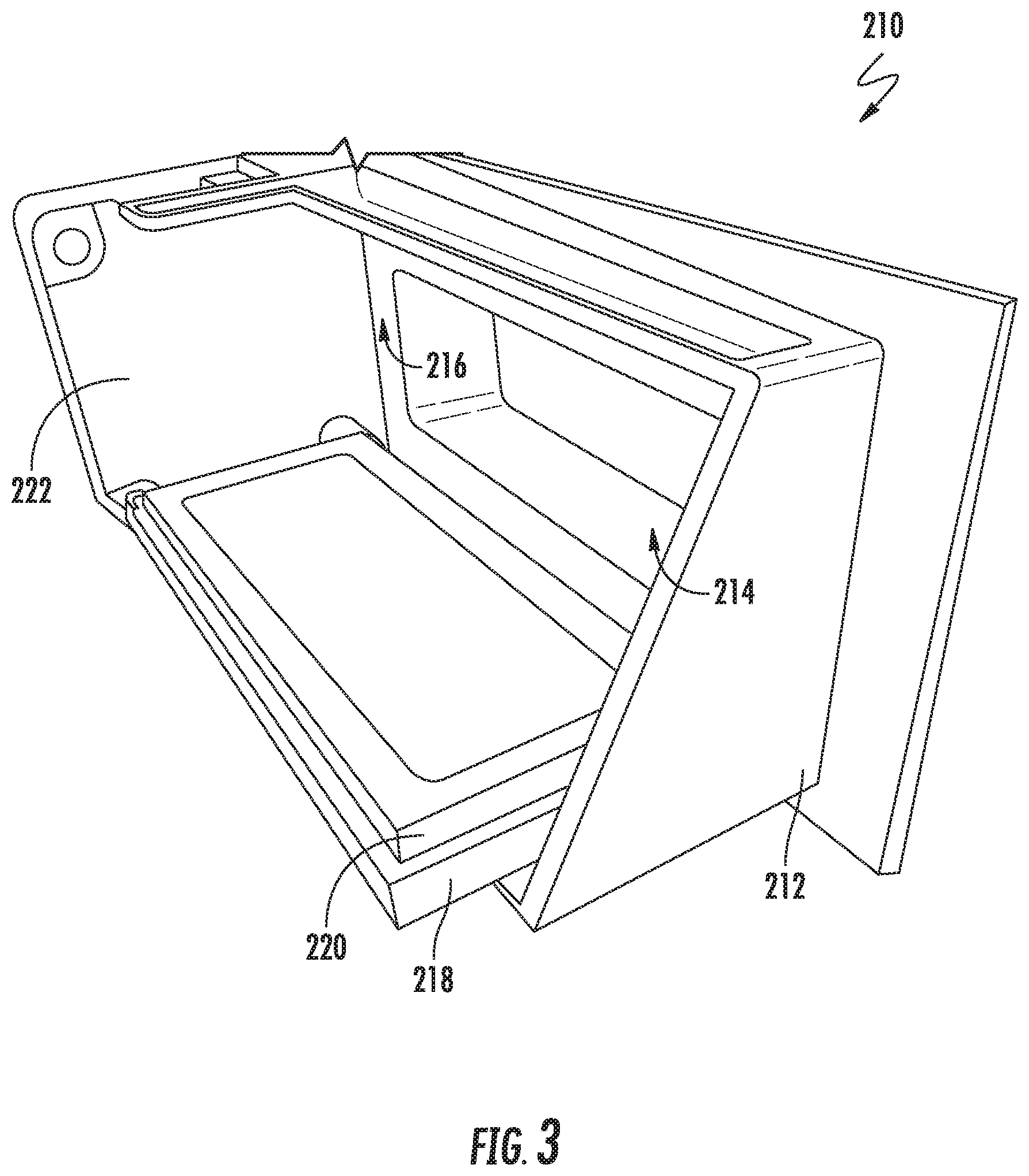
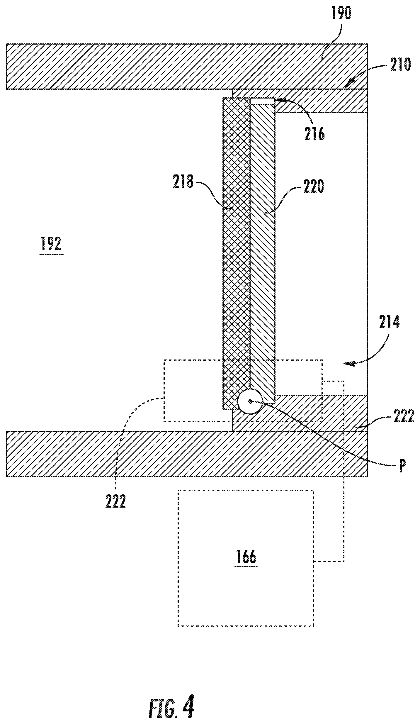
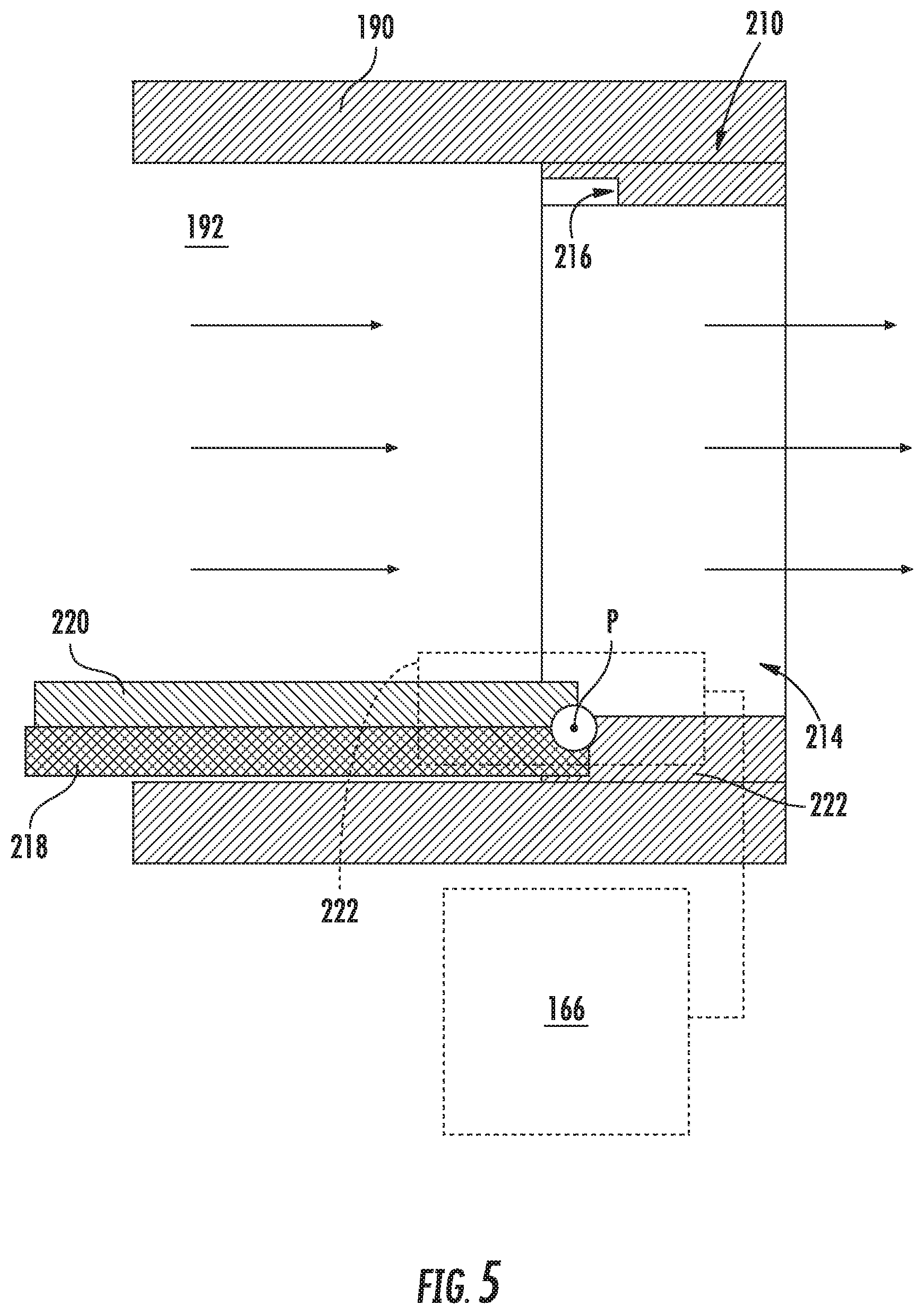
[0040] Turning now to FIGS. 3 through 5, various views are provided of a damper assembly (e.g., vent damper 210) according to exemplary embodiments of the present disclosure. As shown, vent damper 210 may include a rigid, non-permeable housing or chute 212. Chute 212 may define an opening 214 to selectively permit air therethrough and communicate with air path 192. Thus, chute 212 may extend about opening 214, and opening 214 may extend through chute 212. In certain embodiments, an interior lip 216 extends radially inward from chute 212 toward opening 214 (e.g., coaxial or concentric with opening 214), thus defining a perimeter (or perimeter portion) of opening 214.
[0041] When assembled, chute 212 may be positioned along within ventilation line 190. Ventilation line 190 may be mated to chute 212. For instance, the walls ventilation line 190 may connect directly or indirectly to chute 212. Opening 214 may thus be aligned with air path 192. It is understood that when assembled airflow through the air path 192 is restricted through opening 214. Thus, any air passing between tub 124 and the ambient environment through ventilation line 190 may be forced to flow through opening 214. This may be especially true when door 134 (FIG. 2) of the washing machine appliance 100 is in the closed position.
[0042] In some embodiments, vent damper 210 includes a non-permeable restrictor plate 218. Generally, restrictor plate 218 is movably attached to chute 212. For example, restrictor plate 218 may be rotatably mounted to chute 212 to selectively pivot about a predefined pivot axis P. During use, restrictor plate 218 may be selectively moved (e.g., rotated) in front of or behind opening 214. Thus, restrictor plate 218 may selectively block air passage through opening 214. Moreover, restrictor plate 218 may selectively permit air passage through opening 214.
[0043] In certain embodiments, restrictor plate 218 is configured to move between a discrete first position and second position. As illustrated in FIG. 4, the first position generally restricts airflow through opening 214 (e.g., and thereby through ventilation line 190). In the first position, restrictor plate 218 may extend across opening 214. By contrast, and as illustrated in FIG. 5, the second position may generally permit airflow through opening 214 (e.g., and thereby through ventilation line 190). In the second position, restrictor plate 218 may be moved away from opening 214 (e.g., to a positioning that is parallel or nonorthogonal to air path 192).
[0044] In certain embodiments, a resilient foam layer 220 is provided on restrictor plate 218. For instance, resilient foam layer 220 may be fixed to a surface of restrictor plate 218 between opening 214 and restrictor plate 218 (e.g., relative to or along air path 192). When restrictor plate 218 is in the first position, resilient foam layer 220 may contact at least a portion of chute 212. For instance, resilient foam layer 220 may be positioned in contact with interior lip 216. Optionally, resilient foam layer 220 may be at least partially compressed against chute 212, sealing air path 192 to prevent air from passing through opening 214. It is understood that resilient foam layer 220 may be provided as any suitable resilient or elastic foam material that can be compressed before returning to its uncompressed state or shape.
[0045] In exemplary embodiments, a motor 222 is mechanically coupled to non-permeable restrictor plate 218. Motor 222 may be attached at any suitable location on or near chute 212 to move restrictor plate 218 relative to opening 214. For instance, motor 222 may be configured to selectively rotate restrictor plate 218 about the pivot access P. Moreover, motor 222 may be provided as any suitable electromechanical device (e.g., gear assembly, solenoid, actuator, etc.) for moving restrictor plate 218 or holding restrictor plate 218 in a directed position. In certain embodiments, motor 222 is in operative communication with (e.g., electrically or wirelessly connected to) controller 166. Controller 166 may be configured to direct motor 222 to move or hold restrictor plate 218 in a selected position (e.g., according to a selected wash cycle or phase). In other words, controller 166 may be configured to move or rotate vent damper 210 between the first position and the second position.
[0046] Referring now to FIG. 6, various methods may be provided for use with washing machine appliances in accordance with the present disclosure. In general, the various steps of methods as disclosed herein may, in exemplary embodiments, be performed by the controller 166, which may receive inputs and transmit outputs from various other components of the appliance 100. In particular, the present disclosure is further directed to methods, as indicated by reference number 600, for operating a washing machine appliance 100, as described above. Such methods advantageously facilitate selectively limiting the audible noise transmitted outside of washing machine appliance (e.g., outside of cabinet 102 in the surrounding ambient environment) during a wash cycle.
[0047] As shown in FIG. 6, at 610, the method 600 includes receiving a user input at the washing machine appliance. For instance, the controller may receive a signal in response to user command provided at the user interface (e.g., to activate the washing machine appliance from a sleep state, select a wash cycle, etc.). Optionally, a wash cycle may be initiated, as discussed above. Additionally or alternatively, the door the washing machine appliance may be locked or unlocked (e.g., at the lock assembly) depending on the received user input.
[0048] At 620, the method 600 includes determining a noise state of the washing machine appliance following receiving the user input (i.e., following 610). Moreover, 620 may be based on (or otherwise contingent upon) the user input at 610.
[0049] As an example, the noise state may generally correspond to the initiation or completion of a wash cycle. In some such embodiments, 620 includes determining initiation of a wash cycle (i.e., when a wash cycle has begun or is otherwise imminent) such that significant noise can be expected from within the washing machine appliance. In additional or alternative embodiments, 620 includes determining completion of a wash cycle (i.e., when a wash cycle has ended) such that significant noise is no longer being generated by the basket motor, water valves, or basket within the washing machine appliance. Optionally, the method 600 may include multiple noise state determinations. For instance one noise state determination may be made upon determining initiation of a wash cycle, while another noise state determination may be made upon determining completion of the wash cycle.
[0050] As another example, the noise state may generally correspond to one or more sub-portions or phases of a wash cycle during which significant noise is expected. In some such embodiments, 620 includes determining initiation of an audible phase of the wash cycle (i.e., when an audible phase has begun, is beginning, or is otherwise imminent). In additional or alternative embodiments, 620 includes determining completion of an audible phase of a wash cycle (i.e., when an audible phase has ended) such that significant noise is no longer being generated by the basket motor, water valves, or basket within the washing machine appliance. The audible phase may include one or more of the fill phase, agitation phase, or spin phase, as discussed above. Optionally, the method 600 may include multiple noise state determinations. For instance one noise state determination may be made upon determining initiation of an audible phase of a wash cycle, while another noise state determination may be made upon determining completion of the audible phase of the wash cycle.
[0051] As yet another example, the noise state may generally correspond to a standby condition or a wake condition. Generally, the standby condition may be provided as a low-power state wherein at least a portion of washing machine appliance (e.g., the user interface or the display) is inactive, such as after a predetermined amount of time during which no user input is received and no wash cycle is being performed. The wake condition may be provided as a condition that prompts the washing machine appliance out of a standby condition (e.g., engagement of a predetermined user input at the input selectors). In some such embodiments, 620 includes determining a wake condition is met. For instance, determining the wake condition is met may include determining that the washing machine appliance has received a user input prompting the washing machine appliance to activate one or more elements that were rendered inactive during a standby condition. In additional or alternative embodiments, 620 includes determining a standby condition is met. For instance, determining that the standby condition is met may include determining that the washing machine appliance has deactivated one or more elements in response to a predetermined time period of non-use. Optionally, the method 600 may include multiple noise state determinations. For instance one noise state determination may be made upon determining a wake condition is met, while another noise state determination may be made upon determining a standby condition is met.
[0052] As still another example, the noise state may generally correspond to a lock condition or unlock condition for the door of the appliance (e.g., at the lock assembly). Generally, the lock condition may hold door in the closed position as the lock assembly secures the door to the cabinet. The unlock condition may permit the door to move between a closed position and an open position as the lock assembly releases a free end of the door from the cabinet. In some such embodiments, 620 includes determining a lock condition is met. For instance, determining the lock condition is met may include determining that the lock assembly has been or is actively being directed to hold the door of washing machine appliance closed (e.g., against the cabinet). In additional or alternative embodiments, 620 includes determining an unlock condition is met. For instance, determining that the unlock condition is met may include determining that the lock assembly has been or is actively being directed to release the free end of the door from the cabinet. Optionally, the method 600 may include multiple noise state determinations. For instance one noise state determination may be made upon determining a lock condition is met, while another noise state determination may be made upon determining an unlock condition is met.
[0053] At 630, the method 600 includes directing the vent damper between a first position and a second position based on the determined noise state, as described above.
[0054] As an example, if the noise state corresponds to the wash cycle, the vent damper may be directed accordingly. In some such embodiments, 630 includes placing the vent damper in the first position (e.g., moving the vent damper to or holding the vent damper at the first position) in response to initiation of the wash cycle. In additional or alternative embodiments, 630 includes placing the vent damper in the second position (e.g., moving the vent damper to or holding the vent damper at the second position) in response to completion of the wash cycle.
[0055] As another example, if the noise state corresponds to the audible phase, the vent damper may be directed accordingly. In some such embodiments, 630 includes placing the vent damper in the first position (e.g., moving the vent damper to or holding the vent damper at the first position) in response to initiation of the audible phase. In additional or alternative embodiments, 630 includes placing the vent damper in the second position (e.g., moving the vent damper to or holding the vent damper at the second position) in response to completion of the audible phase.
[0056] As yet another example, if the noise state corresponds to the wake condition or standby condition, the vent damper may be directed accordingly. In some such embodiments, 630 includes placing the vent damper in the first position (e.g., moving the vent damper to or holding the vent damper at the first position) in response to the wake condition being met. In additional or alternative embodiments, 630 includes placing the vent damper in the second position (e.g., m moving the vent damper to or holding the vent damper at the second position) in response to the standby condition being met.
[0057] As still another example, if the noise state corresponds to the door lock condition or door unlock condition, the vent damper may be directed accordingly. In some such embodiments, 630 includes placing the vent damper in the first position (e.g., moving the vent damper to or holding the vent damper at the first position) in response to the door lock condition being met. In additional or alternative embodiments, 630 includes placing the vent damper in the second position (e.g., moving the vent damper to or holding the vent damper at the second position) in response to the door unlock condition being met.
[0058] This written description uses examples to disclose the invention, including the best mode, and also to enable any person skilled in the art to practice the invention, including making and using any devices or systems and performing any incorporated methods. The patentable scope of the invention is defined by the claims, and may include other examples that occur to those skilled in the art. Such other examples are intended to be within the scope of the claims if they include structural elements that do not differ from the literal language of the claims, or if they include equivalent structural elements with insubstantial differences from the literal languages of the claims.
* * * * *
D00000
D00001
D00002
D00003
D00004
D00005
D00006
XML
uspto.report is an independent third-party trademark research tool that is not affiliated, endorsed, or sponsored by the United States Patent and Trademark Office (USPTO) or any other governmental organization. The information provided by uspto.report is based on publicly available data at the time of writing and is intended for informational purposes only.
While we strive to provide accurate and up-to-date information, we do not guarantee the accuracy, completeness, reliability, or suitability of the information displayed on this site. The use of this site is at your own risk. Any reliance you place on such information is therefore strictly at your own risk.
All official trademark data, including owner information, should be verified by visiting the official USPTO website at www.uspto.gov. This site is not intended to replace professional legal advice and should not be used as a substitute for consulting with a legal professional who is knowledgeable about trademark law.