Acoustic Wave Based Particle Agglomeration
Friend; James ; et al.
U.S. patent application number 16/461753 was filed with the patent office on 2019-11-28 for acoustic wave based particle agglomeration. The applicant listed for this patent is The Regents of the University of California. Invention is credited to James Friend, Yuta Kurashina, Kenjiro Takemura.
| Application Number | 20190359968 16/461753 |
| Document ID | / |
| Family ID | 62146681 |
| Filed Date | 2019-11-28 |


View All Diagrams
| United States Patent Application | 20190359968 |
| Kind Code | A1 |
| Friend; James ; et al. | November 28, 2019 |
ACOUSTIC WAVE BASED PARTICLE AGGLOMERATION
Abstract
Articles of manufacture, including an apparatus for acoustic wave based agglomeration, are provided. The apparatus may include a well and an acoustic wave device. The well may be configured to hold a suspension that includes a plurality of particles. The acoustic wave device may be configured to generate a plurality of acoustic waves. The plurality of acoustic waves inducing acoustic streaming within the suspension. The acoustic streaming agitating the suspension to form an agglomerate comprising at least a portion of the plurality of particles. Methods for acoustic wave based agglomeration are also provided.
| Inventors: | Friend; James; (San Diego, CA) ; Takemura; Kenjiro; (Yokohama, JP) ; Kurashina; Yuta; (Yokohama, JP) | ||||||||||
| Applicant: |
|
||||||||||
|---|---|---|---|---|---|---|---|---|---|---|---|
| Family ID: | 62146681 | ||||||||||
| Appl. No.: | 16/461753 | ||||||||||
| Filed: | November 17, 2017 | ||||||||||
| PCT Filed: | November 17, 2017 | ||||||||||
| PCT NO: | PCT/US17/62256 | ||||||||||
| 371 Date: | May 16, 2019 |
Related U.S. Patent Documents
| Application Number | Filing Date | Patent Number | ||
|---|---|---|---|---|
| 62424098 | Nov 18, 2016 | |||
| Current U.S. Class: | 1/1 |
| Current CPC Class: | C12M 47/02 20130101; B06B 1/06 20130101; C12N 13/00 20130101; B06B 2201/77 20130101; B06B 1/0603 20130101; C05B 19/00 20130101; B06B 1/0215 20130101 |
| International Class: | C12N 13/00 20060101 C12N013/00; C12M 1/00 20060101 C12M001/00; B06B 1/02 20060101 B06B001/02; B06B 1/06 20060101 B06B001/06 |
Claims
1. An apparatus, comprising: a well including a suspension comprising a plurality of particles; and an acoustic wave device configured to generate a plurality of acoustic waves, the plurality of acoustic waves inducing acoustic streaming within the suspension, and the acoustic streaming agitating the suspension to form an agglomerate comprising at least a portion of the plurality of particles.
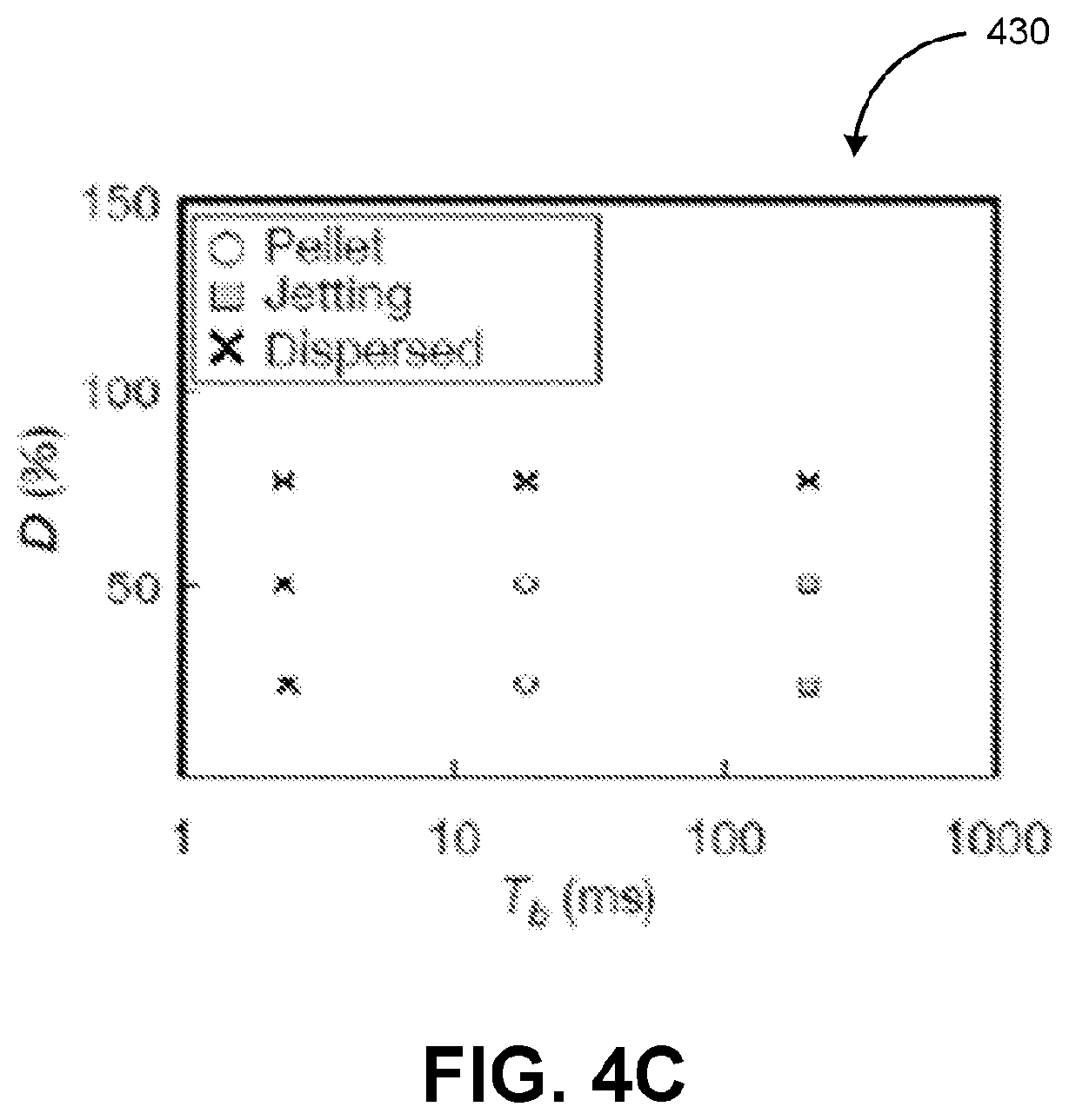
2. The apparatus of claim 1, wherein the agglomerate comprises a 3-dimensional formation comprising at least the portion of the plurality of particles.
3. The apparatus of claim 1, wherein the plurality of particles comprise cells.
4. The apparatus of claim 1, wherein the suspension comprises a mixture of the plurality of particles and one or more fluids.
5. The apparatus of claim 1, wherein the acoustic wave device comprises a piezoelectric material configured to convert electric energy into the plurality of acoustic waves.
6. The apparatus of claim 5, wherein the piezoelectric material comprises a monocrystalline and/or a polycrystalline.
7. The apparatus of claim 5, wherein 50 milliwatts to 5.0 watts of electric power is applied to the piezoelectric material in order to cause the acoustic wave device to generate the plurality of acoustic waves.
8. The apparatus of claim 1, wherein the acoustic wave device is configured to generate the plurality of acoustic waves in one or more intermittent bursts.
9. The apparatus of claim 8, wherein a length of the one or more intermittent bursts of acoustic waves is between 1 second and 100 seconds.
10. The apparatus of claim 8, wherein each of the one or more intermittent bursts of acoustic waves triggers a corresponding cycle of the acoustic streaming.
11. The apparatus of claim 10, wherein the acoustic wave device is configured to expose the suspension to between 1 cycle to 1000 cycles of the acoustic streaming, and wherein each cycle of the acoustic streaming is between 0.1 seconds per minute to 15 seconds per minute.
12. The apparatus of claim 1, wherein the acoustic wave device is configured to operate in accordance with a duty ratio, and wherein the duty ratio corresponds to a proportion of total elapsed time during which the acoustic wave device is generating the plurality of acoustic waves.
13. The apparatus of claim 12, wherein the duty ratio is between 10% and 50%.
14. The apparatus of claim 1, wherein the apparatus further comprises a couplant material configured to transmit the plurality of acoustic waves from the acoustic wave device to the well.
15. The apparatus of claim 1, wherein the acoustic wave device is oriented such that the plurality of acoustic waves enters a bottom of the well at between an 5.degree. angle of incidence and an 55.degree. angle of incidence.
16. The apparatus of claim 1, wherein the acoustic wave device is oriented such that the acoustic streaming is induced at between 1/2 to 3/4 of a distance between a center of the well and an edge of the well.
17. A method, comprising generating, by an acoustic wave device, a plurality of acoustic waves, the plurality of acoustic waves inducing acoustic streaming within a suspension comprising a plurality of particles, the suspension being included in a well, and the acoustic streaming agitating the suspension to form an agglomerate comprising at least a portion of the plurality of particles.
18. The method of claim 17, wherein the agglomerate comprises a 3-dimensional formation comprising at least the portion of the plurality of particles.
19-32. (canceled)
Description
RELATED APPLICATION
[0001] This application claims priority to U.S. Provisional Patent Application No. 62/424,098 file on Nov. 18, 2016 and entitled SPHEROID FABRICATION IN WELL TRAYS USING ULTRASOUND, the disclosure of which is incorporated herein by reference in its entirety.
TECHNICAL FIELD
[0002] The subject matter described herein relates generally to tissue engineering and more specifically to techniques for forming cell agglomerates.
BACKGROUND
[0003] A cell agglomerate may refer to a three-dimensional cell formation such as, for example, a spheroid of cells. Cell agglomerates may provide a more realistic representation of an in vivo environment than two-dimensional cell formations such as, for example, a monolayer of cells. As such, cell agglomerates may have a variety of clinical and research applications. For example, cancerous cell agglomerates that replicate tumors may be used in the development of treatments such as, for instance, chemotherapy, radiation therapy, and/or the like. In doing so, these cell agglomerates may provide an exemplary in vitro supplement and/or alternative to animal testing.
SUMMARY
[0004] Articles of manufacture, including apparatuses, and methods for acoustic wave based agglomeration are provided. An apparatus for acoustic wave based agglomeration may include a well and an acoustic wave device. The well may hold a suspension that includes a plurality of particles. The acoustic wave device may be configured to generate a plurality of acoustic waves. The plurality of acoustic waves may induce acoustic streaming within the suspension. The acoustic streaming may agitate the suspension to form an agglomerate comprising at least a portion of the plurality of particles.
[0005] In some variations, one or more features disclosed herein including the following features can optionally be included in any feasible combination. The agglomerate may be a 3-dimensional formation that includes at least the portion of the plurality of particles. The plurality of particles may be cells. The suspension may be a mixture of the plurality of particles and one or more fluids.
[0006] In some variations, the acoustic wave device may include a piezoelectric material configured to convert electric energy into the plurality of acoustic waves. The piezoelectric material may include a monocrystalline and/or a polycrystalline. In order to cause the acoustic wave device to generate the plurality of acoustic waves, between 50 milliwatts to 5.0 watts of electric power may be applied to the acoustic wave device.
[0007] In some variations, the acoustic wave device may be configured to generate the plurality of acoustic waves in one or more intermittent bursts. A length of the one or more intermittent bursts of acoustic waves may be between 1 second and 100 seconds. Each of the one or more intermittent bursts of acoustic waves may trigger a corresponding cycle of the acoustic streaming. The acoustic wave device may be configured to expose the suspension to between 1 cycle and 1000 cycles of the acoustic streaming. Each cycle of the acoustic streaming may be between 0.1 seconds per minute to 15 seconds per minute
[0008] In some variations, the acoustic wave device may be configured to operate in accordance with a duty ratio. The duty ratio may correspond to a proportion of total elapsed time during which the acoustic wave device is generating the plurality of acoustic waves. The duty ratio may be between 10% and 50%.
[0009] In some variations, the apparatus may further include a couplant material configured to transmit the plurality of acoustic waves from the acoustic wave device to the well. The acoustic wave device may be oriented such that the plurality of acoustic waves enters a bottom of the well at between an 5.degree. angle of incidence and an 55.degree. angle of incidence. The acoustic wave device may be oriented such that the acoustic streaming is induced at between 1/2 to 3/4 of a distance between from a center of the well and an edge of the well.
[0010] A method for acoustic wave based agglomeration includes generating, by an acoustic wave device, a plurality of acoustic waves. The plurality of acoustic waves may induce acoustic streaming within a suspension comprising a plurality of particles. The suspension may be held in a well. The acoustic streaming may agitate the suspension to form an agglomerate that includes at least a portion of the plurality of particles
[0011] In some variations, one or more features disclosed herein including the following features can optionally be included in any feasible combination. The agglomerate may be a 3-dimensional formation that includes at least the portion of the plurality of particles. The plurality of particles may be cells. The suspension may be a mixture of the plurality of particles and one or more fluids.
[0012] In some variations, a piezoelectric material included in the acoustic wave device may convert electric energy into the plurality of acoustic waves. In order to cause the acoustic wave device to generate the plurality of acoustic waves, between 50 milliwatts and 3.0 watts of power may be applied to the piezoelectric material.
[0013] In some variations, the acoustic wave device may generate the plurality of acoustic waves in one or more intermittent bursts. A length of the one or more intermittent bursts of acoustic waves is between 1 second and 100 seconds. Each of the one or more intermittent bursts of acoustic waves may trigger a corresponding cycle of acoustic streaming. The acoustic wave device may expose the suspension to between 1 cycle and 1000 cycles of the acoustic streaming. Each cycle of the acoustic streaming may be between 0.1 seconds per minute to 15 seconds per minute.
[0014] In some variations, the acoustic wave device may be operated in accordance with a duty ratio corresponding to a proportion of total elapsed time during which the acoustic wave device is generating the plurality of acoustic waves. The duty ratio may be between 10% and 50%.
[0015] In some variations, the plurality of acoustic waves may be transmitted from the acoustic wave device to the well via a couplant material. The acoustic wave device may be oriented such that the plurality of acoustic waves enters a bottom of the well at between an 5.degree. angle of incidence and an 55.degree. angle of incidence. The acoustic wave device may be oriented such that the acoustic streaming is induced at between 1/2 to 3/4 of a distance between a center of the well and an edge of the well.
[0016] The details of one or more variations of the subject matter described herein are set forth in the accompanying drawings and the description below. Other features and advantages of the subject matter described herein will be apparent from the description and drawings, and from the claims. While certain features of the currently disclosed subject matter are described for illustrative purposes in relation to a rechargeable battery, it should be readily understood that such features are not intended to be limiting. The claims that follow this disclosure are intended to define the scope of the protected subject matter.
DESCRIPTION OF DRAWINGS
[0017] The accompanying drawings, which are incorporated in and constitute a part of this specification, show certain aspects of the subject matter disclosed herein and, together with the description, help explain some of the principles associated with the disclosed implementations. In the drawings,
[0018] FIG. 1A depicts a perspective view of an apparatus for acoustic wave based agglomeration, in accordance with some example embodiments;
[0019] FIG. 1B depicts a side view of an apparatus for acoustic wave based agglomeration, in accordance with some example embodiments,
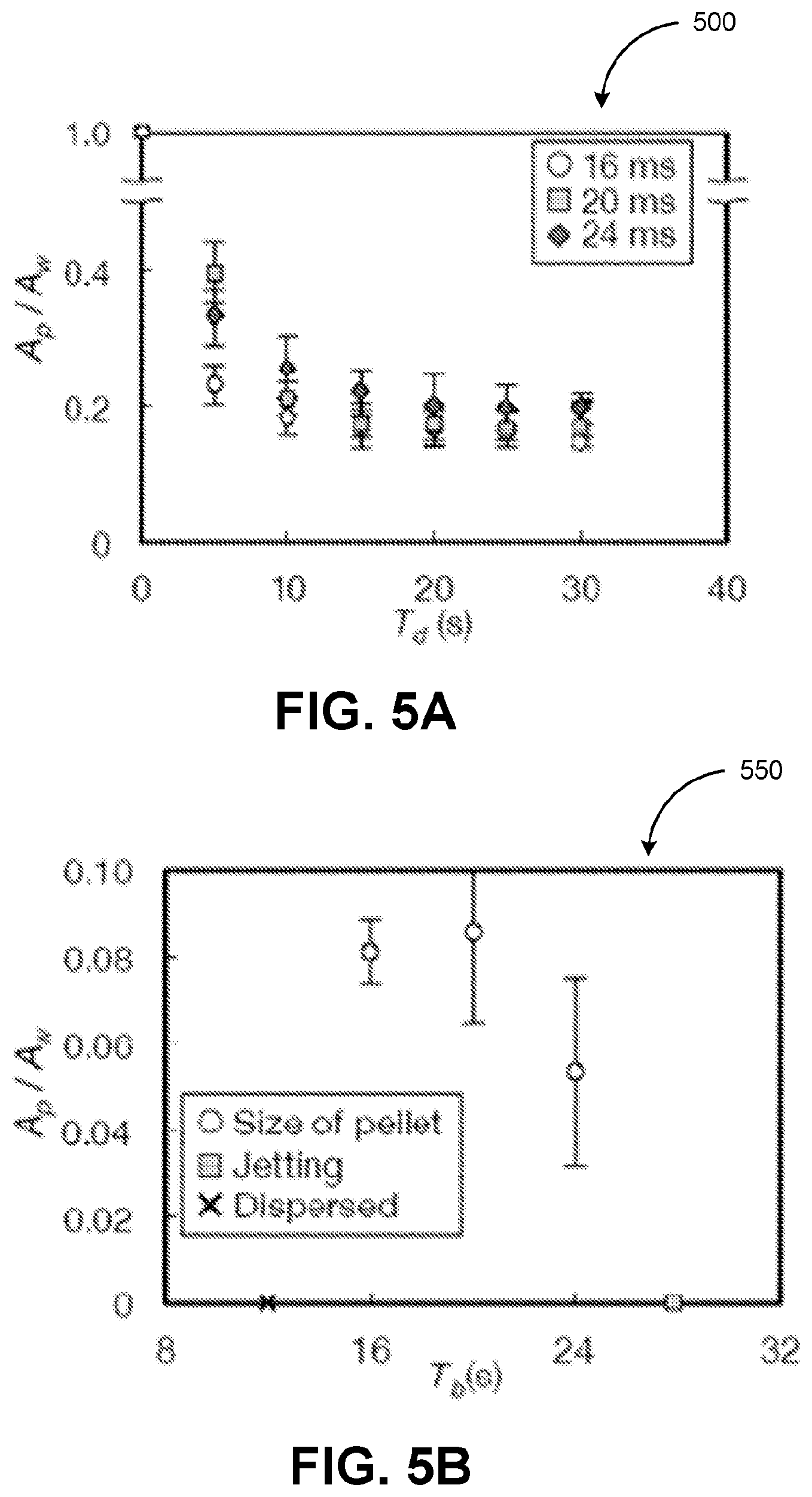
[0020] FIG. 1C depicts a top view of an apparatus for acoustic wave based agglomeration, in accordance with some example embodiments;
[0021] FIG. 2A depicts a graph illustrating agglomerate formation at different angles of incidence, in accordance to some example embodiments;
[0022] FIG. 2B depicts a graph illustrating agglomerate formation at different angles of incidence, in accordance to some example embodiments;
[0023] FIG. 2C depicts an image of an agglomerate formed at a 20.degree. angle of incidence, in accordance with some example embodiments;
[0024] FIG. 2D depicts an image of an agglomerate formed at a 25.degree. angle of incidence, in accordance with some example embodiments;
[0025] FIG. 2E depicts an image of an agglomerate formed at a 30.degree. angle of incidence, in accordance with some example embodiments;
[0026] FIG. 3A depicts a graph illustrating agglomerate formation at different radial locations, in accordance to some example embodiments;
[0027] FIG. 3B depicts a graph illustrating agglomerate formation at different radial locations, in accordance to some example embodiments;
[0028] FIG. 3C depicts an image of an agglomerate formed with a 0 millimeter radial location, in accordance with some example embodiments;
[0029] FIG. 3D depicts an image of an agglomerate formed with a 2.5 millimeter, in accordance with some example embodiments;
[0030] FIG. 3E depicts an image of an agglomerate formed with a 5.0 millimeter radial location, in accordance with some example embodiments;
[0031] FIG. 3F depicts an image of an agglomerate formed with a 7.5 millimeter radial location, in accordance with some example embodiments;
[0032] FIG. 4A depicts a graph illustrating agglomerate formation at different duty ratios and input powers, in accordance to some example embodiments;
[0033] FIG. 4B depicts a graph illustrating agglomerate formation at a fixed input power with different duty ratios and lengths of burst periods, in accordance to some example embodiments;
[0034] FIG. 4C depicts a graph illustrating agglomerate formation at a fixed input power with different duty ratios and lengths of burst period, in accordance with some example embodiments;
[0035] FIG. 4D depicts an image of an agglomerate formed with an input power of 0.75 watts and a duty ratio of 25%, in accordance with some example embodiments;
[0036] FIG. 4E depicts an image of an agglomerate formed with an input power of 1.5 watts and a duty ratio of 25%, in accordance with some example embodiments;
[0037] FIG. 4F depicts an image of an agglomerate formed with an input power of 1.5 watts and a duty ratio of 50%, in accordance with some example embodiments;
[0038] FIG. 5A depicts a graph illustrating agglomerate formation at different length burst periods, in accordance to some example embodiments;
[0039] FIG. 5B depicts a graph illustrating agglomerate formation at different lengths burst periods, in accordance to some example embodiments;
[0040] FIG. 5C depicts an image of an agglomerate formed with 16-millisecond burst period, in accordance with some example embodiments;
[0041] FIG. 5D depicts an image of an agglomerate formed with a 20-millisecond burst period, in accordance with some example embodiments;
[0042] FIG. 5E depicts an image of an agglomerate formed with a 24-millisecond burst period, in accordance with some example embodiments;
[0043] FIG. 6A depicts a graph illustrating agglomerate formation at different concentrations of solid particles, in accordance to some example embodiments;
[0044] FIG. 6B depicts a graph illustrating agglomerate formation at different concentrations of solid particles, in accordance to some example embodiments;
[0045] FIG. 6C depicts an image of an agglomerate formed at a concentration of 1.0.times.10.sup.3 particles per milliliter, in accordance with some example embodiments;
[0046] FIG. 6D depicts an image of an agglomerate formed at a concentration of 5.0.times.10.sup.3 particles per milliliter, in accordance with some example embodiments;
[0047] FIG. 6E depicts an image of an agglomerate formed at a concentration of 1.0.times.10.sup.4 particles per milliliter, in accordance with some example embodiments;
[0048] FIG. 6F depicts an image of an agglomerate formed at a concentration of 5.0.times.10.sup.4 particles per milliliter, in accordance with some example embodiments;
[0049] FIG. 6G depicts an image of an agglomerate formed at a concentration of 1.0.times.10.sup.5 particles per milliliter, in accordance with some example embodiments;
[0050] FIG. 7A depicts a graph illustrating agglomerate formation at different lengths exposure cycles, in accordance with some example embodiments;
[0051] FIG. 7B depicts an image of an agglomerate formed with a 3 second per minute exposure cycle, in accordance with some example embodiments;
[0052] FIG. 7C depicts an image of an agglomerate formed with a 10 second per minute exposure cycle, in accordance with some example embodiments;
[0053] FIG. 8 depicts a flowchart illustrating a process for acoustic wave based agglomeration, in accordance with some example embodiments.
[0054] When practical, similar reference numbers denote similar structures, features, and/or elements.
DETAILED DESCRIPTION
[0055] Despite the many clinical and research applications for cell agglomerates, conventional techniques for forming cell agglomerates may not be viable for high volume production of quality cell agglomerates. For instance, cell agglomerates may be formed by stirring a cell culture with a spinner flask, but the resulting cell agglomerates may be inconsistent in size. Other techniques for forming cell agglomerates such as, for example, micromolding and hanging-drop, may yield cell agglomerates that are uniform in size. However, these agglomeration techniques may be cost prohibitive due to technical complexities such as, for example, the requirement for agarose gels cast from three-dimensional printed micromolds, microarrays made via photopolymerization, and/or micropatterns generated on an inverted polydimethyl-siloxane substrate. As such, in some example embodiments, cell agglomerates may be formed by at least exposing cells to ultrasonic energy such as, for example, acoustic waves and/or the like.
[0056] In some example embodiments, an apparatus for acoustic wave based agglomeration may include one or more wells for holding a suspension, which may be a heterogeneous mixture that includes a fluid and a plurality of solid particles such as cells. The apparatus for acoustic wave based agglomeration may further include an acoustic wave device configured to generate a plurality of acoustic waves. The acoustic wave device may include a piezoelectric material such as, for example, a monocrystalline (e.g., lithium niobate, quartz, lithium tantalate, langasite, and/or the like), a polycrystalline (e.g., ceramic and/or the like), and/or the like. As such, the acoustic wave device may generate the plurality of acoustic waves as a response to being subject to an electric field. The plurality of acoustic waves generated by the acoustic wave device may be delivered to the one or more wells via a couplant material configured to enable the transmission of ultrasonic energy such as, for example, acoustic waves and/or the like. The plurality of acoustic waves may generate, within each of the one or more wells, a vortex that causes the suspended particles (e.g., cells) to form agglomerations such as, for example, spheroids and/or the like. It should be appreciated that the use of acoustic waves may produce uniformly sized cell agglomerations that are substantially (e.g., 15 times) larger than cell agglomerations formed using conventional agglomeration techniques. These larger cell agglomerations may be more viable test specimen than the smaller cell agglomerations generated using conventional agglomeration techniques.
[0057] FIGS. 1A-C depict an apparatus 100 for acoustic wave based agglomeration, in accordance with some example embodiments. Referring to FIGS. 1A-C, the apparatus 100 may include an acoustic wave device 120. The apparatus 100 may further include one or more wells including, for example, a well 115. The well 115 may be configured to hold a suspension 150, which may be a heterogeneous mixture that includes a plurality of solid particles. For instance, the solid particles may be a biological material such as cells and/or a nonbiological material. It should be appreciated that the well 115 may be any type of receptacle, container, and/or reservoir. Furthermore, as shown in FIG. 1A, the well 115 may be part of a well plate 110 that includes a plurality of individual wells. Here, it should be appreciated that the well plate 110 may include any number of wells including, for example, 24 wells, 48 wells, and/or the like. The well plate 110 including the well 115 may be coupled with a couplant material 140. For instance, the well plate 110 including the well 115 may be in contact with the couplant material 140 and/or at least partially submerged within the couplant material 140.
[0058] In some example embodiments, the acoustic wave device 120 may include a piezoelectric material such as, for example, a monocrystalline (e.g., lithium niobate, quartz, lithium tantalate, langasite, and/or the like), a polycrystalline (e.g., ceramic and/or the like). For instance, as shown in FIGS. 1A-C, the acoustic wave device 120 may include one or more monocrystalline and/or polycrystalline plates. The acoustic wave device 120 may be configured to operate at 2.134 megahertz (or a different frequency) in order to optimize the formation of an agglomerate 155 within the well 115. As shown in FIGS. 1A-C, the acoustic wave device 120 may include wiring 125, which may supply an electric current to the piezoelectric material included in the acoustic wave device 120. The acoustic wave device 120 may generate a plurality of acoustic waves 160 when the piezoelectric material included in the acoustic wave device 120 converts electric energy into mechanical energy in the form of acoustic waves such as, for example, surface acoustic waves, Lamb waves, flexural waves, thickness mode vibrations, mixed-mode waves, longitudinal waves, shear mode vibrations, bulk wave vibrations, and/or the like.
[0059] According to some example embodiments, the acoustic waves 160 may be burst waves generated using pulse width modulation (PWM). As such, the suspension 150 in the well 115 may be subject to intermittent acoustic waves instead of constant acoustic waves. In order to generate burst waves, the power that is input into the acoustic wave device 110 (e.g., via the wiring 125) may alternate between zero and a constant amplitude level. The use of burst waves may reduce overall power and the concomitant risk of overheating the suspension 150. For instance, when the suspension 150 is subject to intermittent acoustic waves over a period of 10 minutes, the temperature of the suspension 150 remained between 23.degree. C. and 26.degree. C. As the agglomerate 155 may be formed from living cells, maintaining the temperature of the suspension 150 may be critical for preserving the viability of the agglomerate 155. High temperatures (e.g., in excess of 40.degree. C.) may cause cellular death.
[0060] The acoustic waves 160 may be delivered to the well 150 via the couplant material 140. As noted, the couplant material 140 may be configured to enable the transmission of ultrasonic energy such as, for example, the acoustic waves 160 generated by the acoustic wave device 110. According to some example embodiments, the couplant material 140 may include water and glycerol, although the couplant material 140 may have a different composition.
[0061] The acoustic waves 160 generated by the acoustic device 110 may induce acoustic streaming 162 in the suspension 150. The acoustic streaming 162 may be the non-laminar and/or turbulent fluid flow that result from variations in a density of the suspension 150 and variations in a velocity of the suspension 150 due to agitation from the acoustic waves 160 generated by the acoustic wave device 110. As shown in FIG. 1C, the acoustic streaming 162 may cause the formation of a vortex 164 within the suspension 150. It should be appreciated that the vortex 164 may be a region in the suspension 150 in which the suspension 150 revolves around a straight axis and/or a curved axis. The vortex 164 may cause the particles (e.g., cells) in the suspension 150 to agglomerate, thereby forming the agglomerate 155. For instance, the vortex 164 may cause a shear-induced migration of the solid particles in the suspension 150, which may concentrate at least a portion of these solid particles toward a center of the well 115. The agglomerate 155 may be a three-dimensional formation of the solid particles included in the suspension 150. For example, the agglomerate 155 may be a spheroid of cells and/or the like.
[0062] In some example embodiments, the apparatus 100 may include one or more mechanisms for orienting the acoustic wave device 120 relative to the well 115. As shown in FIG. 1A, the acoustic wave device 120 may be deposed on a base plate 130 configured to maintain the orientation of the acoustic wave device 120 relative to a base of the well 115. The base plate 130 may be formed from any suitable material including metals such as, for example, aluminum (Al) and/or the like. Moreover, the base plate 130 may be fabricated to include and/or support one or more staggered ramps including, for example, a ramp 160. The one or more ramps (e.g., the ramp 160) may be formed from any suitable material including, for example, glass and/or the like.
[0063] The orientation of the acoustic device 120 relative to the well 115 may determine the angle of incidence .theta. at which the acoustic waves 160 enters the well 115 and into the suspension 150. For instance, as shown in FIG. 1C, the one or more staggered ramps (e.g., the ramp 160) may position the acoustic wave device 120 (e.g., the monocrystalline and/or polycrystalline plates) at an angle .theta. (e.g., .theta.=20.degree.) with respect to the base of the well 115. The angle .theta. may correspond to the angle of incidence .theta. at which the acoustic waves 160 enters the well 115 and into the suspension 150. Alternatively and/or additionally, the orientation of the acoustic device 120 relative to the well 115 may also determine the radial location x of the acoustic streaming 162. As shown in FIG. 1C, the radial location x may corresponding a distance between the acoustic streaming 162 in the suspension 150 and a center of the well 115.
[0064] In some example embodiments, the formation of the agglomerate 155 may depend on a number of parameters including, for example, the angle of incidence .theta. and/or the radial location x. Alternatively and/or additionally, the formation of the agglomerate 155 may also depend on an input power E applied to the acoustic wave device 110, a duty ratio D of the acoustic waves 160, a total exposure time T.sub.d to the acoustic waves 160, a length of a burst period T.sub.b of the acoustic waves 160, a concentration N.sub.p of the solid particles within the suspension 150, and/or a length of each exposure cycle T.sub.i to the acoustic streaming 162. Table 1 below summarizes these parameters. It should be appreciated that these parameters may affect the formation of the agglomerate 155 including, for example, a size of the agglomerate 155, a location of the agglomerate 155 within the well 115, and/or a location of unagglomerated solid particles within the well 115.
TABLE-US-00001 TABLE 1 Conditions Parameters Angle of ultrasound incident into the fluid, 0, 5, 10, 15, 20, 25, .theta. (deg.) 30, 35, 40, and 45 Radial location of the ultrasound, x (mm) 0, 2.5, 5.0, and 7.5 Input electric power, E (W) 1.0, 1.5, 2.0, and 3.0 On-off duty ratio of the ultrasound, D (%; 25, 50, 75, and 100 100% = continuously on) Total time of exposure, T.sub.d (s) 30 Acoustic streaming exposure burst time period, 2, 12, 16, 20, 24, and T.sub.b (ms) 200 Number of particles in the fluid sample, 0.01, 0.05, 0.1, 1, and N(.times.10.sup.6) 5
[0065] FIGS. 2A-E depicts a relationship between the angle of incidence .theta. and the formation of the agglomerate 155, in accordance with some example embodiments. Referring to FIGS. 1A-C and 2A-E, the formation of the agglomerate 155 may be affected by varying the angle of incidence .theta., for example, over a range between 0.degree. and 45.degree. (e.g., 0.degree.<.theta.<45.degree.). As shown in FIGS. 2A-E, the formation of agglomerate 155 may vary at different angles of incidence including, for example, 20.degree., 25.degree., and 30.degree., while the other parameters are held constant. For example, the radial location x may be fixed at 5.0 millimeters, the input power E may be fixed at 3.0 watts, the duty ratio D may be fixed at 100%, the total exposure time T.sub.d may be fixed to 30 seconds, and the concentration N.sub.p may be fixed to 1.0.times.10.sup.4 particles per milliliter.
[0066] To further illustrate, FIGS. 2A-B depict graphs illustrating the formation of the agglomerate 155 at different angles of incidence .theta., in accordance with some example embodiments. Referring to FIGS. 2A-B, the formation of the agglomerate 155 may be quantified based on a ratio
A p A w , ##EQU00001##
wherein A.sub.p may correspond to a cross-sectional area occupied by the agglomerate 155 and A.sub.w may correspond to a cross-sectional area of the well 115. FIG. 2A depicts a graph 200 illustrating a change in the ratio
A p A w ##EQU00002##
at different angles of incidence .theta. (e.g., 20.degree., 25.degree., and 30.degree.) over the duration of the total exposure time T.sub.d.
A p A w ##EQU00003##
Meanwhile, FIG. 2B depicts a graph 250 illustrating the relationship between me ratio and the angle of incidence .theta.. FIGS. 2C-E depict images of the agglomerate 155 formed at different angles of incidence .theta. including, for example, 20.degree., 25.degree., and 30.degree.. For example, FIG. 2C depicts an image of the agglomerate 155 formed at an 20.degree. angle of incidence, FIG. 2D depicts an image of the agglomerate 155 formed at an 25.degree. angle of incidence, and FIG. 2E depicts an image of the agglomerate 155 formed at an 30.degree. angle of incidence.
[0067] The formation of the agglomerate 155 may be optimized when the angle of incidence .theta. maximizes a portion of the acoustic waves 160 entering the well 115 and/or minimizes a portion of the acoustic waves 160 that fails to enter the well 115. As shown in FIGS. 2A-E, the formation of the agglomerate 155 may be optimized when the angle of incidence .theta. is between 20.degree. and 30.degree. (e.g., 20.degree..ltoreq..theta..ltoreq.30.degree.). For example, the size of the agglomerate 155 that is formed when the angle of incidence .theta. is between 20.degree. and 30.degree. may be larger because the magnitude of the acoustic streaming 162 may be maximized when the angle of incidence .theta. is between 20.degree. and 30.degree.. If the angle of incidence .theta. is too small (e.g., .theta.<15.degree.), the incoming acoustic waves 160 may be nearly perpendicular to the surface of the suspension 150 within the well 115. This may give rise to sufficient acoustic pressure against the surface of the suspension 150 to cause the suspension 150 to atomize. When the angle of incidence .theta. is too large (e.g., .theta.>35.degree.), the acoustic waves 160 may merely graze and/or even bypass the well 115 such that the resulting acoustic streaming 162 may be too weak to generate the vortex 164.
[0068] FIGS. 3A-C depicts a relationship between the radial location x and the formation of the agglomerate 155, in accordance with some example embodiments. As noted, the radial location x may correspond to a distance between the acoustic streaming 162 in the suspension 150 and a center of the well 115. Referring to FIGS. 1A-C and 3A-F, the formation of the agglomerate 155 may be affected by varying the radial location x. As shown in FIGS. 3A-F, the formation of agglomerate 155 may vary at different radial locations x including, for example, 0 millimeter, 2 millimeters, 5.0 millimeters, and 7.5 millimeters, while the other parameters are held constant. For example, the angle of incidence .theta. may be fixed at 20.degree., the input power E may be fixed at 3.0 watts, the duty ratio D may be fixed at 100%, the total exposure time T.sub.d may be fixed at 30 seconds, and the concentration N.sub.p may be fixed at 1.0.times.10.sup.4 particles per milliliter.
[0069] To further illustrate, FIGS. 3A-B depict graphs illustrating the formation of the agglomerate 155 at different radial locations x, in accordance with some example embodiments. Referring to FIGS. 3A-B, the formation of the agglomerate 155 may be quantified based on a ratio
A p A w , ##EQU00004##
wherein A.sub.p may correspond to a cross-sectional area occupied by the agglomerate 155 and A.sub.w may correspond to a cross-sectional area of the well 115. FIG. 3A depicts a graph 300 illustrating a change in the ratio
A p A w ##EQU00005##
at different radial locations x (e.g., 0 millimeter, 2.5 millimeters, 5.0 millimeters, and 7.5 millimeters) over the duration of the total exposure time T.sub.d. Meanwhile, FIG. 3B depicts a graph 350 illustrating the relationship between the ratio
A p A w ##EQU00006##
and the radial location x. FIGS. 3C-F depict images of the agglomerate 155 formed at different radial locations x including, for example, 0 millimeter, 2.5 millimeters, 5.0 millimeters, and 7.5 millimeters. For example, FIG. 3C depicts an image of the agglomerate 155 that is formed when the radial location x is 0 millimeter, FIG. 3D depicts an image of the agglomerate 155 that is formed when the radial location x is 2.5 millimeters, FIG. 3E depicts an image of the agglomerate 155 that is formed when the radial location x is 5.0 millimeters, and FIG. 3F depicts an image of the agglomerate 155 that is formed when the radial location x is 7.5 millimeters.
[0070] As shown in FIGS. 3A-F, the formation of the agglomerate 155 may be optimized when the radial location x is between 1/2 and 3/4 of the distance between a center of the well 115 and an edge of the well 115, which may correspond to being between 2.5 millimeters and 5.0 millimeters (e.g., 2.5 millimeters.ltoreq.x.ltoreq.5.0 millimeters). Notably, the particles forming the agglomerate 155 may be bound more loosely when the radial location x is 2.5 millimeters whereas the particles forming the agglomerate 155 may be bound more tightly when the radial location x is 5.0 millimeters. For instance, the agglomerate 155 shown in FIG. 3E may be better defined than the agglomerate 155 shown in FIG. 3D, indicating an increase in the stability of the agglomerate 155 when the acoustic streaming 162 is located farther away from the center of the well 115 then when the acoustic streaming 162 is located closer towards the center of the well 115. It should be appreciated acoustic streaming near the center of the well 115 may induce an upwelling of the suspension 150 that tends to destabilize the agglomerated 155 and cause the formation of the less defined agglomerate 155 shown in FIG. 3D.
[0071] FIGS. 4A-E depicts a relationship between the duty ratio D, the length of the burst period T.sub.b, the input power E, and the formation of the agglomerate 155, in accordance with some example embodiments. As used herein, the duty ratio D may correspond to a proportion (e.g., percentage) of total elapsed time during which the acoustic wave device 110 may be generating the acoustic waves 160 and subjecting the suspension 150 to the acoustic streaming 162. For instance, when the duty ratio D is 75%, the acoustic wave device 110 may be generating the acoustic waves 160 and subjecting the suspension 150 to the acoustic streaming 162 during 75% of the total elapsed time. Alternatively and/or additionally, the acoustic wave device 110 may be generating the acoustic waves 160 continuously and constantly subjecting the suspension 150 to the acoustic streaming 162, when the duty ration D is 100%.
[0072] As noted, the acoustic waves 160 may be burst waves generated using pulse width modulation. Burst waves may reduce power and the concomitant risk of overheating the suspension 150. In some example embodiments, the length of the burst period T.sub.b may correspond to a duration of each burst of the acoustic waves 160. The length of the burst period T.sub.b may determine whether the acoustic waves 160 generated by the acoustic device 110 is sufficient to induce the acoustic streaming 162 within the well 115 and cause the formation of the agglomerate 155.
[0073] Referring to FIGS. 1A-C and 4A-E, the formation of agglomerate 155 may vary at different duty ratios D including, for example, 25%, 50%, and 75%. The formation of the agglomerate 155 may also vary at different burst periods T.sub.b including, for example, 2 milliseconds, 20 milliseconds, and 200 milliseconds. Alternatively and/or additionally, the formation of the agglomerate 1155 may also vary at different input power E including, for example, 0.75 watts and 1.5 watts. It should be appreciated that other parameters that may affect the formation of the agglomerate 155 may be held constant. For example, the angle of incidence .theta. may be fixed at 20.degree., the radial location x may be fixed at 5.0 millimeters, and the concentration N.sub.p may be fixed to 1.0.times.10.sup.4 particles per milliliter.
[0074] To further illustrate, FIGS. 4A-C depict graphs illustrating the formation of the agglomerate 155 at different duty ratios D, lengths of burst period T.sub.b, and/or input powers E, in accordance with some example embodiments. FIG. 4A depicts a graph 400 illustrating the formation of the agglomerate 155 over the duration of the total exposure time T.sub.d when the suspension 150 is subject to different combinations of duty ratios D and input powers E. For example, the formation of the agglomerate 155 may be quantified based on a ratio
A p A w , ##EQU00007##
wherein A.sub.p may correspond to a cross-sectional area occupied by the agglomerate 155 and A.sub.w may correspond to a cross-sectional area of the well 115. The graph 400 plots the different values of the ratio
A p A w ##EQU00008##
that are observed when the input power E is 0.75 watts and the duty ratio D is 25%, when the input power E is 1.5 watts and the duty ratio D is 25%, and when the input power E is 1.5 watts and the duty ratio D is 50%.
[0075] FIG. 4B depicts a graph 410 illustrating the formation of the agglomerate 155 at various combinations of duty ratios D and lengths of burst period T.sub.b while the input power E is held constant at 0.75 watts. Meanwhile, FIG. 4C depicts a graph 420 illustrating the formation of the agglomerate 155 at various combinations of duty ratios D and lengths of burst period T.sub.b while the input power E is held constant at 1.5 watts. FIGS. 4D-F depicts images of the agglomerate 155 formed at different combinations of input power E and duty ratios D. For example, FIG. 4D depicts the agglomerate 155 that is formed when the input power E is 0.75 watts and the duty ratio D is 25%, FIG. 4E depicts the agglomerate 155 that is formed when the input power E is 1.5 watts and the duty ratio D is 25%, and FIG. 4F depicts the agglomerate 155 that is formed when the input power E is 1.5 watts and the duty ratio D is 50%.
[0076] Referring to FIGS. 4B-F, the agglomerate 155 may form at select combinations of the duty ratio D, the length of the burst period T.sub.b, and the input power E. For instance, when the input power E is 0.75 watts, a duty ratio D of 25% and a burst period T.sub.b of 20 milliseconds may be required to form the agglomerate 155. Alternatively and/or additionally, when the input power E is 1.5 watts, a burst period T.sub.b of 20 milliseconds and a duty ratio D of either 25% or 50% may be required to form the agglomerate 155. Other combinations of duty ratios D, burst periods T.sub.b, and input powers E may not produce the agglomerate 155. For instance, a too short burst period T.sub.b (e.g., 2 milliseconds) may not induce the acoustic streaming 162, which may be necessary to form the agglomerate 155. A lengthy burst period T.sub.b (e.g., 200 milliseconds) may also prevent the formation of the agglomerate 155 by causing an excessive dispersion of the solid particles within the suspension 150 and/or even portions of the suspension 155 to be jetted from the well 115.
[0077] FIGS. 5A-E depicts the relationship between the length of the burst period T.sub.b and the formation of the agglomerate 155, in accordance with some example embodiments. As noted, the formation of the agglomerate 155 may be affected by varying the length of the burst period T.sub.b. Here, FIGS. 5A-E illustrates the formation of the agglomerate 155 at different burst periods T.sub.b including, for example, 12 milliseconds, 16 milliseconds, 20 milliseconds, and 24 milliseconds while other parameters are held constant. For example, the angle of incidence .theta. may be fixed at 20.degree., the radial location x may be fixed at 5.0 millimeters, the input power E may be fixed at 1.5 watts, the duty ratio D may be fixed at 50%, the total exposure time T.sub.d may be fixed to 30 seconds, and the concentration N.sub.p may be fixed to 1.0.times.10.sup.4 particles per milliliter.
[0078] To further illustrate, FIGS. 5A-B depict graphs illustrating the formation of the agglomerate 155 with different burst periods T.sub.b, in accordance with some example embodiments. Referring to FIGS. 5A-B, the formation of the agglomerate 155 may be quantified based on a ratio
A p A w , ##EQU00009##
wherein A.sub.p may correspond to a cross-sectional area occupied by the agglomerate 155 and A.sub.w may correspond to a cross-sectional area of the well 115. FIG. 5A depicts a graph 500 illustrating a change in the ratio
A p A w ##EQU00010##
at different length burst periods T.sub.b (e.g., 16 milliseconds, 20 milliseconds, and 24 milliseconds) over the duration of the total exposure time T.sub.d. Meanwhile, FIG. 2B depicts a graph 550 illustrating the relationship between the ratio ratio
A p A w ##EQU00011##
and the length of the burst period T.sub.b. FIGS. 5C-E depict images of the agglomerate 155 formed at different length burst periods T.sub.b including, for example, 16 milliseconds, 20 milliseconds, and 24 milliseconds. For example, FIG. 5C depicts an image of the agglomerate 155 formed with a 16-millisecond long burst period T.sub.b, FIG. 5D depicts an image of the agglomerate 155 formed with a 20-millisecond long burst period T.sub.b, and FIG. 5E depicts an image of the agglomerate 155 formed with a 24-millisecond long burst period T.sub.b.
[0079] As shown in FIGS. 5A-E, the formation of the agglomerate 155 may be optimized when the length of the burst period T.sub.b is 16 milliseconds. That is, subjecting the suspension 150 to 16-millisecond long bursts of the acoustic waves 160 may yield a larger, more cohesive agglomerate 155. By contrast, the agglomerate 155 may fail to form when the length of the burst period T.sub.b is too short (e.g., 12 milliseconds) because a too short burst period T.sub.b may not induce the acoustic streaming 162 required to form the agglomerate 155. The agglomerate 155 may also fail to form when the length of the burst period T.sub.b is too long (e.g., 24 milliseconds) because a too long burst period T.sub.b may over agitate the suspension 150, thereby causing an excessive dispersion of the solid particles within the suspension 150 and/or even portions of the suspension 155 to be jetted from the well 115.
[0080] FIG. 6A-G depicts the relationship between the concentration N.sub.p and the formation of the agglomerate 155, in accordance with some example embodiments. As used herein, the concentration N.sub.p may correspond to a proportion of solid particles (e.g., cells) in the suspension 150. Referring to FIGS. 1A-C and 6A-E, the formation of agglomerate 155 may vary at different concentration N.sub.p including, for example, 1.0.times.10.sup.3 particles per milliliter, 5.0.times.10.sup.3 particles per milliliter, 1.0.times.10.sup.4 particles per milliliter, 5.0.times.10.sup.4 particles per milliliter, and 1.0.times.10' particles per milliliter while the other parameters are held constant. For example, the radial location x may be fixed at 5.0 millimeters, the input power E may be fixed at 3.0 watts, the duty ratio D may be fixed at 50%, the total exposure time T.sub.d may be fixed to 30 seconds, and the length of the burst period T.sub.b may be fixed to 16 milliseconds.
[0081] To further illustrate, FIGS. 6A-B depict graphs illustrating the formation of the agglomerate 155 at different concentrations N.sub.p, in accordance with some example embodiments. Referring to FIGS. 6A-B, the formation of the agglomerate 155 may be quantified based on a ratio
A p A w , ##EQU00012##
wherein A.sub.p may correspond to a cross-sectional area occupied by the agglomerate 155 and A.sub.w may correspond to a cross-sectional area of the well 115. FIG. 6A depicts a graph 600 illustrating a change in the ratio
A p A w ##EQU00013##
at different concentrations N.sub.p (e.g., 5.0.times.10.sup.3 particles per milliliter, 1.0.times.10.sup.4 particles per milliliter, and 5.0.times.10.sup.4 particles per milliliter) over the duration of the total exposure time T.sub.d. Meanwhile, FIG. 6B depicts a graph 650 illustrating the relationship between the ratio ratio
A p A w ##EQU00014##
and the concentration N.sub.p. FIGS. 6C-G depict images of the agglomerate 155 formed at different concentration N.sub.p including, for example, 1.0.times.10.sup.3 particles per milliliter, 5.0.times.10.sup.3 particles per milliliter, 1.0.times.10.sup.4 particles per milliliter, 5.0.times.10.sup.4 particles per milliliter, and 1.0.times.10.sup.5 particles per milliliter. For example, FIG. 6C depicts an image of the agglomerate 155 that is formed when the concentration N.sub.p is 1.0.times.10.sup.3 particles per milliliter, FIG. 6D depicts an image of the agglomerate 155 that is formed when the concentration N.sub.p is 5.0.times.10.sup.3 particles per milliliter, FIG. 6E depicts an image of the agglomerate 155 that is formed when the concentration N.sub.p is 1.0.times.10.sup.4 particles per milliliter, FIG. 6F depicts an image of the agglomerate 155 that is formed when the concentration N.sub.p is 5.0.times.10.sup.4 particles per milliliter, and FIG. 6G depicts an image of the agglomerate 155 that is formed when the concentration N.sub.p is 1.0.times.10.sup.5 particles per milliliter.
[0082] As shown in FIGS. 6A-G, higher concentrations N.sub.p did not necessarily yield a larger and/or more cohesive agglomerate 155. For instance, as shown in FIG. 6G, a loosely bound agglomerate 155 may be formed when the concentration N.sub.p is high (e.g., N.sub.p=1.0.times.10.sup.5 particles per milliliter). Meanwhile, the formation of the agglomerate 155 may be optimized at intermediate concentrations N.sub.p including, for example, 5.0.times.10.sup.3 particles per milliliter and 1.0.times.10.sup.4 particles per milliliter. Notably, the agglomerate 155 that is formed when the concentration N.sub.p is 1.0.times.10.sup.4 particles per milliliter may be the most cohesive and well-defined.
[0083] FIGS. 7A-C depicts a relationship between the length of the exposure cycles T.sub.i and the formation of the agglomerate 155, in accordance with some example embodiments. As noted, the suspension 150 may be subject to intermittent bursts of acoustic waves 160. Meanwhile, the acoustic waves 160 may induce the acoustic streaming 162 in the suspension 150. Accordingly, the length of the exposure cycle T.sub.i may correspond to the duration of the period of time during which the suspension 150 is exposed to the acoustic streaming 162.
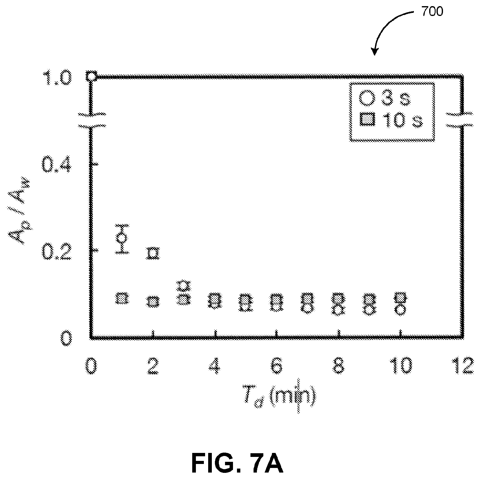
[0084] Referring to FIGS. 1A-C and 7A-E, the formation of the agglomerate 155 may be affected by varying the length of the exposure cycles T.sub.i, for example, between 3 seconds per minute and 10 seconds per minute, while the other parameters are held constant. For example, the angle of incidence .theta. may be fixed at 20.degree., the radial location x may be fixed at 5.0 millimeters, the input power E may be fixed at 3.0 watts, the duty ratio D may be fixed at 50%, the total exposure time T.sub.d may be fixed to 10 minutes, the length of the burst period T.sub.b may be fixed to 16 milliseconds, and the concentration N.sub.p may be fixed to 1.0.times.10.sup.4 particles per milliliter.
[0085] To further illustrate, FIG. 7A depicts a graph 700 illustrating the formation of the agglomerate 155 with different lengths exposure cycles T.sub.i, in accordance with some example embodiments. As shown in FIG. 7A, the formation of the agglomerate 155 may be quantified based on a ratio
A p A w , ##EQU00015##
wherein A.sub.p may correspond to a cross-sectional area occupied by the agglomerate 155 and A.sub.w may correspond to a cross-sectional area of the well 115. The graph 700 plots the different values of the ratio
A p A w ##EQU00016##
that are observed over the course of the total exposure time T.sub.d when the suspension 150 is subject to different lengths exposure cycles T.sub.i including, for example, 3 seconds per minute and 10 seconds per minute. FIGS. 7B-C depicts images of the agglomerate 155 formed at different lengths exposure cycles T.sub.i. For example, FIG. 7B depicts the agglomerate 155 that is formed when the suspension 150 is exposed to the acoustic streaming 162 for 3 seconds every minute while FIG. 7C depicts the agglomerate 150 that is formed when the suspension 150 is exposed to the acoustic streaming 162 for 10 seconds per minute. As shown in FIGS. 7A-C, the formation of the agglomerate 155 may be optimized when the suspension 150 is subject to shorter exposure cycles T.sub.i (e.g., T.sub.i=3 seconds per minute).
[0086] FIG. 8 depicts a flowchart illustrating a process 800 for acoustic wave based agglomeration, in accordance with some example embodiments. Referring to FIGS. 1-8, the process 700 may be performed by the apparatus 100.
[0087] At 802, one or more parameters for acoustic wave based agglomeration may be determined. In some example embodiments, the apparatus 100 may be configured to generate the acoustic waves 160, which may induce the acoustic streaming 162 within the suspension 150 and cause the formation of the agglomerate 155. As noted, the agglomerate 155 may be a three-dimensional formation of living cells. The parameters for generating the agglomerate 155 may include the angle of incidence .theta. of the acoustic waves 160, the radial location x of the acoustic streaming 162, the input power E applied to the acoustic wave device 110, the duty ratio D of the acoustic waves 160, the total exposure time T.sub.d to the acoustic waves 160, the length of a burst period T.sub.b of the acoustic waves 160, and/or the concentration N.sub.p of the solid particles within the suspension 150.
[0088] According to some example embodiments, the formation of the agglomerate 155 may be optimized when the angle of incident .theta. is between 5.degree. and 55.degree. from a bottom of the well 115, the radial location x is 1/2 to 3/4 of the distance between a center of the well 115 and an edge of the well 115, the input power E is intermittent at 50 milliwatts to 5.0 watts, the duty ratio D is between 10% and 50%, the length of the burst period T.sub.b is between 1 second to 100 seconds, the length of the burst cycle T.sub.i is between 0.1 seconds per minute to 15 seconds per minute, and the total exposure time T.sub.d is 1 cycle to 1000 cycles.
[0089] At 804, the apparatus 100 may form the agglomerate 155 by at least generating and delivering, in accordance with the one or more parameters, a plurality of acoustic waves to a well including a suspension containing a plurality of solid particles. For example, the acoustic wave device 110 may generate the plurality of acoustic waves 160, which may be delivered to the well 115 via the couplant material 140. The acoustic waves 160 may induce, within the suspension 150 held in the well 115, the acoustic streaming 162. The acoustic streaming 162 may generate the vortex 164, which may a shear-induced migration of the solid particles in the suspension 150. The agglomerate 155 may be formed when the vortex 164 cause at least a portion of the solid particles to concentrate toward a center of the well 115.
[0090] The subject matter described herein can be embodied in systems, apparatus, methods, and/or articles depending on the desired configuration. The implementations set forth in the foregoing description do not represent all implementations consistent with the subject matter described herein. Instead, they are merely some examples consistent with aspects related to the described subject matter. Although a few variations have been described in detail above, other modifications or additions are possible. In particular, further features and/or variations can be provided in addition to those set forth herein. For example, the implementations described above can be directed to various combinations and subcombinations of the disclosed features and/or combinations and subcombinations of several further features disclosed above. In addition, the logic flows depicted in the accompanying figures and/or described herein do not necessarily require the particular order shown, or sequential order, to achieve desirable results. Other implementations may be within the scope of the following claims.
* * * * *
D00000
D00001
D00002
D00003
D00004
D00005
D00006
D00007
D00008
D00009
D00010
D00011
D00012

D00013

D00014

D00015

D00016
D00017

D00018


XML
uspto.report is an independent third-party trademark research tool that is not affiliated, endorsed, or sponsored by the United States Patent and Trademark Office (USPTO) or any other governmental organization. The information provided by uspto.report is based on publicly available data at the time of writing and is intended for informational purposes only.
While we strive to provide accurate and up-to-date information, we do not guarantee the accuracy, completeness, reliability, or suitability of the information displayed on this site. The use of this site is at your own risk. Any reliance you place on such information is therefore strictly at your own risk.
All official trademark data, including owner information, should be verified by visiting the official USPTO website at www.uspto.gov. This site is not intended to replace professional legal advice and should not be used as a substitute for consulting with a legal professional who is knowledgeable about trademark law.