Elevator
HAKALA; Tero ; et al.
U.S. patent application number 16/532972 was filed with the patent office on 2019-11-28 for elevator. This patent application is currently assigned to KONE Corporation. The applicant listed for this patent is KONE Corporation. Invention is credited to Tero HAKALA, Ari KATTAINEN, Jussi LAHTEENMAKI, Jussi PERALA, Tero PUROSTO, Seppo SUUR-ASKOLA.
| Application Number | 20190359447 16/532972 |
| Document ID | / |
| Family ID | 58213029 |
| Filed Date | 2019-11-28 |


| United States Patent Application | 20190359447 |
| Kind Code | A1 |
| HAKALA; Tero ; et al. | November 28, 2019 |
ELEVATOR
Abstract
An elevator and a method for testing an operating condition of two or more elevator car brakes are provided, each of the car brakes including an actuator to control the car brake and each of the car brakes mounted to elevator car and fitted to selectively engage against a guide rail of an elevator car to stop movement of an elevator car or to open to enable movement of an elevator car. The method includes an empty car is kept at a standstill by providing a driving force upwards with all the N movers mounted to the elevator car, and total current Lot of all N movers is determined. One of the car brakes is applied while the others are kept open. The driving current of each of the movers is gradually decreased, and movement of elevator car is observed. When movement of elevator car is detected, the driving current at the moment movement started is recorded, and the recorded current is compared to a reference value, and if the recorded current is higher than the reference value, safety measures with the elevator are performed.
| Inventors: | HAKALA; Tero; (Helsinki, FI) ; KATTAINEN; Ari; (Helsinki, FI) ; LAHTEENMAKI; Jussi; (Helsinki, FI) ; SUUR-ASKOLA; Seppo; (Helsinki, FI) ; PERALA; Jussi; (Helsinki, FI) ; PUROSTO; Tero; (Helsinki, FI) | ||||||||||
| Applicant: |
|
||||||||||
|---|---|---|---|---|---|---|---|---|---|---|---|
| Assignee: | KONE Corporation Helsinki FI |
||||||||||
| Family ID: | 58213029 | ||||||||||
| Appl. No.: | 16/532972 | ||||||||||
| Filed: | August 6, 2019 |
Related U.S. Patent Documents
| Application Number | Filing Date | Patent Number | ||
|---|---|---|---|---|
| PCT/EP2018/054476 | Feb 23, 2018 | |||
| 16532972 | ||||
| Current U.S. Class: | 1/1 |
| Current CPC Class: | B66B 5/027 20130101; B66B 1/3492 20130101; B66B 2201/00 20130101; B66B 2201/34 20130101; B66B 1/36 20130101; H02P 3/08 20130101; B66B 5/0037 20130101; B66B 9/02 20130101; H02K 41/033 20130101; B66B 5/18 20130101; B66B 1/3453 20130101; H02P 25/064 20160201; B66B 11/0407 20130101; B66B 1/3476 20130101; B66B 5/0025 20130101; B66B 5/0031 20130101; B66B 5/16 20130101; B66B 5/0093 20130101; B66B 5/04 20130101; B66B 1/3461 20130101; B66B 9/003 20130101; B66B 2201/30 20130101; B66B 1/32 20130101; B66B 1/28 20130101; H02K 7/1023 20130101 |
| International Class: | B66B 1/32 20060101 B66B001/32; B66B 11/04 20060101 B66B011/04; B66B 1/36 20060101 B66B001/36; B66B 5/02 20060101 B66B005/02; B66B 5/18 20060101 B66B005/18; B66B 1/34 20060101 B66B001/34; B66B 5/00 20060101 B66B005/00; H02K 41/03 20060101 H02K041/03 |
Foreign Application Data
| Date | Code | Application Number |
|---|---|---|
| Mar 2, 2017 | EP | 17158966.6 |
Claims
1. An elevator comprising: an elevator car; one or more guide rails to define path of movement of an elevator car; and an electric linear motor comprising at least one linear stator designed to be located in a fixed correlation to an environment, and at least one mover designed for connection with an elevator car to be moved and co-acting with the stator to move the car, the electric linear motor comprising a stator beam supporting said at least one stator, the stator beam having at least one side face carrying ferromagnetic teeth of said stator spaced apart by a pitch, and the mover comprises at least one counter-face facing said side face of the stator beam, the motor further comprising electro-magnetic components being mounted to the mover and/or to the stator to provide propulsion force to the elevator car; elevator two or more elevator car brakes mounted to an elevator car, each of the car brakes comprising an actuator to control the car brake and each of the car brakes being fitted to selectively engage against a guide rail of an elevator car to stop movement of an elevator car or to open to enable movement of an elevator car.
2. The elevator according to claim 1, further comprising a backup-power supply and an emergency stop circuit, the emergency stop circuit being connected to a position and/or velocity and/or acceleration sensor of the elevator, and the emergency stop circuit being configured to adjust the energization of the electromagnetic components and/or the actuators of one or more car brakes depending on the signal of the above sensor.
3. The elevator according to claim 2, wherein the backup-power supply is a battery.
4. The elevator according to claim 3, further comprising a battery monitoring circuit for monitoring the functional status of the battery.
5. The elevator according to claim 2, wherein the emergency stop circuit is configured to adjust the energization of the electromagnetic components and/or the actuators of one or more car brakes such that the car stops within a defined stopping distance.
6. The elevator according to claim 1, wherein the elevator control comprises a brake test circuit configured to operate in a brake test mode wherein only one actuator is de-energized to apply elevator car brake when the car is not moving.
7. The elevator according to claim 1, wherein associated with each car brake there is a load sensor, arranged between the car and the car brake to measure a total weight of car.
8. A method for testing an operating condition of an elevator car brake in the elevator according to claim 1, the method comprising the succession of following steps: keeping an empty car at a standstill by providing a driving force upwards with the at least one mover mounted to the elevator car; applying one of the car brakes while the others are kept open; gradually decreasing the driving current of the at least one mover and observing movement of elevator car; when movement of elevator car is detected, recording the driving current of the at least one mover at the moment movement started, and comparing the recorded current to a reference value; and if the recorded current is higher than the reference value, performing safety measures with the elevator.
9. A method for testing an operating condition of elevator car brake in an elevator according to claim 1, wherein associated with each of the car brakes there is a load sensor, arranged between the car and the car brake to measure a total weight of car, the method comprising the succession of following steps: applying one of the car brakes while the others are kept open; keeping an empty car at a standstill by providing a driving force upwards with the at least one mover, such that the load sensor of the applied car brake indicates zero weight; gradually decreasing the driving current of the at least one mover, and observing movement of elevator car; when movement of elevator car is detected, recording the reading of the load sensor of the applied car brake at the moment movement started, and comparing the recorded reading to a reference value; and if the recorded reading of the load sensor is lower than the reference value, performing safety measures with the elevator.
10. The method according to claim 8, which wherein the brake test mode is performed when the car is stopping at a floor.
11. The method according to claim 8, wherein the safety measures comprise at least one of the following steps: sending a log report with the energization when the car starts moving to a maintenance center; sending a log report with the threshold value which the energization was compared to a maintenance center; putting the elevator out of service; and issuing a maintenance request.
12. The elevator according to claim 3, wherein the emergency stop circuit is configured to adjust the energization of the electromagnetic components and/or the actuators of one or more car brakes such that the car stops within a defined stopping distance.
13. The elevator according to claim 4, wherein the emergency stop circuit is configured to adjust the energization of the electromagnetic components and/or the actuators of one or more car brakes such that the car stops within a defined stopping distance.
14. The elevator according to claim 2, wherein the elevator control comprises a brake test circuit configured to operate in a brake test mode wherein only one actuator is de-energized to apply elevator car brake when the car is not moving.
15. The elevator according to claim 3, wherein the elevator control comprises a brake test circuit configured to operate in a brake test mode wherein only one actuator is de-energized to apply elevator car brake when the car is not moving.
16. The elevator according to claim 4, wherein the elevator control comprises a brake test circuit configured to operate in a brake test mode wherein only one actuator is de-energized to apply elevator car brake when the car is not moving.
17. The elevator according to claim 5, wherein the elevator control comprises a brake test circuit configured to operate in a brake test mode wherein only one actuator is de-energized to apply elevator car brake when the car is not moving.
18. The elevator according to claim 2, wherein associated with each car brake there is a load sensor, arranged between the car and the car brake to measure total weight of car.
19. The elevator according to claim 3, wherein associated with each car brake there is a load sensor, arranged between the car and the car brake to measure total weight of car.
20. The elevator according to claim 4, wherein associated with each car brake there is a load sensor, arranged between the car and the car brake to measure total weight of car.
Description
[0001] The present invention relates to an elevator comprising two or more car brakes to brake elevator car movement or to hold elevator car at standstill. The elevator may comprise an electric linear motor as it is disclosed in the WO 2016/207136 A1. The linear motor may comprise a linear stator designed to be located in a fixed correlation to an environment, particularly a building. The elevator may further comprise at least one mover designed for connection with an elevator car to be moved and co-acting with the stator to move the car. The motor may comprise a stator beam supporting said at least one stator, which stator beam has at least one side face carrying ferromagnetic poles of said stator spaced apart by a pitch. Accordingly, the mover may comprise at least one counter-face facing said side face of the stator beam, in which counter-face electromagnetic components of the mover are arranged to co-act with the ferromagnetic poles of the stator beam. During the operation of the elevator, particularly when the elevator car is running, the magnetic field of the electromagnetic components of the mover keep the counter-face of the mover spaced apart from the side face of the stator by an air gap a. This new technology has proved to be quite efficient, particularly in elevator constructions in which the travelling of the car is not only vertical. For this reason, the general design of elevator brakes which were always based on the braking of the traction sheave driving an elevator car via the hoisting ropes is not applicable in this concept. Furthermore, if hoisting ropes are very long, as is the case with high-rise elevators, movement of the elevator car due to sway or stretch of the hoisting ropes may cause unwanted movement of elevator car. For these reasons, among others, car brakes have been provided in connection with elevator car. By engaging the car brakes against guide rails, elevator car can be hold standstill or movement of elevator car can be braked.
[0002] To improve elevator safety, this invention suggests a method for monitoring operating condition of the car brakes. The object is solved with an elevator according to claim 1 as well as with methods according to claims 8 and 9. Advantageous embodiments of the invention are subject matter of the corresponding dependent claims. Preferred embodiments of the invention are also subject matter of the description and of the drawings.
[0003] A first aspect of the invention is an elevator comprising an elevator car and one or more guide rails to define path of movement of an elevator car, the elevator further comprising an electric linear motor comprising at least one linear stator designed to be located in a fixed correlation to an environment, particularly building, and at least one mover designed for connection with an elevator car to be moved and co-acting with the stator to move the car. Motor comprises a stator beam supporting said at least one stator, which stator beam has at least one side face carrying ferromagnetic teeth of said stator spaced apart by a pitch, and which mover comprises at least one counter-face facing said side face(s) of the stator beam, the motor further comprising electro-magnetic components being mounted to the mover and/or to the stator to provide propulsion force to the elevator car, wherein the elevator comprises two or more elevator car brakes mounted to an elevator car, each of the car brakes comprising an actuator to control the car brake and each of the car brakes fitted to selectively engage against a guide rail of an elevator car to stop movement of an elevator car or to open to enable movement of an elevator car. One suitable car brake is represented in EP 0856485 A1. It has as an actuator an electromagnet 15 with coil 16 and magnetic core to control opening/engaging of the brake against guide rail 2. When the car brake is engaged, elevator car is kept at its level via mere friction of braking surfaces of the car brake against the guide rail.
[0004] According to an embodiment, the elevator comprises a backup-power supply and an emergency stop circuit, which emergency stop circuit is connected to a position and/or velocity and/or acceleration sensor of the elevator, and which emergency stop circuit is configured to adjust the energization of the electromagnetic components of the linear motor and/or the actuators of one or more car brakes depending on the signal of the above sensor(s). Via this means it can be ensured that in any case of power off, the elevator does not suddenly stop but via the backup power supply, the emergency stop circuit ensures deceleration of the elevator car within allowed tolerances until the stop of the elevator car. This measure ensures the safety of the passengers in any case of power failure of the AC mains.
[0005] According to an embodiment, the emergency stop circuit is configured to adjust the energization of the electromagnetic components and/or the actuators of one or more car brakes such that the car stops within a defined stopping distance.
[0006] According to an embodiment, the elevator control comprises a brake test circuit configured to operate in a brake test mode wherein only one actuator is de-energized to apply elevator car brake when the car is not moving, particularly if it is stopping at a floor.
[0007] According to an embodiment, associated with each car brake there is a load sensor, such as a strain gauge, arranged between the car and the car brake to measure total weight of car.
[0008] Second aspect of the invention is a method for testing operating condition of an elevator car brake in an elevator according to the first aspect of the invention. The method comprises the succession of following steps: an empty car is kept standstill by providing a driving force upwards with the at least one mover mounted to the elevator car. One of the car brakes is applied while the others are kept open. The driving current of the at least one mover is gradually decreased, and movement of elevator car is observed. When movement of elevator car is detected, the total driving current of the at least one mover at the moment movement started is recorded, and the recorded current is compared to a reference value. If the recorded current is higher than the reference value, safety measures with the elevator are performed. Applying of the car brake means that, by controlling the actuator, brake is engaged against the guide rail to brake movement of the car/hold the car at level.
[0009] A third aspect of the invention is a method for testing operating condition of an elevator car brake in an elevator according to the first aspect of the invention, wherein the elevator further comprises associated with each of the car brakes a load sensor, such as a strain gauge, which is arranged between the car and the car brake to measure total weight of car, the method comprising the succession of following steps: one of the car brakes is applied while the others are kept open, and an empty car is kept standstill by providing a driving force upwards with the at least one mover, such that the load sensor of the applied car brake indicates preferably zero weight. The driving current of the at least one mover is gradually decreased, and movement of elevator car is observed, and when movement of elevator car is detected, the reading of the load sensor of the applied car brake at the moment movement started is recorded, and the recorded reading is compared to a reference value. If the recorded reading of the load sensor is lower than the reference value, safety measures with the elevator are performed. According to a refinement, as the driving current of the at least one mover is gradually decreased, at the same time the reading of the load sensor of the engaged car brake is observed and compared to said driving current, to ensure that decreasing of the driving current causes reading of the load sensor to increase with a predefined pattern. This means that correct operation of the load sensor can be monitored.
[0010] The car brakes are preferably tested one at a time, such that after one car brake has been tested, it is opened and another one is applied and then the testing method according to the second or third aspect of the invention is repeated.
[0011] According to an embodiment, brake test mode is performed when the car is stopping at a floor.
[0012] According to an embodiment, the safety measures comprises at least one of the following steps: sending a log report with the energization when the car starts moving to a maintenance center, sending a log report with the threshold value which the energization was compared to a maintenance center, putting the elevator out of service, issuing a maintenance request
[0013] Preferably, this backup-power supply is a battery, but it also may be a series of super-capacitors and/or second independent power supply network.
[0014] In case a battery is used as a backup-power supply, the elevator preferably comprises a battery monitoring circuit for monitoring the function or status of the battery. By this means it can be ensured that the functional status of the battery is such that the elevator stop circuit is always able to ensure a smooth elevator stop drive in case of power off as mentioned above.
[0015] Preferably, on this behalf, the current of the movers is compared with at least one threshold value, which allows the differentiation of brake in order/brake has to be maintained or is not working in a sufficient manner to provided required safety. Preferably two threshold values are provided for comparison with the critical current value, so that three different operational status of the brake can be identified: brake in order, brake needs maintenance and brake is not safe as mentioned above in connection with the description of the inventive elevator.
[0016] Preferably, the upwards propulsion force of each mover is adjusted to a value corresponding to a test force F defined as follows:
F=(M+L)g/(N-1)
[0017] wherein
[0018] F is required test force for testing one brake at a time
[0019] M is weight of empty elevator car in kilograms
[0020] L is rated maximum load of elevator car in kilograms
[0021] g is gravity constant 9.81
[0022] N is number of brakes in one car.
[0023] Example: N=4 brakes, M=800 Kg, L=1000 Kg, then
F=1800 Kg*9.81/3=5886 N.
[0024] This also fulfils the requirement that all N brakes must hold together (125%*L+M)g In the above example the requirement is: (125%*1000 Kg+800 Kg)9.81=20110 N. On the other hand it has already been tested that 4 brakes can perform: 4*5886 N=23544 N which is sufficient.
[0025] If this test force does not lead to the car starts moving, the brake test is terminated and the brake is evaluated as being in order.
[0026] In some embodiments, it may be also necessary to not only decrease the upwards propulsion force during testing but also to further increase it in the opposite direction, e.g. in the downwards direction or otherwise in the direction of interaction of gravity, to increase the test force to a magnitude required for testing.
[0027] It is clear for the skilled person that the above-mentioned embodiments can be combined with each other arbitrarily. It has been mentioned that preferably an elevator car is supported with two stator beams and two vertically spaced apart movers which means four movers per elevator car. Preferably the elevator car is supported by at least two car brakes, most preferably by at least 4 car brakes. This number of movers/car brakes per elevator car may differ from this value. If the stator beam is large enough as well as the mover is large and long enough, even one stator beam and one mover per elevator car may be sufficient to support the car and to implement the necessary brake interface. If there are only two car brakes per elevator car, they are preferably associated with separate guide rails to enhance reliability and safety.
[0028] Following terms are used as synonyms: critical energization value--energization value when the car starts moving in the brake test mode; elevator control--elevator motor control; car--elevator car; brake interface--elevator brake
[0029] The invention is hereinafter described via an example with the aid of the enclosed drawings.
BRIEF DESCRIPTION OF THE DRAWINGS
[0030] The invention is now described hereinafter with respect to the enclosed drawing. In this drawing
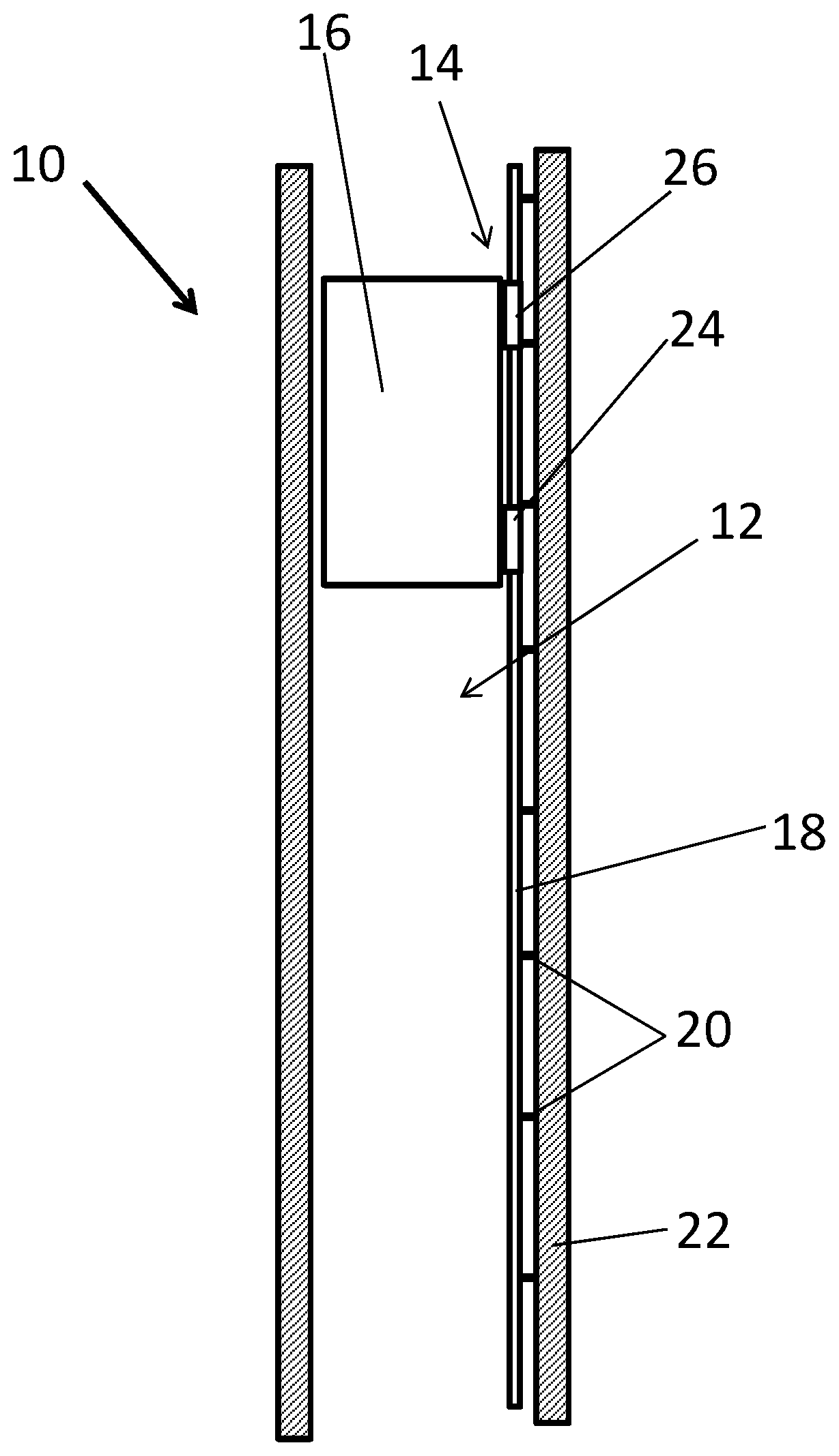
[0031] FIG. 1 shows a side view of an elevator shaft with a linear elevator motor according to the invention comprising two parallel stator beams,
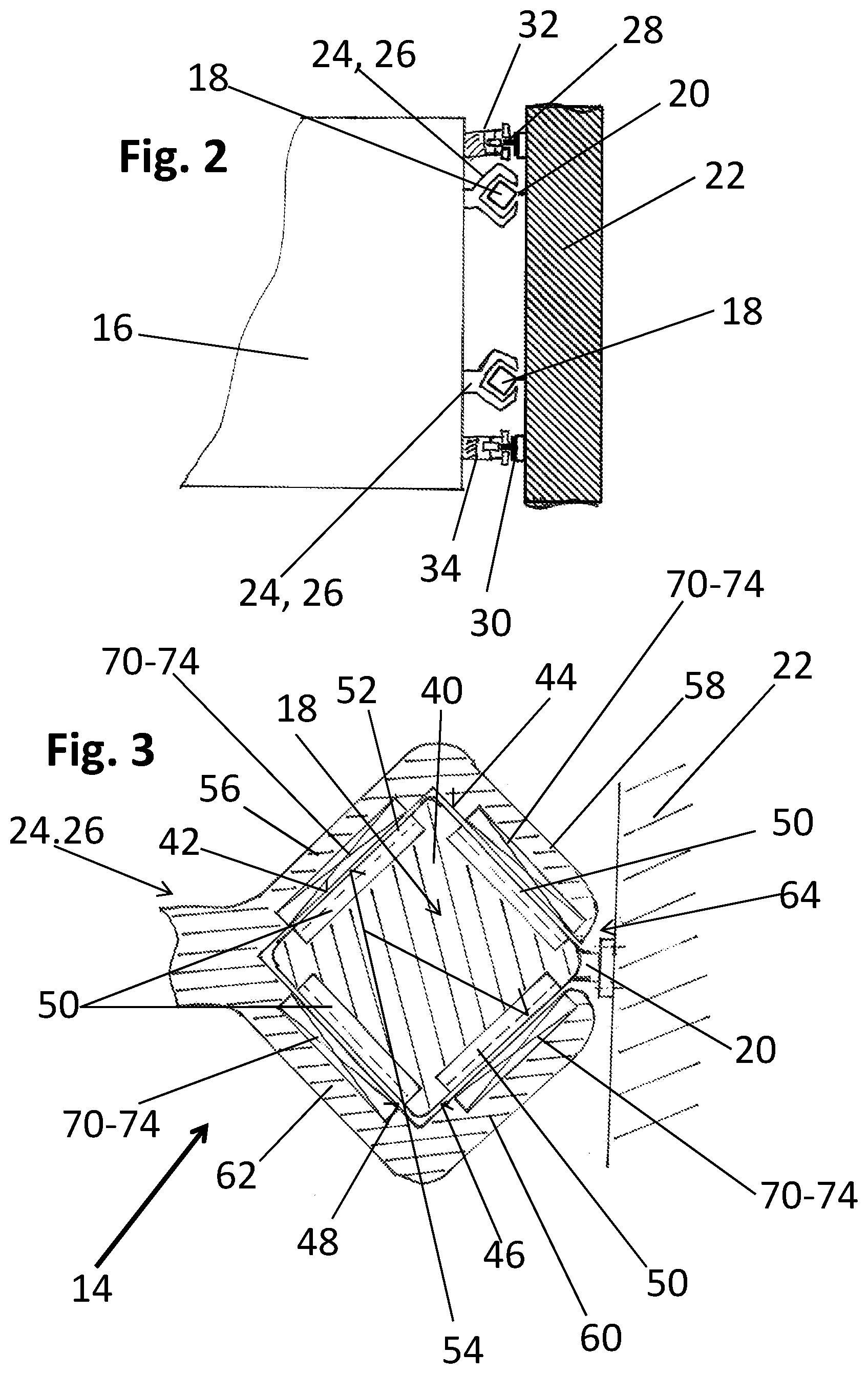
[0032] FIG. 2 shows a horizontal cross-section of the parts of the elevator motor and the guide rails in the area between the elevator car and the shaft wall of FIG. 1,
[0033] FIG. 3 shows a cross-section through a stator beam and a mover of FIG. 2,
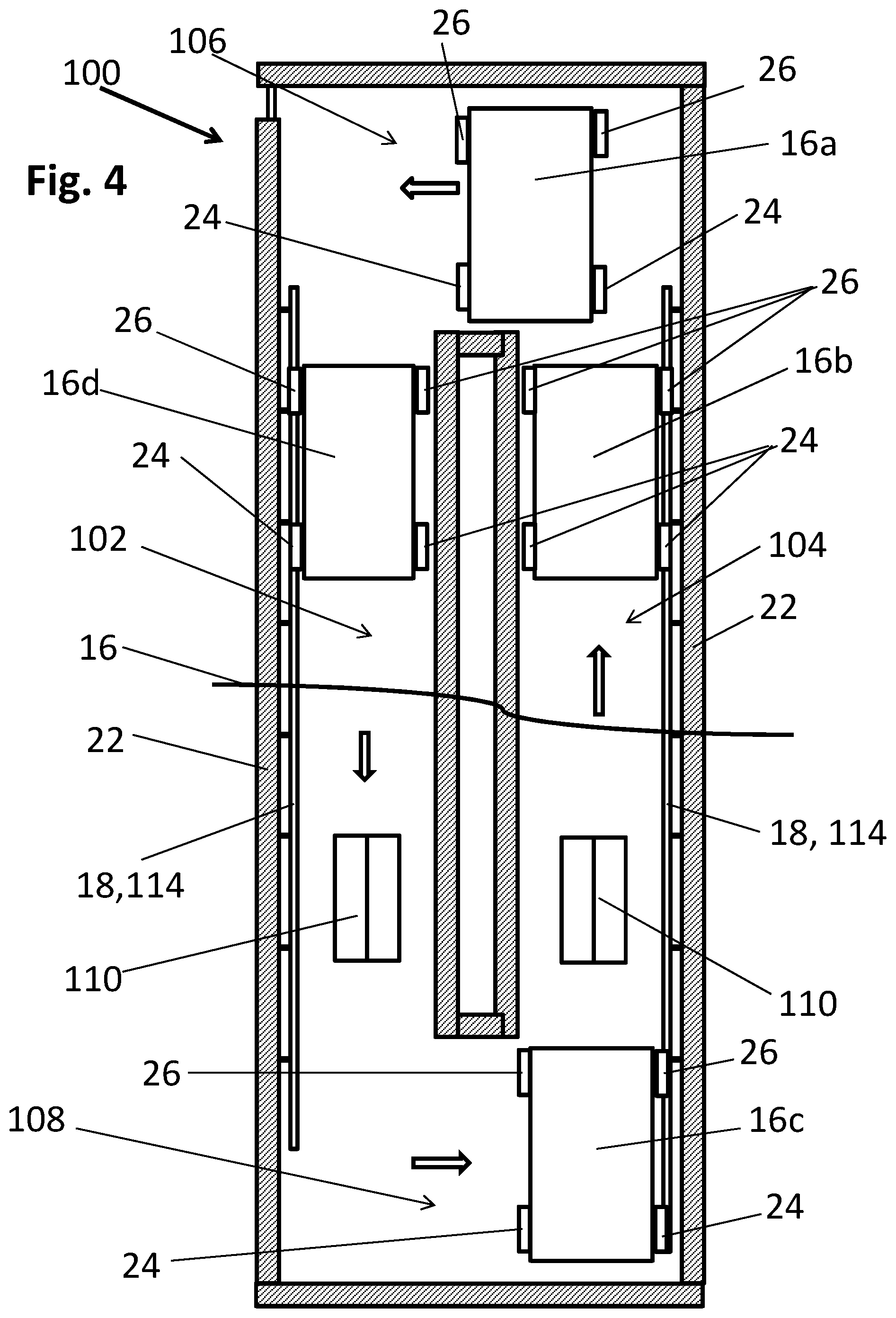
[0034] FIG. 4 shows a side view of an elevator having two elevator shafts which are connected at their upper and lower ends with horizontal passages,
[0035] FIG. 5 shows a horizontal cross-section of the connecting part between the shaft wall and an elevator car at the car guide position, showing a guide element of the elevator car with two pivoted guide rollers which guide element is running along guide surfaces of the stator beam of FIG. 7,
[0036] FIG. 6 shows a schematic side view of an elevator system having two elevator shafts which are connected with horizontal passages at each elevator floor whereby the landing doors are located in the area of the horizontal passages between each shaft,
[0037] FIG. 7 shows a horizontal moving mechanism with shaft-side horizontal guide tracks and a car-side horizontal moving means comprising rollers co-acting with the horizontal guide tracks,
[0038] FIG. 8 shows a schematic view of the elevator control controlling movers in a brake test mode,
[0039] FIG. 9 shows a diagram regarding the use of the critical energization for deriving brake status information/perform failure measures.
DESCRIPTION OF THE PREFERRED EMBODIMENTS
[0040] It is emphasized that identical parts or parts with the same functionality are designated by the same reference numbers in all figures.
[0041] FIG. 1 shows an elevator 10 comprising an elevator shaft 12 wherein an elevator car 16 moves up and down as an element to be moved, along a path of movement defined by two guide rails. The elevator 10 has a linear elevator motor 14. The linear elevator motor 14 comprises stators 50 (see FIG. 3) located in a side face of a stator beam 18 which is mounted with fastening elements 20 to a shaft wall 22 of the elevator shaft 12. In this example the elevator 10 has two parallel stator beams 18, which can be seen in FIG. 2.
[0042] The elevator car 16 comprises two movers 24, 26 located one above the other. The lower mover 24 is located in the lower half of the elevator car whereas the upper mover 26 is located in the upper half of the elevator car. These two movers 24, 26 comprise electro-magnetic components as e.g. irons, windings and permanent magnets 70, 71, 72, 74, 76 (FIG. 4) which co-act with stator poles 52 located in the side faces of the stator beam 18, formed by stator teeth. Accordingly, the elevator car travels upwards and downwards via corresponding control of both movers 24, 26 co-acting with the stator beams 18.
[0043] Of course, the elevator car has a corresponding set of two movers 24, 26 for each vertical stator beam 18 so that the elevator car 16 has in total four movers, two lower movers 24 and two upper movers 26 to co-act with two stator beams 18.
[0044] Of course, each stator beam 18 may have one or several stators 50 as it is shown in FIGS. 2 and 3.
[0045] In some other embodiments, the windings may be provided in the stator and mover has permanents magnets. In this case, the propulsion force for the movers is provided by supplying current to the stator coils.
[0046] FIG. 2 shows in one embodiment car guides 32, 34 of the elevator car 16 co-acting with guide rails 28 running vertically along the shaft wall 22 of FIG. 1. The shaft wall 22 comprises two parallel guide rails 28, 30 co-acting with corresponding car guides 32, 34. Each car guide 32, 34 has a set of guide rollers co-acting with the car guide rails 28, 30. As these car guides 32, 34 in connection with the car guide rails 28, 30 are configured for a rucksack type suspension, the corresponding guide system 28, 30, 32, 34 is configured to keep the car 16 horizontally in connection with the shaft wall 22 as these both car guide rails 28, 30 are the only guide rails of the elevator car 16 in the shaft 12. In connection with each elevator car there are four car brakes as well as for movers. Two of the car brakes are fitted to engage same guide rail (car brakes , which are not shown in FIG. 2, are the same type as disclosed in EP 0856485 A1).
[0047] The vertical stator beams 18 as well as the movers 24, 26 of the elevator car 16 are shown in more detail in FIG. 3. Generally, guide rails with a round cross-section may be used which are surrounded by rollers of the car guide, thereby fixing the car horizontally in connection with the guide rail.
[0048] According to FIG. 3 the vertical stator beam 18 comprises a metal support structure 40 with a square cross-section. On each side the support structure 40 carries a metal stator rod 50 comprising stator teeth 52, which form the four side faces 42, 44, 46, 48 of the stator beam 18. Each of these stator rods (or bars) 50 with the stator teeth 52 forms a stator of the linear motor 14 so that the stator beam 18 shown in FIG. 3 comprises four stators. The stator teeth 52 co-act with windings 74, 76 (FIG. 4) and mover irons 70,72 and permanent magnets 71 located along counter-faces 54 in the four arms 56, 58, 60, 62 of the C-type profile of the mover 24, 26. This C-type profile of the mover surrounds the stator beam 18 but leaves an opening 64 for the adaption of the fastening elements 20, as the mover 24, 26 travels along the shaft 12.
[0049] The stator rods 50 on all four side faces 42, 44, 46, 48 have the same pitch d. Anyway, the first and third side face 42, 46 of the stator beam also have an identical teeth position in vertical direction whereas the second and fourth side face 44, 48 have the same pitch but the teeth position is vertically offset with respect to the stator teeth 52 on the first and third side face 42, 46 by a 1/4 pitch.
[0050] Via this arrangement, it is ensured that on one hand, the horizontal forces between the stators 50 on opposite sides eliminate each other whereas the vertical offset of the pitches of the side faces oriented rectangular leads to a better efficiency and a smoother run of the elevator motor, as a moving step of such a motor 14 is a half pitch. By the fact that four stators 50 are located within the stator beam 18 the force generated between the movers 24, 26 and the stator beam 18 is multiplied by four, thereby achieving less horizontal ripples and a smoother movement of the movers 24, 26 with respect to the vertical stator beam 18.
[0051] FIG. 4 shows an elevator 100 having two elevator shafts 102, 104 which are connected by an upper horizontal passage 106 at the top end of both shafts 102, 104 as well as a lower horizontal passage 108 at the bottom end of both elevator shafts 102, 104. Thus, the both elevator shafts 102, 104 with the upper and lower horizontal passage 106, 108 form a closed loop whereby the movement of the elevator cars 16a-16d is only allowed in one direction according to the arrows shown in the figure. By this measure it is ensured that cars run only in one direction in each of the shafts which lead to a higher transport capacity and to an easier control of the cars in the shaft.
[0052] In both elevator shafts 102, 104, vertical stator beams 18, 114 e.g. according to one of the previous embodiments, or according to FIGS. 4 are located which co-act with movers 24, 26 located at the elevator cars 16a-16d. Each shaft 102, 104 may comprise preferably two, three or four parallel stator beams 18, 114. The figure shows landing doors 110 located in the first elevator shaft 102 as well as in the second elevator shaft 104. The cars 16a-16d are horizontally moved in the horizontal passages 106, 108 in a not specified manner by horizontal moving mechanisms.
[0053] Both elevator shafts are cut out along the cutting line 112 for clarity reasons, as normally this concept is preferably designed for high-rise elevators having 20 floors or more. Accordingly, the two shafts 102, 104 are able to accommodate a much larger number of elevator cars than the four cars 16a-16d shown in the figure. Each car 16a-16d is able to move largely independent of the others within the two shafts 102, 104 except the fact that collisions between cars have to be avoided. By the fact that in the first elevator shaft 102 the elevator cars 16a-16d only drive downwards and in the second elevator shaft 104 only drive upwards, the probability of mutual affection is decreased. Furthermore, by this circular moving scheme, the transport capacity of both shafts is drastically increased on one hand because now the two elevator shafts may comprise much more elevator cars than in conventional systems and on the other hand, because in each elevator shaft, all elevator cars only move in the same direction, avoiding counter-movements of cars which reduce an economic shaft use and necessitate extensive anti-collision control.
[0054] FIG. 6 shows an elevator 200 comprising two elevator shafts 202, 204 which are preferably no longer separated by shaft walls. The vertical stator beams 114 correspond to the stator beams shown in FIG. 5 and the car guides 140 of the cars 16a-16d of FIG. 6 correspond to the car guides 140 shown in FIG. 5. In FIG. 6, at each elevator floor, horizontal guide tracks (see also FIG. 6) 206 are extending horizontally along horizontal passages 208 located between the two elevator shafts 202, 204 whereby the term "elevator shaft" in this connection designates the vertical moving paths of the elevator cars 16a-16d in this elevator 200. The two remaining shaft walls 22 which are opposite to the horizontal passages 208 do not only comprise the vertical stator beams but also the vertical bus bars which are not shown for clarity reasons, as FIG. 6 focuses on the horizontal moving mechanism 205. The horizontal moving mechanism 205 comprises the horizontal guide tracks 206 on each elevator floor and a horizontal moving means 210 located on top of each elevator car 16a-16d. The horizontal moving means 210 of the elevator car comprises support rollers 212 which can be moved between a retracted position and an operational position wherein the support rollers 212 run on the horizontal guide tracks 206.
[0055] The moving pattern of the elevator cars in the elevator car 200 corresponds to that of FIG. 4 which means that in the first elevator shaft 202, the elevators all move in the same direction, i.e. upwards, whereas in the second elevator shaft 204 all elevator cars 16a-16d move downwards. Therefore, also in this elevator 200, a kind of circular movement is achieved whereby the circular movement can be shortened as the elevator cars can travel from one elevator shaft 202, 204 into the other at each elevator floor via the horizontal moving mechanism 205 comprising the horizontal guide tracks 206 and the horizontal moving means 210 of the elevator car.
[0056] The function of the horizontal moving mechanism 205 based on the interaction between the horizontal guide tracks 206 and the horizontal moving means 210 of the elevator car 16a-16d is described in more detail with respect to FIG. 7. The elevator car 16a-16d comprises a car control 214 having a wireless transmission means 216 for wireless communication with the elevator control. Furthermore, the elevator car 16a-16d comprises a power source 218, preferably an accumulator, which feeds the movers 24, 26; 126 of the elevator car 16, 16a-16d as well as all other electrical components connected to the elevator car. The horizontal moving means 210 comprises of four roller arrangements 220. Each roller arrangement 220 comprises a mounting base 222 on which a support arm 224 is pivotally hinged. The support arm 224 can be moved between a retracted position (shown on the left side of the figure) and an operational position (shown on the right side) in which the support roller 212 runs on top of the horizontal guide track 206. Connected with the support arm 224 is a drive member 226 on which the support roller is supported. The drive member comprises an electric motor which is configured to rotate the support roller 212 on the horizontal guide track 206. It is self-evident that any operation of the pivot mechanism in the mounting base 222 can be prohibited when the support roller is currently positioned in the retracted position shown on the left side as well as in the operational position of the support roller 212 on the horizontal guide track 206. Therefore a locking mechanism (not shown) is preferably provided to lock the corresponding positions.
[0057] FIG. 8 shows an embodiment of the invention with an elevator (motor) control 230, preferably comprising an emergency stop circuit 232 backed-up by an backup power supply 234, preferably a battery.
[0058] The elevator control 230 selectively energizes the coils of the car brakes 301, 302 to open or apply the car brakes. When applied, the car brakes 301, 302 engage against guide rails (not shown in FIG. 8). The elevator control 230 also energizes the windings 74, 76 of the movers 24, 26 on one hand as to regulate the air gap between stator side faces 42-48 and counterfaces 54 of the mover 24, 26. On the other hand the elevator control energizes the windings 74, 76 as to move the car along the stator beams 18.
[0059] Before the car begins to move the elevator control 230 energizes the windings 74, 76 as to regulate the air gap and only afterwards starts to energize the windings in a way as to move the car. In contrast when the car shall stop at a floor or in emergency cases the car brakes 301, 302 are applied as to decelerate the car 16 to stop and hold the car at standstill.
[0060] The elevator control 230 comprises a braking test circuit 236 which in a braking test mode (when the car brakes 301, 302 are applied (car is stopped) and the brake interface is active) energizes the movers, and opens only one car brake such that the other car brake is still engaged. Via decreasing upwards propulsion force of the movers 24 the force acting on the engaged car brake increases due to gravity until the engaged car brake is no longer able to withstand the force, which is when the car starts moving.
[0061] The emergency stop circuit 232 of the elevator control ensures safe deceleration and stop of the elevator car in all abnormal operation conditions of the elevator, particularly in case of an AC power failure. In this case the elevator control immediately switches the power supply for the mover windings 74, 76 to the backup power supply 234 and continues current supply to magnetizing coils of the car brakes from the backup power supply. Thereby the elevator control 230 decelerates the car to stop either with a defined deceleration and/or within a defined stopping distance. After car stop the mover windings 74, 76 are de-energized and car brakes 301, 302 are applied so that the car 16 is safely supported on the stator beams 18. Preferably the car might be driven in an emergency car ride to the next floor in driving direction so that the passengers may leave the car. This option is only provided for emergency situations in which the elevator car is allowed to drive to the next floor, e.g. in case of a power failure of AC mains.
[0062] Optionally the elevator control 230 may comprise a battery monitoring circuit 238 for the backup power supply 234 to ensure functionality of the backup power supply in emergency situations. This battery monitoring circuit may issue a battery change signal if the battery performance decreases.
[0063] FIG. 9 show a schematic diagram of the checking of the functional state of the car brake, formed by the brake interface 51, 55.
[0064] At the start 240 of the brake test mode the brake test circuit 236 applies one of the car brakes while the other ones remain open. Upwards propulsion force is provided by supplying current to the windings of the movers 24. In step 242 the current flow of the windings 74, 76 generating upwards propulsion force is decreased.
[0065] In the first deciding step 244 it is checked whether the elevator car starts moving which information is obtained via position sensors and/or velocity sensors and/or acceleration sensors of the elevator. If the elevator does not start moving the process loops back to step 242 wherein the current flow generating upwards propulsion force is further decreased. If the elevator starts moving the first deciding step 244 branches to log step 246 wherein the critical current flow when the car began moving is recorded. In the second deciding step 248 the critical current flow is compared with a first threshold value. If the critical current flow is below this first threshold value the process moves to the third deciding step 252. If the critical current flow value is above the first threshold value the elevator is taken out of service in step 250 and a notice is given to a remote maintenance center, possibly comprising the critical current flow value and optionally the first threshold value.
[0066] In the third deciding step 252 the critical current flow value is compared with a second threshold value which is lower than the first threshold value. When the critical current flow (current) is above the second threshold value a maintenance signal is issued to a remote maintenance center in step 254. This signal may comprise information about the critical current flow value as well as about one or both threshold values.
[0067] The braking mode is stopped in termination step 256 whereafter the normal operating mode of the elevator is started.
[0068] It is clear for the skilled person that the retracted and operational position of the support roller 212 is controlled in synchronization with the initiation and releasing of the contact between the movers 126 and the corresponding vertical stator beams 114. Via this arrangement, it is ensured that the car is always supported in vertical direction either by the force of the mover 126 on the vertical stator beam 114 or by the support of the support rollers 212 on the horizontal guide tracks 206.
[0069] Thus, high safety of the elevator car may be maintained corresponding to a gripping device.
[0070] The invention can be carried out within the scope of the appended patent claims. Thus, the above-mentioned embodiments should not be understood as delimiting the invention.
LIST OF REFERENCE NUMBERS
[0071] 10 elevator [0072] 12 elevator shaft [0073] 14 elevator motor [0074] 16 elevator car [0075] 18 stator beam [0076] 20 fastening elements [0077] 22 shaft wall/shaft side [0078] 24 lower mover [0079] 26 upper mover [0080] 28 first guide rail [0081] 30 second guide rail [0082] 32 first car guide [0083] 34 second car guide [0084] 40 support structure [0085] 42 first side face [0086] 44 second side face [0087] 50 stator/stator rod [0088] 51 stator brake surface-stator braking pad [0089] 52 stator teeth [0090] 53 teeth gaps [0091] 54 counter face of mover [0092] 55 mover brake surface--mover braking pad [0093] 56 first arm of C-profile mover [0094] 58 second arm of C-profile mover [0095] 60 third arm of C-profile mover [0096] 62 fourth arm of C-profile mover [0097] 70 first mover iron [0098] 71 permanent magnet [0099] 72 second mover iron [0100] 74 first winding [0101] 76 second winding [0102] 100 elevator (second embodiment) [0103] 102 first elevator shaft [0104] 104 second elevator shaft [0105] 106 upper horizontal passage [0106] 108 lower horizontal passage [0107] 110 landing door [0108] 114 stator beam (second embodiment) [0109] 116 first side face (first guide face) [0110] 118 second side face [0111] 120 third side face [0112] 122 fourth side face (second guide face) [0113] 124 fifth side face (third guide face) [0114] 126 mover (second embodiment) [0115] 128 mounting element [0116] 130 bus bar [0117] 132 connector rails [0118] 134 contactor [0119] 136 spring support [0120] 140 car guide (second embodiment) [0121] 142 first guide roller, at the car side [0122] 144 second guide roller, at the shaft wall side [0123] 146 third guide roller, at the shaft wall side [0124] 148 pivot arm [0125] 150 pivoting mechanism [0126] 200 elevator (third embodiment) [0127] 202 first elevator shaft [0128] 204 second elevator shaft [0129] 205 horizontal moving mechanism [0130] 206 horizontal guide track [0131] 208 horizontal passage [0132] 210 horizontal moving means mounted to the elevator car [0133] 212 support roller [0134] 214 car control [0135] 216 wireless transmission means [0136] 218 power supply [0137] 220 roller arrangement [0138] 222 mounting base [0139] 224 support arm [0140] 226 drive member [0141] 230 elevator control [0142] 232 emergency stop circuit [0143] 234 backup power supply [0144] 236 brake test circuit [0145] 238 battery monitoring circuit [0146] 240 start of brake test mode--a part of the movers is energized, a part is de-energized [0147] 242 increasing the energization/current of the energized mover [0148] 244 first deciding step--car starts moving? [0149] 246 recording the critical energization/current [0150] 248 second deciding step--first threshold value passed by critical energization value? [0151] 250 elevator taken out of service [0152] 252 third deciding step--second threshold value passed by critical energization value? [0153] 254 maintenance requested for the elevator [0154] 256 end of the brake test mode
* * * * *
D00000
D00001
D00002
D00003
D00004
D00005
D00006
D00007
XML
uspto.report is an independent third-party trademark research tool that is not affiliated, endorsed, or sponsored by the United States Patent and Trademark Office (USPTO) or any other governmental organization. The information provided by uspto.report is based on publicly available data at the time of writing and is intended for informational purposes only.
While we strive to provide accurate and up-to-date information, we do not guarantee the accuracy, completeness, reliability, or suitability of the information displayed on this site. The use of this site is at your own risk. Any reliance you place on such information is therefore strictly at your own risk.
All official trademark data, including owner information, should be verified by visiting the official USPTO website at www.uspto.gov. This site is not intended to replace professional legal advice and should not be used as a substitute for consulting with a legal professional who is knowledgeable about trademark law.