Reinforced Plastic Pallet
WHITE; Marshall Spencer ; et al.
U.S. patent application number 16/333761 was filed with the patent office on 2019-11-28 for reinforced plastic pallet. The applicant listed for this patent is PL STICOS TECNICOS MEXICANOS, S.A. DE C.V.. Invention is credited to Juan Pedro BACA S NCHEZ, Alejandro GOMEZ CAUDILLO, Jose Ricardo PENA ZAPATA, Marshall Spencer WHITE.
| Application Number | 20190359378 16/333761 |
| Document ID | / |
| Family ID | 61618643 |
| Filed Date | 2019-11-28 |


View All Diagrams
| United States Patent Application | 20190359378 |
| Kind Code | A1 |
| WHITE; Marshall Spencer ; et al. | November 28, 2019 |
REINFORCED PLASTIC PALLET
Abstract
The present invention is to provide a plastic pallet with reinforcements with a great resistance to bending caused by the placing of mechanisms used for transport and storage thereof, such as those caused by racking load. Likewise, the present invention is to disclose a plastic pallet with reinforcements such as inserts, which support a larger load compared with the conventional pallets without substantially incrementing the total weight.
| Inventors: | WHITE; Marshall Spencer; (Blacksburg, VA) ; PENA ZAPATA; Jose Ricardo; (El Marquez, MX) ; BACA S NCHEZ; Juan Pedro; (San Juan del Rio, MX) ; GOMEZ CAUDILLO; Alejandro; (San Juan del Rio, MX) | ||||||||||
| Applicant: |
|
||||||||||
|---|---|---|---|---|---|---|---|---|---|---|---|
| Family ID: | 61618643 | ||||||||||
| Appl. No.: | 16/333761 | ||||||||||
| Filed: | September 15, 2016 | ||||||||||
| PCT Filed: | September 15, 2016 | ||||||||||
| PCT NO: | PCT/IB2016/001326 | ||||||||||
| 371 Date: | March 15, 2019 |
| Current U.S. Class: | 1/1 |
| Current CPC Class: | B65D 19/0073 20130101; B65D 2519/00268 20130101; B65D 2519/00412 20130101; B65D 2519/00104 20130101; B65D 2519/00572 20130101; B65D 2519/0084 20130101; B65D 2519/00791 20130101; B65D 2519/00069 20130101; B65D 2519/00442 20130101; B65D 2519/00293 20130101; B65D 2519/00333 20130101; B65D 2519/00034 20130101; B65D 2519/00139 20130101; B65D 2519/00447 20130101; B65D 2519/00323 20130101; B65D 2519/0096 20130101; B65D 2519/00273 20130101; B65D 2519/00378 20130101; B65D 2519/00129 20130101; B65D 2519/00407 20130101; B65D 2519/00562 20130101; B65D 19/38 20130101 |
| International Class: | B65D 19/00 20060101 B65D019/00; B65D 19/38 20060101 B65D019/38 |
Claims
1. A reinforced plastic pallet, characterized in that it comprises: a bottom portion, and a top portion, joined together; wherein said bottom portion comprises a bottom deck and a bottom deck cover; wherein said bottom deck and said bottom deck cover are welded together; wherein said top portion comprises a top deck and a top deck cover; wherein the top deck comprises post portions; wherein each one of said post portions forms a cavity and includes at least one injection port; wherein said top deck and said top deck cover are welded together; wherein said top deck and said top deck cover are two plane surfaces arranged in a sandwich structure; wherein both surfaces are joined together by means of a rib arrangement.
2. The reinforced pallet according to claim 1, characterized in that: said bottom deck and said bottom deck cover are two plane surfaces arranged in a sandwich structure, wherein both surfaces are joined together by means of a rib arrangement.
3. (canceled)
4. The reinforced pallet according to claim 2, characterized in that said rib arrangement is a structure of walls arranged diagonally and crossing each other.
5. The reinforced pallet according to claim 1, characterized in that said rib arrangement is a structure of walls arranged diagonally and crossing each other.
6. The reinforced pallet according to claim 4, characterized in that the walls of the rib arrangement connect the pallet posts.
7. The reinforced pallet according to claim 5, characterized in that the walls of the rib arrangement connect the pallet posts.
8. The reinforced pallet according to claim 1, characterized in that a set of reinforcement beams is embedded between said bottom deck and said bottom deck cover.
9. The reinforced pallet according to claim 1, characterized in that the top portion comprises openings for receiving anti slip rubbers.
10. The reinforced pallet according to claim 1, characterized in that the top portion comprises integrated handholds.
11. The reinforced pallet according to claim 1, characterized in that the top and bottom portions comprise smooth surfaces.
12. The reinforced pallet according to claim 1, characterized in that the top and bottom portions comprise nesting lips in the corners.
13. The reinforced pallet according to claim 1, characterized in that an additional reinforcement beam is embedded into said top portion, between said top deck and said top deck cover.
14. The reinforced pallet according to claim 1, characterized in that the post portions are injected with a plastic foam in the corresponding injection ports.
15. The reinforced pallet according to claim 14, characterized in that the injected foam completely fills the cavity formed in the post portions.
16. The reinforced pallet according to claim 1, characterized in that no insert is used as reinforcement for the plastic pallet.
Description
FIELD OF THE INVENTION
[0001] The present invention relates to plastic pallets used in the transportation of materials and goods, more specifically to reinforced plastic pallets.
BACKGROUND OF THE INVENTION
[0002] In the field of plastic pallets, there has been research and development to improve the mechanical capabilities of said pallets.
[0003] In this regard, Mexican Patent Application MX/a/2013/009602, claims a Pallet Set, wherein several elements that comprise such pallet are disclosed therein. In such pallet has a reinforcement layer which is fixed to the lower surface of the cover and is provided with several layers having a first layer having fire retardant capabilities. The first and second layers are coextruded or molded by extrusion.
[0004] Likewise, US Patent Application 2011/0120353 A1 discloses a Rackable Plastic pallet having a support reinforcement structure arranged between the center layer and the inner cover. In such document it is disclosed that "The halves of the pallets are arranged by a positioning unit which is eliminated during the welding step. The hot disc is arranged between both halves of the pallets kept by the left and right positioning supports, while the welding process is carried out.
[0005] On the other hand, in the Japanese Patent Application JP2000 052432 A a Cast Pallet Device is disclosed, wherein a device for welding halves of a pallet is disclosed, including a locating unit to position the halves of the pallet in a precise way which is removed during the welding process and the supports are placed to maintain both halves of the pallet, in position during the welding stage.
SUMMARY OF THE INVENTION
[0006] The main object of the present invention is to provide a plastic pallet with a great resistance to deformation due to different kinds of loads, such as those caused by the placing of mechanisms used for transport and storage thereof.
[0007] Likewise, another object of the present invention is to disclose a plastic pallet which can comprise reinforcements such as inserts, which support a larger load compared with the conventional pallets without substantially incrementing the total weight.
[0008] A further object of the instant invention is to provide a pallet with an inner structure of ribs and walls which provide an improved structural support to the pallet.
[0009] Another object of the invention is to provide an improved structure of ribs and walls, based in a grid arrangement, a crossed arrangement, a double-crossed arrangement or a combination thereof, in order to distribute the shear forces, the bending forces and the compression forces involved in an efficient and homogeneous way along the surfaces of the pallet.
[0010] A further object of the invention is to provide a pallet with a bottom deck and said bottom deck comprises two plane surfaces, upper and lower, arranged in a sandwich structure, wherein both surfaces are joined together by means of the aforementioned rib and walls arrangement to improve structural support of the invention.
[0011] An additional object of invention is to provide a top deck comprised by two plane surfaces upper and lower, arranged in a sandwich structure, wherein both surfaces are joined together by means of a rib arrangement to improve structural support of the invention.
[0012] Furthermore, it is an object of the invention to provide a plastic pallet having a lighter weight compared to that of the standard plastic pallet.
[0013] Another object of the invention is to provide a design such that will fit all materials handling equipment used to move, ship and store 48.times.40 units, as well as any other standard sizes known for the person skilled in the art.
[0014] Likewise, a further object of the invention is to provide a plastic pallet having smooth surfaces which can be cleaned easily, in order to avoid contamination of the mobilized product. This feature provides the possibility of using the instant invention under strict hygiene norms, such as those in the food or pharmaceutical industry.
BRIEF DESCRIPTION OF THE FIGURES
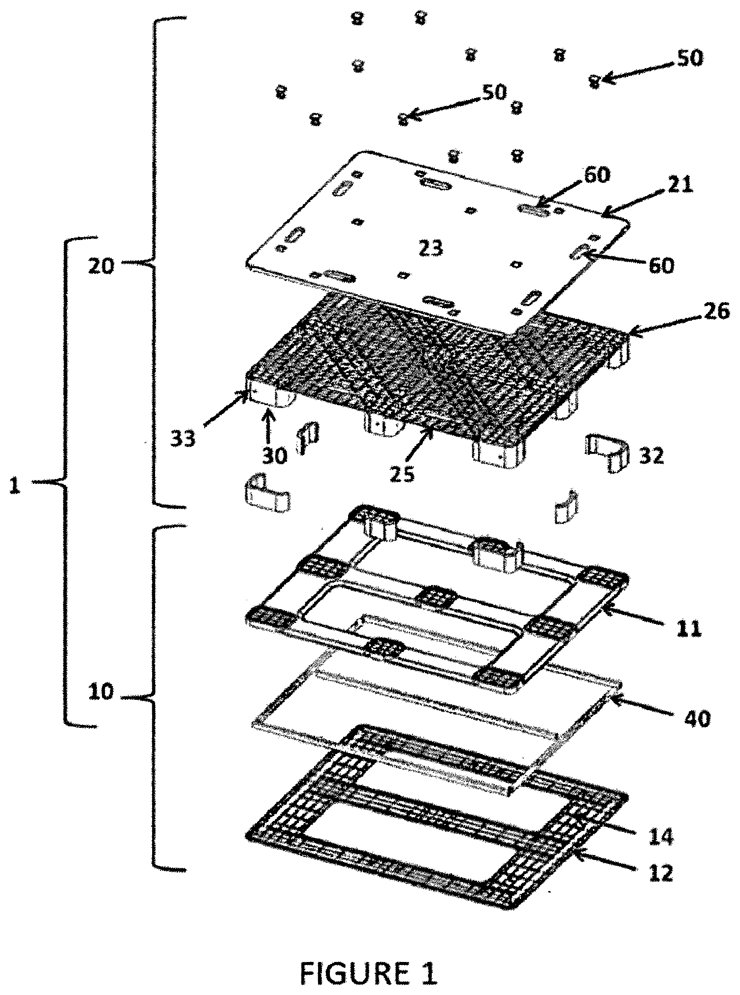
[0015] FIG. 1 shows a top frontal perspective exploded view of the instant invention, illustrating all the decks of the pallet of the instant invention.
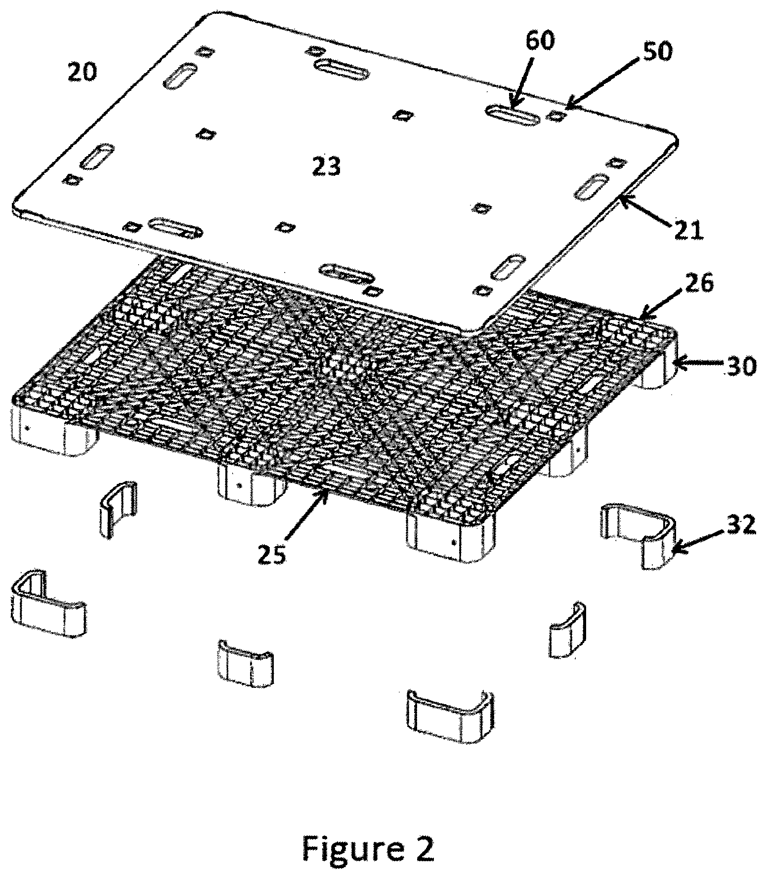
[0016] FIG. 2 shows a top frontal perspective exploded view of the top deck of the instant invention.
[0017] FIG. 3 shows a top frontal perspective exploded view of the bottom deck of the instant invention.
[0018] FIG. 4 shows a detailed section of the assembled pallet of the instant invention.
[0019] FIG. 5 shows a detailed section (F) of the post of the assembled pallet of the instant invention.
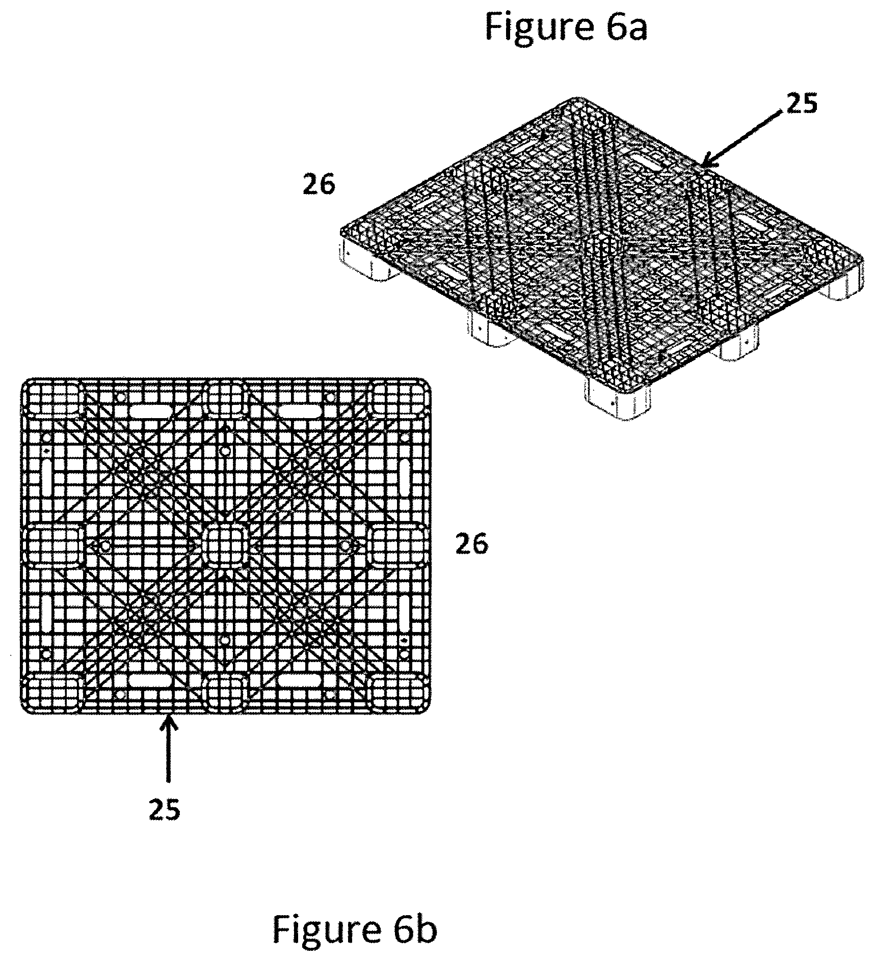
[0020] FIG. 6a shows a top frontal perspective view of the lower portion of the top deck of the instant invention illustrating the ribs and walls layout thereof.
[0021] FIG. 6b shows a top plain view of the lower portion of the top deck of the instant invention illustrating the ribs and walls layout thereof.
[0022] FIG. 7a shows a top frontal perspective view of the lower portion of the bottom deck of the instant invention illustrating the ribs and walls layout and the reinforcements beam layout thereof.
[0023] FIG. 7b shows a top plain view of the lower portion of the bottom deck of the instant invention illustrating the ribs and walls layout and the reinforcements beam layout thereof.
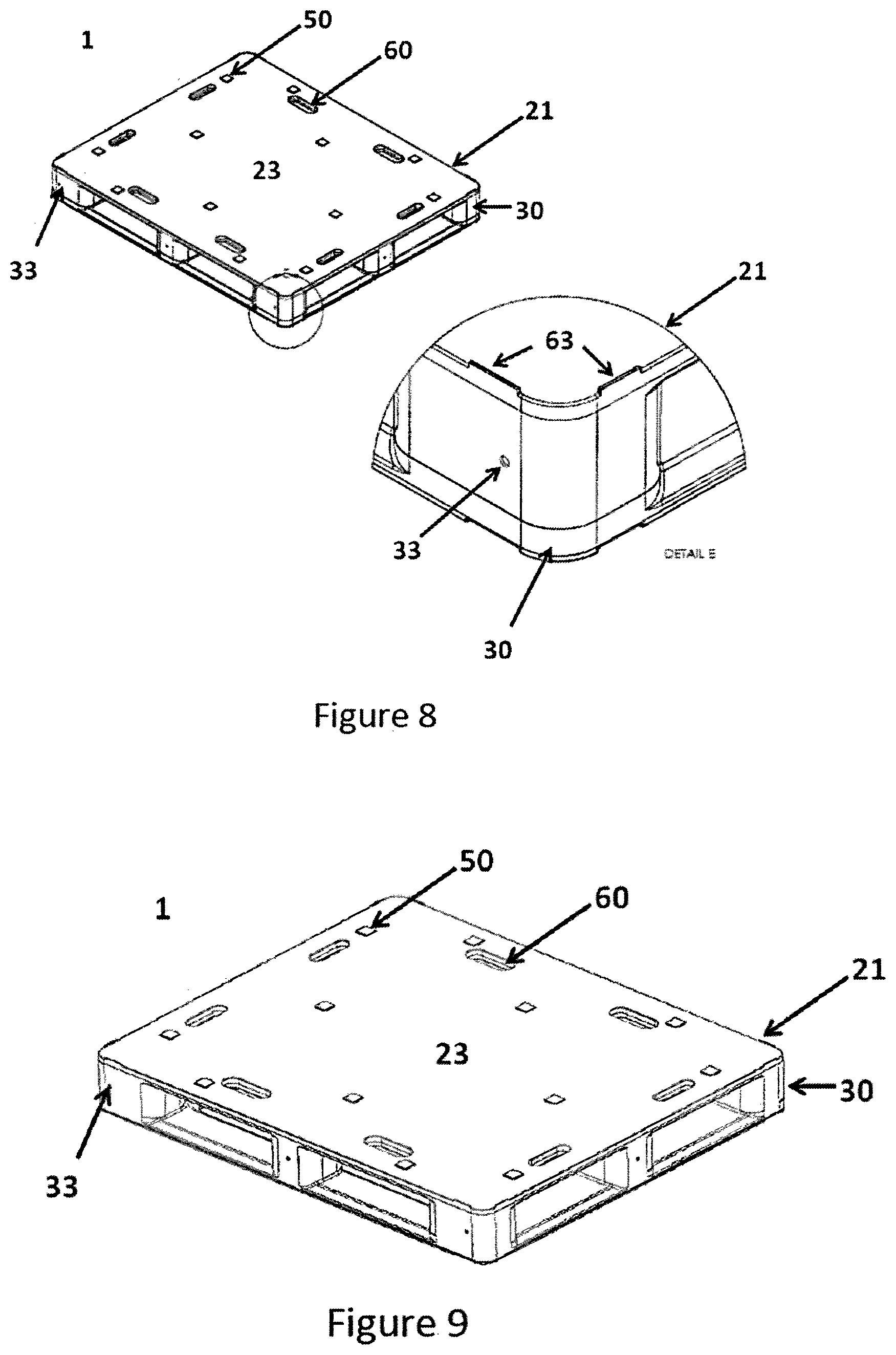
[0024] FIG. 8 shows a detailed view (E) of the nesting lips according to a preferred embodiment of the instant invention.
[0025] FIG. 9 shows a top frontal perspective view of the plastic pallet of the instant invention already assembled.
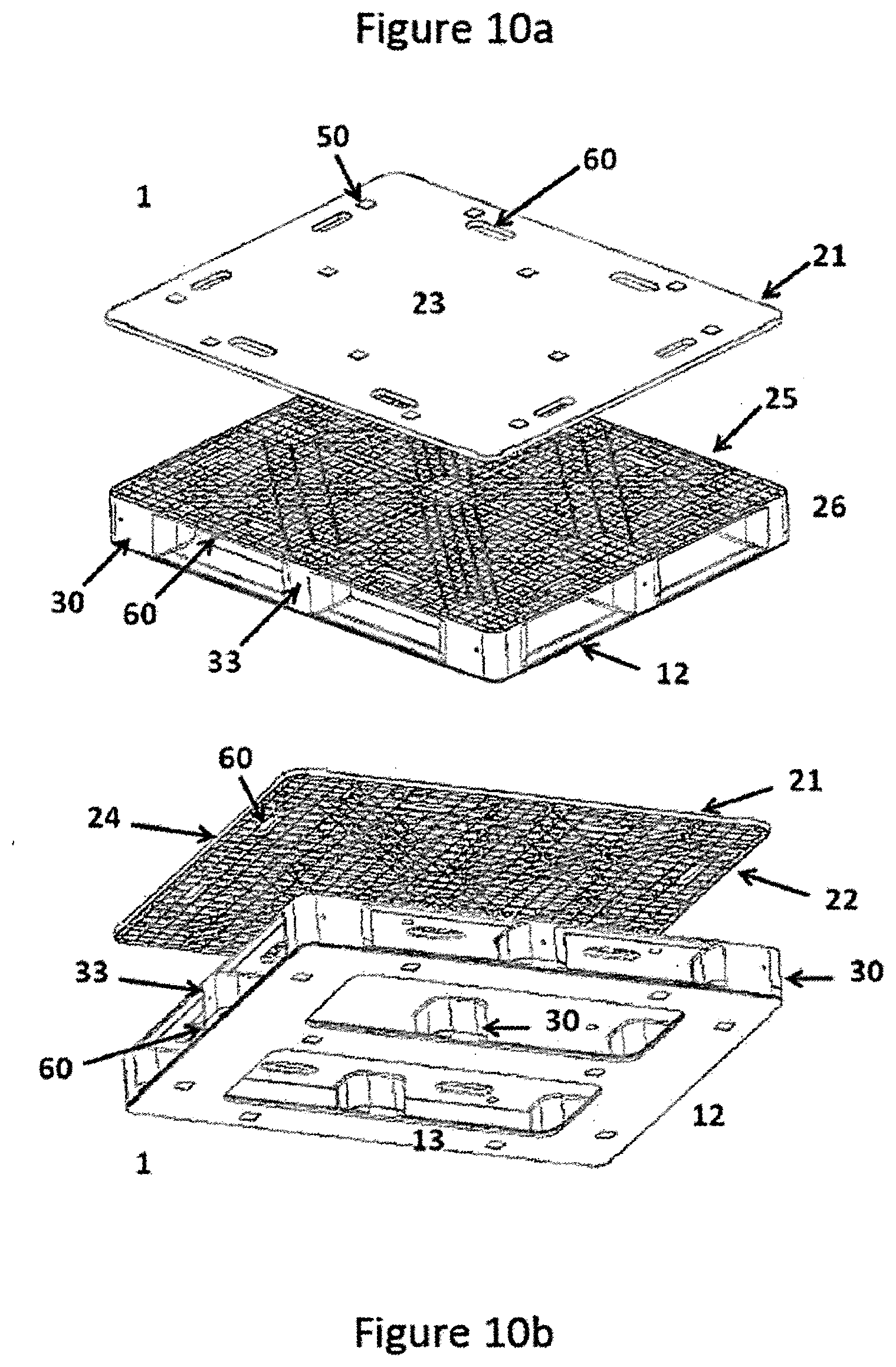
[0026] FIG. 10a shows a top frontal perspective view of the plastic pallet of the instant invention, removing the upper portion of the top deck.
[0027] FIG. 10b shows a bottom frontal view of the plastic pallet of the instant invention, removing the upper portion of the top deck.
[0028] FIG. 11 shows a top frontal perspective view of the plastic pallet of the instant invention partially removing a detail of the top portion of the top deck.
[0029] FIG. 12 shows a bottom frontal perspective view of the assembled plastic pallet of the instant invention.
[0030] FIG. 13 shows a bottom frontal perspective view of the plastic pallet of the instant invention, partially removing the lower portion of the bottom deck and illustrating a detail (G) of the corner upper portion of the bottom deck.
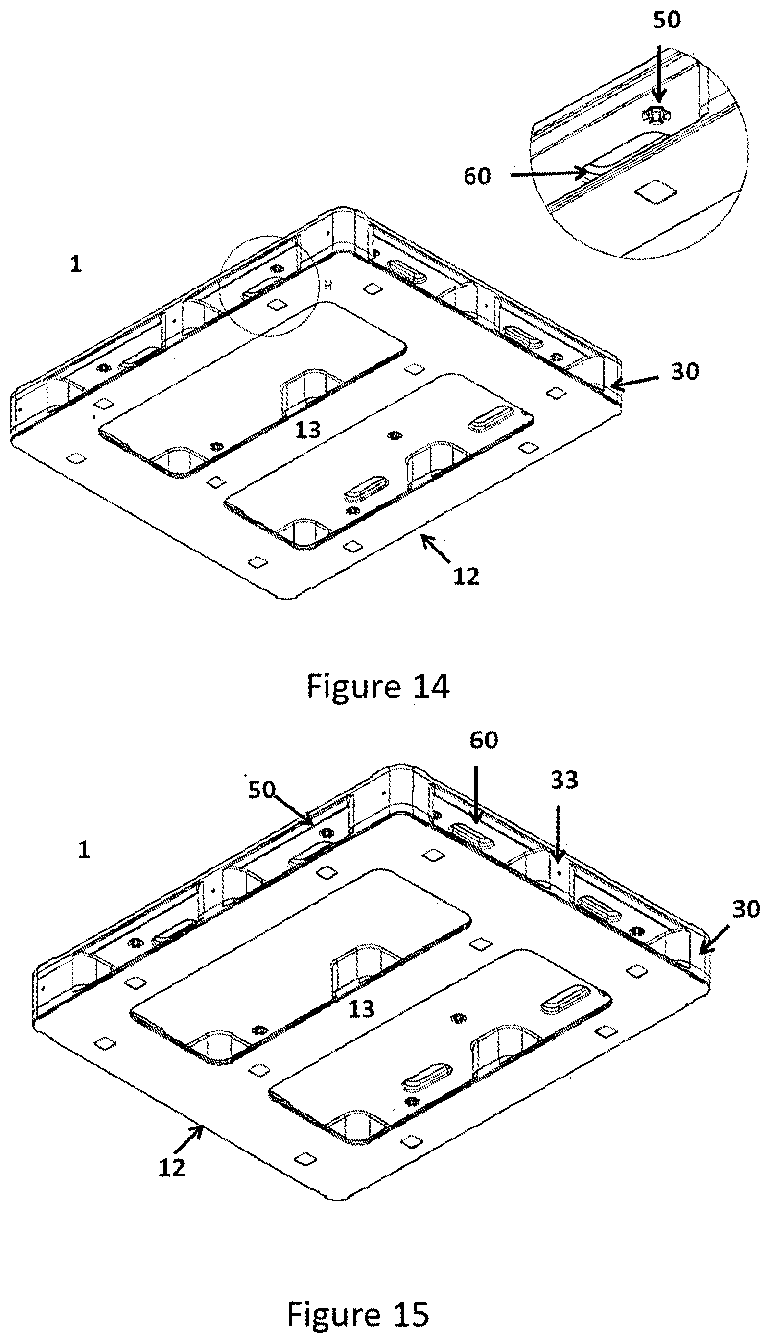
[0031] FIG. 14 shows a bottom frontal perspective view of the plastic pallet of the instant invention, illustrating a detail (H) of the assembly of the anti-slip rubbers.
[0032] FIG. 15 shows a bottom front perspective view of the plastic pallet without reinforcements, according to a preferred embodiment of the instant invention.
[0033] FIG. 16 shows a bottom front perspective view of the plastic pallet without reinforcements, according to a preferred embodiment of the instant invention, as well as a detail view of the upper portion of the bottom deck without reinforcements.
[0034] FIG. 17 shows a detailed view of the post portion of the plastic pallet without reinforcements according to an embodiment of the instant invention.
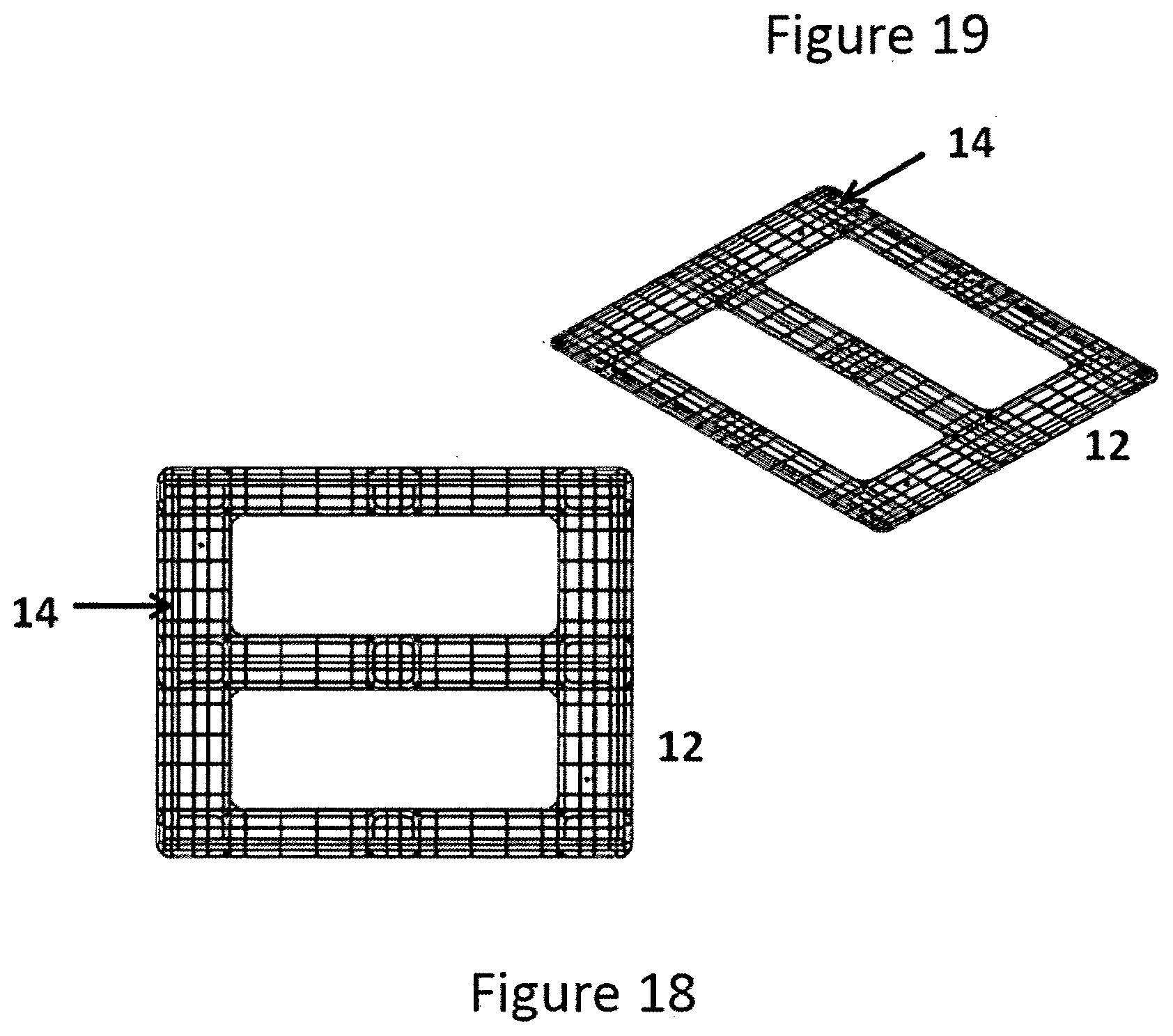
[0035] FIG. 18 shows a top plain view of the lower portion of the bottom deck without reinforcements according to a preferred embodiment of the instant invention.
[0036] FIG. 19 shows a top side perspective view of the lower portion of the bottom deck without reinforcements according to a preferred embodiment of the instant invention.
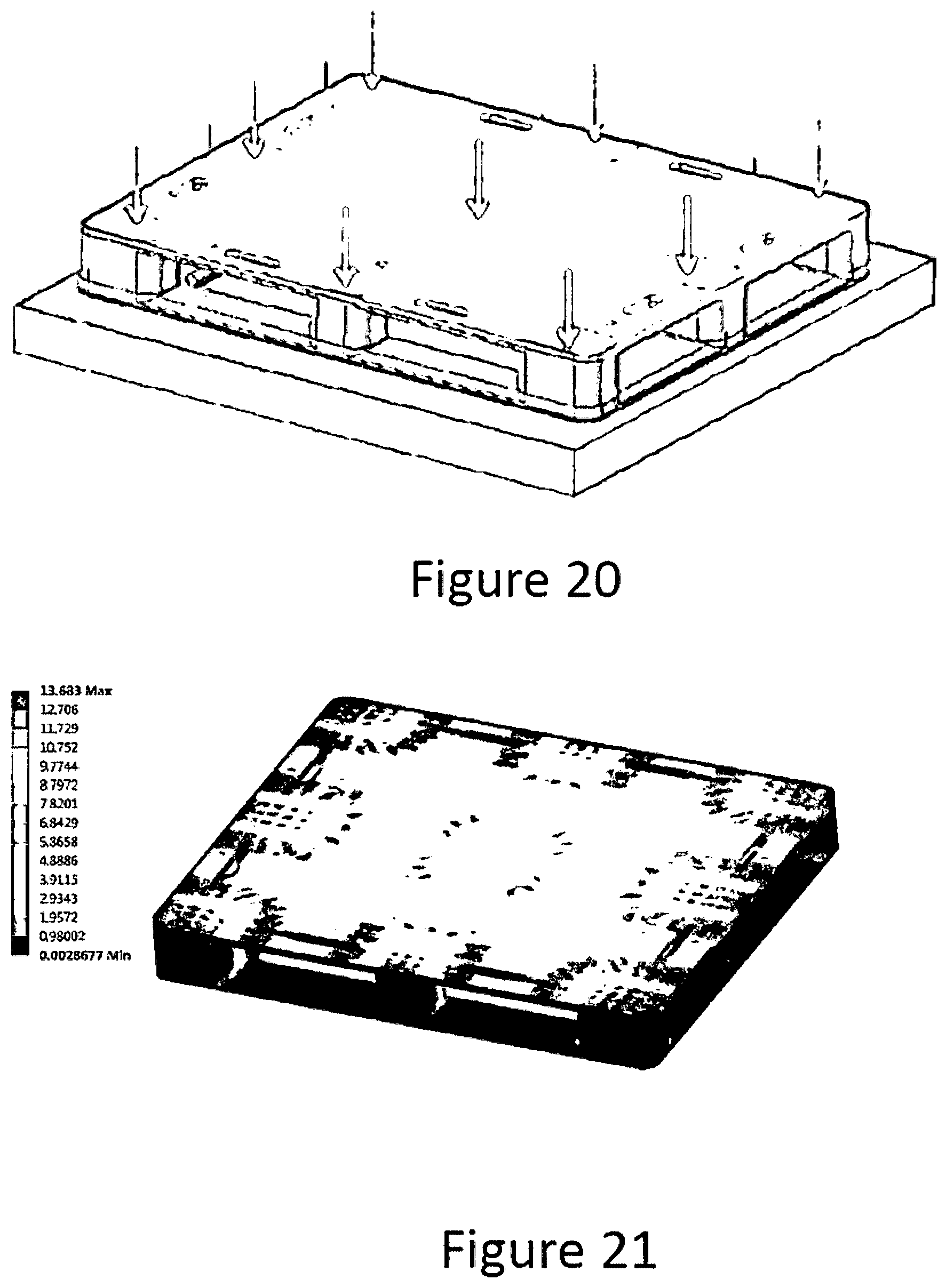
[0037] FIG. 20 shows the static load distribution on the top surface of the pallet during the FEA (Finite Element Analysis) test.
[0038] FIG. 21 shows a perspective view of the stress results on a pallet according to the instant invention during the FEA static load test.
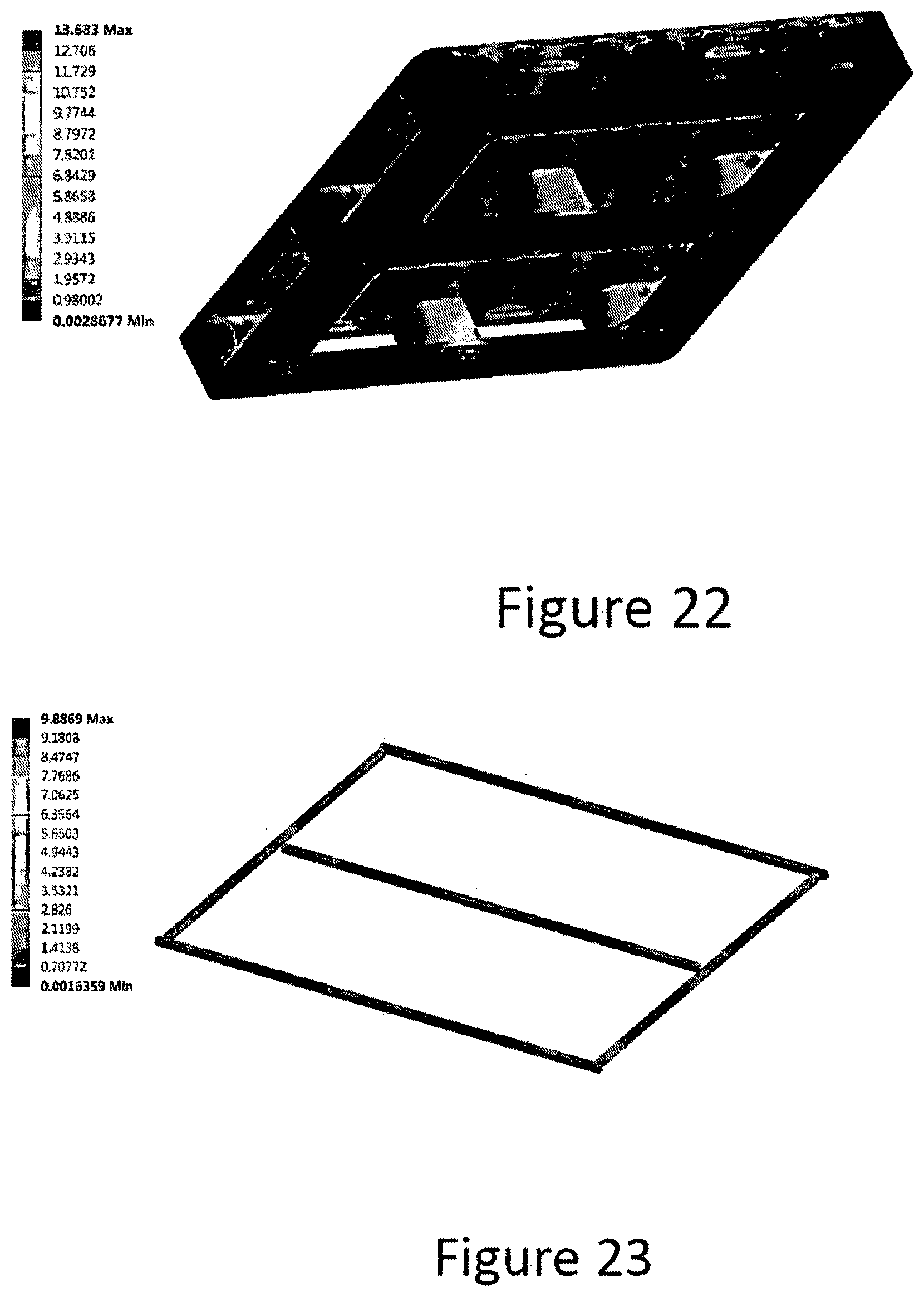
[0039] FIG. 22 shows the total stress in plastic on a pallet according to the instant invention during the FEA static load test.
[0040] FIG. 23 shows the total stress in aluminum on a pallet according to the instant invention during the FEA static load test.
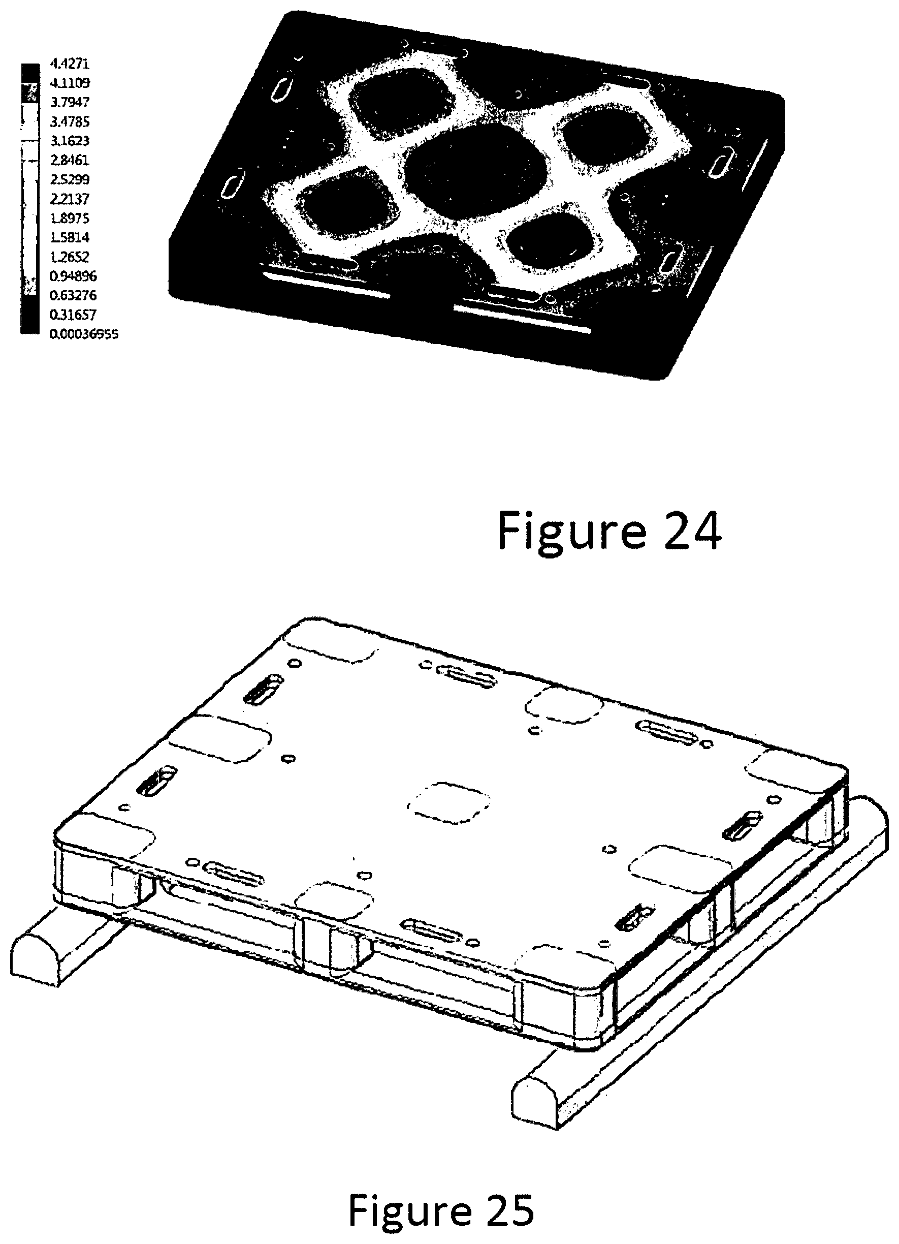
[0041] FIG. 24 shows the total displacement results on a pallet according to the instant invention during the FEA static load test.
[0042] FIG. 25 shows the racking load distribution on the top surface of the pallet during the FEA test.
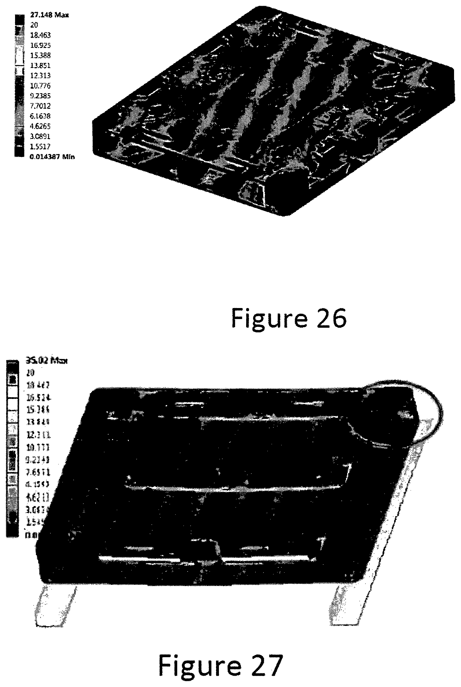
[0043] FIG. 26 shows a perspective view of the stress results on a pallet according to the instant invention during the FEA racking load test.
[0044] FIG. 27 shows the total stress in plastic on a pallet according to the instant invention during the FEA racking load test.
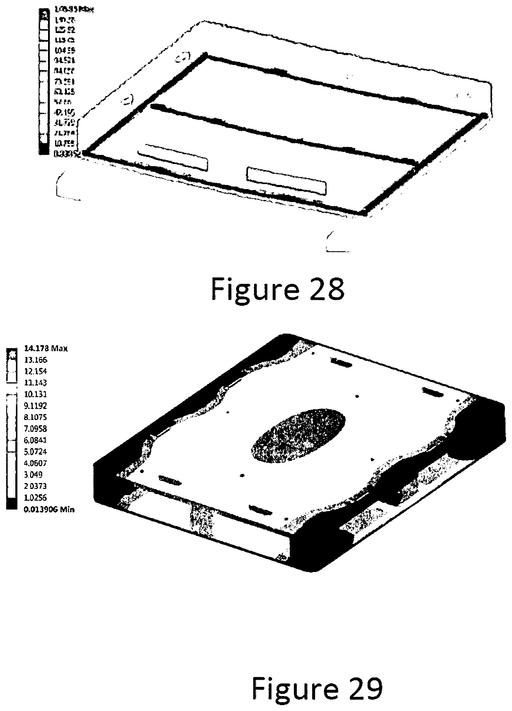
[0045] FIG. 28 shows the total stress in aluminum on a pallet according to the instant invention during the FEA racking load test.
[0046] FIG. 29 shows the total displacement results on a pallet according to the instant invention during the FEA racking load test.
[0047] FIG. 30 shows the dynamic load distribution on the top surface of the pallet during the FEA test.
[0048] FIG. 31 shows the total stress in plastic on a pallet according to the instant invention during the FEA dynamic load test.
[0049] FIG. 32 shows the total stress in aluminum on a pallet according to the instant invention during the FEA dynamic load test.
[0050] FIG. 33 shows the total displacement results on a pallet according to the instant invention during the FEA dynamic load test.
[0051] FIG. 34 shows the Inverted load distribution on the top surface of the pallet during the FEA test.
[0052] FIG. 35 shows the total stress in plastic on a pallet according to the instant invention during the FEA inverted load test.
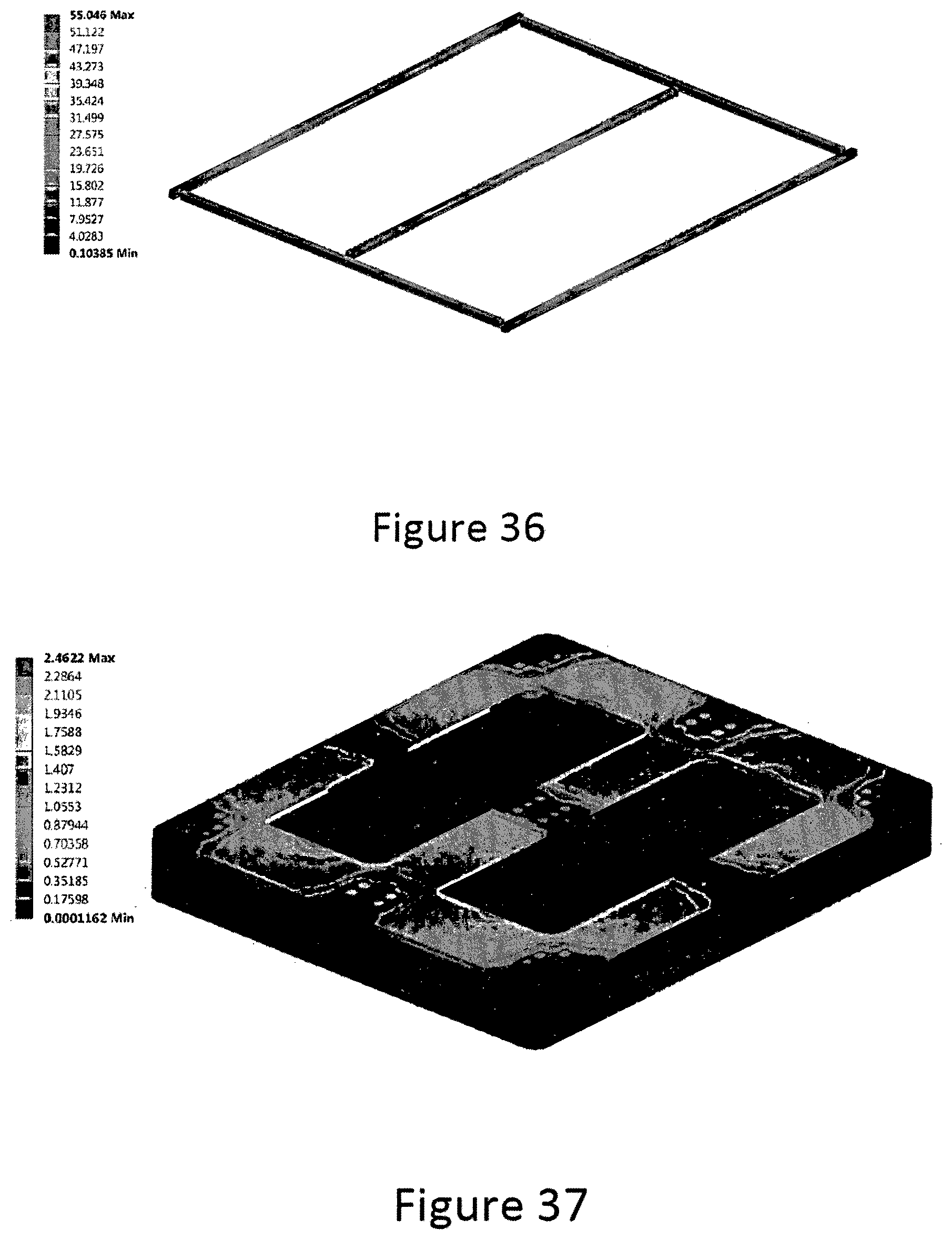
[0053] FIG. 36 shows the total stress in aluminum on a pallet according to the instant invention during the FEA inverted load test.
[0054] FIG. 37 shows the total displacement results on a pallet according to the instant invention during the FEA inverted load test.
DETAILED DESCRIPTION OF THE INVENTION
[0055] The present invention is referred to an improved plastic pallet. Such improvement is accomplished by strategically reinforcing in each of its layers and components, by means of a structure of inner ribs and walls, by providing the possibility of injecting a plastic foam in vulnerable places of the pallet and the insertion of beams of a material that is more rigid than the material of the pallet inside the components of said pallet.
[0056] In further embodiments of the instant invention, the plastic pallet can be provided without the injection of the plastic foam, which would facilitate the manufacture and lower the weight thereof.
[0057] As shown in FIG. 1, in an embodiment of the invention, the improved plastic pallet (1) of the present invention is manufactured in parts which are mainly:
[0058] A bottom deck (10) shown in FIG. 3: The bottom deck (10) of the plastic pallet of the instant invention is comprised of two molded pieces (11, 12).
[0059] The bottom most part of said bottom deck (10) is the lower portion (12) of said bottom deck, which works as a bottom deck cover, said lower portion (12) comprises a smooth surface (13) at the bottom most part of the lower portion, such smooth surface (13) will serve as a base for the plastic pallet (1). On the upper side of said lower, portion (12), it is provided an arrangement of ribs and walls (14) which work as support for the bottom deck (10).
[0060] The upper portion of the bottom deck (11) also has a corresponding arrangement of ribs and walls (15) that together with the bottom deck cover will provide support for the bottom portion.
[0061] The bottom deck (11) and the bottom deck cover (12) are welded together. Alternatively, both pieces are joined together using staples or any other mean for fixation available for the person skilled in the art.
[0062] A top deck (20) shown in FIG. 2: the top deck (20) of the plastic pallet (1) is comprised of two molded pieces (21, 22).
[0063] As shown in FIGS. 1 and 2, the upper most part of said top deck (20) is an upper portion (21) of the top deck, which works as a top deck cover, the uppermost side (23) of such upper portion (21) provides a smooth surface for supporting the load of the pallet. The lower side of said upper portion (21) has an arrangement of ribs and walls (24) which provide support for the top deck (20).
[0064] As shown in FIG. 2, the lower part of said top deck (20) is the lower portion (22). Such upper portion (22) comprises an arrangement of ribs and walls (25) corresponding to that of the top deck cover. Likewise, said lower portion (21) comprises a set of post portions (30).
[0065] As shown in FIG. 4, each one of said post portions (30) forms a cavity (31) which can be injected with a plastic foam (32), according to a preferred embodiment of the instant invention. The foam will provide an improved resistance towards impact to the posts, such resistance is especially important when the pallet is engaged by a fork lift, wherein a direct impact of the forks of the fork lift could occur and consequently damage the posts (30). The injection of the plastic foam (32) considerably reduces the damage produced to the posts (30) due to the impact of the fork lift forks.
[0066] As shown in FIG. 5, according to a further embodiment of the invention, a person skilled in the art could choose from amongst many possibilities, that each one of said post portions (30) is provided with at least one injection port (33) which will receive the nozzles that will inject a plastic foam to completely fill the cavity (31) of the posts (30) to reinforce them.
[0067] Likewise, the lower portion (22) of the top deck (20) and the upper portion (21) of the top deck (20) are welded together. Alternatively, both pieces are joined together using staples or any other mean for fixation available for the person skilled in the art.
[0068] On a further embodiment of the instant invention, a set of reinforcement beams (40) is embedded between said lower portion (11) of the bottom deck (10) and said upper portion (12) of the bottom deck (10). Such reinforcement beams (40) provide strength to bending, an improved resistance towards compression and an improve rigidity of the bottom portion.
[0069] According to FIGS. 15 to 19, a preferred embodiment of the invention is shown without using reinforcements beams or inserts. Such beams or inserts can be beams of the same material of the pallet or they can be manufactured from a more rigid material. Preferably; such beams or inserts are made of a metallic material with low weight and high resistance to bending. More preferably, the beams or inserts are made of aluminum or any material with similar characteristics.
[0070] On the other hand, according to FIGS. 7a and 7b, one or a plurality of further reinforcement beams or inserts can be placed on the bottom portion of the plastic pallet.
[0071] On a further embodiment of the instant invention, shown in FIG. 3, said upper portion (12) of the bottom deck (10) and said lower portion (11) of the deck cover (10) are two plane surfaces arranged in a sandwich structure, wherein both surfaces are joined together by means of a rib arrangement (14).
[0072] Likewise, said lower portion (22) of the top deck (20) and said lower portion (21) of the top deck (20) are two plane surfaces arranged in a sandwich structure, wherein both surfaces are joined together by means of a rib and walls arrangement (25) in the form of a grid or a double cross arrangement.
[0073] Said sandwich structure is obtained by joining two pieces with plane surfaces together by fusion (hot-plate welding) thereof through the corresponding ribs and walls (14, 25).
[0074] Welding both pieces together provides an improved rigidity or strength to flexion of the plane surfaces as a result of its connection through the welded ribs. Likewise, such arrangement distributes the shear forces, the bending forces and the compression forces along the whole surfaces, avoiding the accumulation of forces on a small surface of the pallet. This arrangement allows the material to efficiently absorb the forces minimizing the damage to the pallet assembly (1).
[0075] In order to facilitate the manufacture process, conventional pallets are provided with only an upper plane surface with ribs on its bottom part. Likewise, other conventional pallets show only ribs without plane surfaces.
[0076] An improved rigidity on the pallet surfaces reduces the damage produced to the mobilized product due to excessive deformation of the unit load during the warehouse stacking and transport operations.
[0077] In yet another embodiment of the instant invention, said rib arrangement either on the bottom deck (14) or in the top deck (25) of the pallet is a structure of walls arranged diagonally and crossing each other.
[0078] Such crossing provides strength and torsional stiffness to the areas in between, while maintaining a soft plain surface on the top portion of the top deck.
[0079] The crossed ribs are directly connected to the posts of the pallet in the top deck portion, in order to provide an improved rigidity to the area between the posts, which is the space with the larger deformations, during the transportation and manipulation of the load unit.
[0080] Such cross elements allow the instant invention to fulfill the norms regarding the limits on deformations of the pallets, during mobilization and stacking of the pallets, i.e. when the pallet is under static load. Such deformations could damage the load unit. By preventing the deformation, the damage due to deformations transmitted to the loaded product are minimized.
[0081] In another embodiment of the invention, the walls of the rib arrangement connect the pallet posts, either on the bottom, the top portion or in both portions of the plastic pallet.
[0082] Likewise, as shown in FIG. 14, it is possible that the top portion comprises openings for receiving anti slip rubbers (50). Such anti-slip rubbers provide a surface to avoid slipping of the merchandise loaded on the pallet.
[0083] In a further embodiment of the invention, the top portion comprises integrated handholds (60), to facilitate its handling.
[0084] In yet another embodiment, the top and bottom portions comprise smooth surfaces (61, 62).
[0085] Likewise, in a further embodiment of the invention, it is possible that in the top and bottom portions of the plastic pallet to arrange nesting lips (63) in the corners, as shown in FIG. 8.
[0086] In further embodiments of the instant invention, the material of the pallet can be rigidified by including a reinforced material such as fibers or mineral fillings.
EXPERIMENTAL RESULTS
[0087] The following table shows a summary of a Finite Element Analysis test carried out on a preferred embodiment of the instant invention.
[0088] For the FEA, the following load requirements were considered:
[0089] Static. 1,270 kg (2,800 lb) per pallet, at 5 stacks 6,350 kg (14,000 lb).
[0090] Racking. 1,270 kg (2,800 lb)
[0091] Dynamic. 2,540 kg (5,600 lb)
[0092] The following Material properties were used:
[0093] HDPE:
[0094] Young modulus 1,300 Mpa
[0095] Poisson's ratio 0.4
[0096] Yield strength 30 Mpa
[0097] Aluminum:
[0098] Young modulus 69,000 Mpa
[0099] Poisson's ratio 0.4
[0100] Yield strength 289 Mpa
[0101] For static load, it is considered a load of 6,350 kg (14,000 lb) corresponding to 5 stacks of 2,800 lb (see FIG. 20).
[0102] The stress results can be observed in FIG. 21 wherein the total stress in the pallet product is shown.
[0103] Likewise, the total stress distribution in plastic of 13.68 MPa is shown in FIG. 22.
[0104] The total stress distribution in aluminum of 9.88 MPa is shown in FIG. 23.
[0105] The total displacement distribution of 4.42 mm is shown in FIG. 24.
[0106] For racking, it is considered a load of 1,270 kg (2,800 lb) on the complete surface of the pallet uniformly distributed (see FIG. 25).
[0107] The stress results can be observed in FIG. 26 wherein the total stress in the pallet product is shown.
[0108] Likewise, the total stress distribution in plastic of 35.02 MPa is shown in FIG. 27.
[0109] The total stress distribution in aluminum of 146.85 MPa is shown in FIG. 28.
[0110] The total displacement distribution of 13.59 mm is shown in FIG. 29.
[0111] For dynamic, it is considered a load of 2,540 kg (5,600 lb) on the complete surface of the pallet uniformly distributed (see FIG. 30).
[0112] The total stress distribution in plastic of 11.73 MPa is shown in FIG. 31.
[0113] The total stress distribution in aluminum of 21.03 MPa is shown in FIG. 32.
[0114] The total displacement distribution of 4.97 mm is shown in FIG. 33.
[0115] For inverted static load, it is considered a load of 5,080 kg (11,200 lb) corresponding to 4 stacks of 2,800 lb (see FIG. 34).
[0116] The total stress distribution in plastic of 14.68 MPa is shown in FIG. 35.
[0117] The total stress distribution in aluminum of 55.04 MPa is shown in FIG. 36.
[0118] The total displacement distribution of 2.46 mm is shown in FIG. 37.
[0119] List of Elements
[0120] We provide herein below a list of the elements with its corresponding number:
TABLE-US-00001 1 Plastic Pallet Assembly 10 Bottom deck 11 Upper portion of the bottom deck 12 Lower portion of the bottom deck 13 Smooth surface 14 Bottom deck rib arrangement 20 Top deck 21 Upper portion of the top deck 23 Top surface of the upper portion of the top deck 25 Top deck ribs and walls arrangement 30 Posts 31 Post cavity 32 Injected foam 33 Injection port 40 Reinforcement beams or inserts 50 Anti-slip rubbers 60 Hand holds 61, 62 Smooth surfaces 63 Nesting lips
* * * * *
D00000
D00001
D00002
D00003
D00004
D00005
D00006
D00007
D00008
D00009
D00010
D00011
D00012

D00013
D00014
D00015
D00016
D00017
D00018
D00019

D00020

D00021

D00022
XML
uspto.report is an independent third-party trademark research tool that is not affiliated, endorsed, or sponsored by the United States Patent and Trademark Office (USPTO) or any other governmental organization. The information provided by uspto.report is based on publicly available data at the time of writing and is intended for informational purposes only.
While we strive to provide accurate and up-to-date information, we do not guarantee the accuracy, completeness, reliability, or suitability of the information displayed on this site. The use of this site is at your own risk. Any reliance you place on such information is therefore strictly at your own risk.
All official trademark data, including owner information, should be verified by visiting the official USPTO website at www.uspto.gov. This site is not intended to replace professional legal advice and should not be used as a substitute for consulting with a legal professional who is knowledgeable about trademark law.