Transport Unit
BRETZ; Markus
U.S. patent application number 16/419934 was filed with the patent office on 2019-11-28 for transport unit. This patent application is currently assigned to WRH WALTER REIST HOLDING AG. The applicant listed for this patent is WRH WALTER REIST HOLDING AG. Invention is credited to Markus BRETZ.
| Application Number | 20190359377 16/419934 |
| Document ID | / |
| Family ID | 66483948 |
| Filed Date | 2019-11-28 |


| United States Patent Application | 20190359377 |
| Kind Code | A1 |
| BRETZ; Markus | November 28, 2019 |
TRANSPORT UNIT
Abstract
A rollingly conveyable transport unit (1) comprises a container shell (10) and an internal space (28), provided within the container shell, for accommodating a product (90) to be packaged. The container shell comprises two or more shell parts (11, 12) that are reversibly connected to one another in a force-fit manner by a closing element.
| Inventors: | BRETZ; Markus; (Herrliberg, CH) | ||||||||||
| Applicant: |
|
||||||||||
|---|---|---|---|---|---|---|---|---|---|---|---|
| Assignee: | WRH WALTER REIST HOLDING AG CH-8272 ERMATINGEN CH |
||||||||||
| Family ID: | 66483948 | ||||||||||
| Appl. No.: | 16/419934 | ||||||||||
| Filed: | May 22, 2019 |
| Current U.S. Class: | 1/1 |
| Current CPC Class: | B65D 81/07 20130101; B65D 11/20 20130101; B65D 11/02 20130101; B65D 81/075 20130101; B65D 11/10 20130101; B65D 2565/38 20130101; B65D 81/113 20130101; B65B 61/22 20130101 |
| International Class: | B65D 6/00 20060101 B65D006/00; B65D 8/00 20060101 B65D008/00; B65B 61/22 20060101 B65B061/22; B65D 81/07 20060101 B65D081/07; B65D 81/113 20060101 B65D081/113 |
Foreign Application Data
| Date | Code | Application Number |
|---|---|---|
| May 22, 2018 | CH | 00636/18 |
Claims
1. A rollingly conveyable transport unit (1, 101, 201, 301, 401, 501) comprising: a container shell (10, 110, 210, 310, 410, 510) and an internal space, provided within the container shell, the internal space for accommodating a product (90) to be packaged, wherein the container shell comprises two or more shell parts (11, 12, 111, 112, 211, 212, 311, 312, 411, 412, 511, 512) that are reversibly connected to one another in a force-fit manner by a closing element.
2. The transport unit according to claim 1, wherein the closing element is situated within the container shell.
3. The transport unit according to claim 1, wherein the shell parts (11, 12, 111, 112, 211, 212, 311, 312) are mutually connectable to form a volume (29, 129, 229, 329) inside the transport unit that is pressure-tightly sealed; and wherein at least one valve element (15, 115, 215, 315) is provided, with which said pressure-tightly sealed volume is reversibly fluidically connectable to an external space (27).
4. The transport unit according to claim 3, wherein the at least one valve element (15, 115, 215, 315) is situated on a shell part (11, 12, 111, 112, 211, 212, 311, 312).
5. The transport unit according to claim 1, wherein the container shell (10, 110, 210, 310) comprises two shell parts (11, 12, 111, 112, 211, 212, 311, 312) that are connected by a sealing element (17, 117, 217, 317a, 317b) in a fluid-tight manner and that form a volume (29, 129, 229, 329) that is pressure-tightly sealed.
6. The transport unit according to claim 5, wherein at least one additional internal space is present that is not pressure-tightly sealed with respect to the outside atmosphere.
7. The transport unit according to claim 5, wherein at least one additional internal space is present that is fluidically connected to the first internal space.
8. The transport unit according to claim 1, wherein the closing element includes magnetic elements (350a, 350b, 450a, 450b, 551a, 551b) that reversibly connect the at least two shell parts (311, 312, 411, 412, 511, 512) to one another in a force-fit manner.
9. The transport unit according to claim 1, wherein a hollow cylinder is situated on the inner wall of two or more shell elements.
10. The transport unit according to claim 1, further comprising an adapter device with which the product (90) is fixable within the container shell in a form-fit and/or force-fit manner.
11. The transport unit according to claim 10, wherein the adapter device includes a film wrapping (140) around the product (90).
12. The transport unit according to claim 10, wherein the adapter device includes two hollow cylinders, each situated at the inner wall of a shell element, and two flexible and/or elastic layers that each cover an opening of a hollow cylinder.
13. The transport unit according to claim 1, wherein the container shell (10, 110, 210, 310, 410, 510) has the shape of a rollable body.
14. The transport unit according to claim 1, wherein the container shell (10, 110, 210, 310, 410, 510) has a spherical, cylindrical, barrel-shaped, or double cone-shaped external shape.
15. The transport unit according to claim 1, wherein two or more of the shell elements of the transport unit are identical to one another.
16. The transport unit according to claim 1, with a product (90) that is fixed in a form-fit manner and/or in a force-fit manner and/or with frictional engagement in the internal space of the container shell (10, 110, 210, 310, 410, 510).
17. The transport unit according to claim 16, wherein the product (90) is fixed in the container shell (10, 110, 210, 310, 410, 510) by means of an adapter device.
18. The transport unit according to claim 1, wherein the container shell is closed so that the transport unit is floatable, in particular in water.
19. A kit including at least one rollingly conveyable transport unit according to claim 1 and at least one adapter device for fixing a product (90) in the internal space of a rollingly conveyable transport unit.
20. A kit for producing a rollingly conveyable transport unit according to claim 1, comprising two or more shell parts that are reversibly connectable to one another in a force-fit manner by a closing element to form a container shell.
21. A method for producing a rollingly conveyable transport unit with a product packaged therein, comprising the steps: providing a rollingly conveyable transport unit according to claim 1, having two or more shell parts; providing a product to be packaged in the transport unit; introducing the product to be packaged into an inner space of the transport unit; and connecting the shell parts in a force-fit manner to form a container shell.
22. The method according to claim 20, wherein the transport unit is a rollingly conveyable transport unit with reference to claim 3; the shell parts are joined to form a container shell, forming a volume that is sealed pressure-tight in the inner space of the transport unit; and a pressure difference is created between the pressure-tightly sealed volume and the external space.
Description
CROSS-REFERENCE TO RELATED APPLICATIONS
[0001] Swiss Patent Application 00636/18, filed 22 May 2018, the priority documents corresponding to this invention, to which a foreign priority benefit is claimed under Title 35, United States Code, Section 119, and Title 37, United States Code, Section 1.55, and their entire teachings are incorporated, by reference, into this specification.
BACKGROUND OF THE INVENTION
Field of the Invention
[0002] The invention relates to transport units having a container shell and an internal space, provided within the container shell, for accommodating a product to be packaged, and a method for producing such transport units.
Discussion of Related Art
[0003] As the result of steadily increasing volumes of online commerce, dealers, suppliers, and logistics companies must efficiently handle the goods to be processed, in particular with regard to manufacture, provision, and storage of the articles, as well as order picking and transporting the articles to customers.
[0004] Many goods, for example household appliances, consumer electronics, foods, pharmaceuticals, clothing, shoes, books, media data carriers such as CDs and DVDs, etc., are already provided with their own packaging by the manufacturer, and optionally combined into larger units that are provided on pallets, for example. These pallets are typically moved using forklifts, loaded onto or unloaded from trucks, and stored with a dealer and retrieved as needed.
[0005] In certain areas of intralogistics, automated high rack warehouses are used which are operated by automated loading devices and unloading devices in the aisles between the individual racks. This type of storage is complicated by the fact that at a storage area, the most recently stored goods, for example an entire pallet, must usually be the first retrieved, since the racks may typically be filled and emptied from only one side. In addition, storage and retrieval of the goods is slow and inefficient, since an appropriate control device must be moved over large distances in the horizontal and vertical directions in order to store or retrieve an article.
[0006] If the goods are combined into larger units and transported on standard pallets, such a larger unit must be taken apart in order to provide individual pieces of the goods for further processing, for example in storage containers of an automated small parts warehouse.
[0007] WO 2014/191106 A1 discloses an automatable storage system for transport units that are designed as rollable bodies, having warehousing devices for storing multiple rollable transport units, storage devices for receiving and bringing transport units to the warehousing devices, and retrieval devices for removing the transport units that are stored in the warehousing devices. Such a storage system allows, for example, building up an efficient small parts warehouse in which the goods, which are individually packaged in rollable transport units, may be efficiently processed, managed, and order picked.
[0008] The use of rollable transport units provides the advantage in particular that the transport units may be conveyed over large distances, driven by gravity, without an active drive. In addition, the shape of a rolling body facilitates automatic processing in conveying systems and storage systems.
[0009] WO 2014/191107 A1 discloses a rollable transport unit in which the center of gravity of the transport unit filled with goods may be centered to optimize the rolling movement during conveying.
[0010] U.S. Pat. No. 6,050,438 discloses a spherical, thin-walled, divided capsule for accommodating an article. The capsule may be nondestructively separated, the parts having mutually engaging closure elements that establish a stable connection of the parts, so that the capsule is suitable for use in vending machines. WO 2014/191105 A1 discloses a further rollable transport unit in which the shape of the storage space of the packaging body is or may be adapted to the shape of a product to be accommodated in the packaging body.
[0011] There is a general need for improvements in this field.
SUMMARY OF THE INVENTION
[0012] It is an object of the invention to provide a transport unit of the type mentioned at the outset which does not have the above-mentioned and other disadvantages. In particular, the intent is for such a transport unit to be easily producible from individual parts. The transport unit is to be advantageously usable multiple times. It is to have a long service life and should be producible in a cost-effective manner.
[0013] Such a transport unit is to be advantageously installable or closable without adverse effects on the transport unit or its contents due to physical or chemical conditions, in particular without the effect of elevated temperatures. It should be possible for such a package to be closed without external or temporary holding means, or fixing means such as clamps or presses.
[0014] A further object of the invention is to provide a method with which transport units may be efficiently produced.
[0015] A further object of the invention is to provide a method with which transport units may be protectively and efficiently installed or closed without adverse effects on the transport unit or its contents due to physical or chemical conditions, in particular without the effect of elevated temperatures.
[0016] Yet a further object of the invention is to provide a method with which transport units may be closed without external or temporary holding means, or fixing means such as clamps or presses.
[0017] These and other objects are achieved by the elements of the independent claims. Further advantageous embodiments also arise from the dependent claims and the description.
[0018] The achievement of the object according to the invention may be further improved by various embodiments that are in each case advantageous on their own and, unless stated otherwise, combinable with one another as desired. These embodiments and their associated advantages are discussed below.
[0019] In the present description, the terms "products" and "goods" are used synonymously, and in particular may include individual piece goods and separatable or individually handleable articles in general, and thus, for example, also products that are already packaged in a closed package.
[0020] In the following description, the term "external space" is understood to mean the general surroundings of a transport unit in which standard atmospheric pressure prevails, as well as ambient temperature, in particular room temperature.
[0021] One aspect of the invention relates to a rollingly conveyable transport unit having a container shell and an internal space, provided within the container shell, for accommodating a product to be packaged, the container shell comprising two or more shell parts that are reversibly connected to one another in a force-fit manner by a closure or closing element(s).
[0022] In such a transport unit, the closing element is advantageously situated within the container shell. The arrangement of the closing elements within the container shell has the advantage, among others, that they are not directly accessible from the outside. Unintentional opening of the transport unit by external forces acting on the shell in an uncontrolled manner may thus be avoided.
[0023] The shell elements may be made, for example, from a suitable dimensionally stable plastic and/or from metal.
[0024] In one advantageous embodiment of a transport unit according to the invention, the mutually connected shell parts form a volume inside the transport unit that is pressure-tightly sealed. At least one valve element is provided, with which said pressure-tightly sealed volume is reversibly fluidically connectable to an external space.
[0025] The at least one valve element is advantageously situated on a shell element.
[0026] In another advantageous embodiment of a transport unit according to the invention, the container shell comprises two shell parts that are connected by a sealing element in a fluid-tight manner and that form a pressure-tightly sealed volume.
[0027] In the above-mentioned embodiment of a transport unit according to the invention, it is particularly advantageous for at least one additional internal space to be present that is not pressure-tightly sealed with respect to the outside atmosphere; or at least one additional internal space is present that is fluidically connected to the first internal space.
[0028] In a transport unit according to the invention, the closing element advantageously include magnetic elements that reversibly connect the at least two shell parts to one another in a force-fit manner.
[0029] A hollow cylinder may be situated on the inner wall of two or more shell elements of the transport unit.
[0030] In one advantageous embodiment variant of a transport unit according to the invention, an adapter device may be provided, with which the product is fixable within the container shell in a form-fit and/or force-fit manner.
[0031] The adapter device particularly advantageously includes a film wrapping around the product.
[0032] Alternatively or additionally, in such a transport unit the adapter device may include two hollow cylinders, each situated at the inner wall of a shell element, and two flexible and/or elastic layers that each cover an opening of a hollow cylinder.
[0033] The container shell advantageously has essentially the shape of a rollable body.
[0034] The container shell advantageously has a spherical, cylindrical, barrel-shaped, or double cone-shaped external shape.
[0035] Two or more of the shell elements of the transport unit are advantageously identical to one another.
[0036] A product that is fixed in a form-fit manner and/or in a force-fit manner and/or with frictional engagement is advantageously situated in the internal space of the container shell of a transport unit.
[0037] In such a transport unit, the product is particularly advantageously fixed in the container shell by means of an adapter device.
[0038] In another advantageous embodiment of a transport unit according to the invention, the container shell is essentially closed so that the transport unit is floatable, in particular in water. Such an embodiment variant allows in particular the conveying of such a transport unit in or on a fluid stream, for example in a pneumatic tube system or on flowing water.
[0039] Partial areas of the shell or the entire shell are/is advantageously transparent. This allows, among other things, the package contents to be identified and inspected without having to open the transport unit.
[0040] The transport unit may be provided with identification means, for example an optical code such as a one-dimensional or two-dimensional barcode, or a radio-frequency identification (RFID) element, in particular a near-field communication (NFC) RFID element.
[0041] An identification means may be integrated into the container shell, or may also be reversibly mounted in the shell interior. For example, an RFID element or an accompanying document having a barcode that is readable from the outside may be additionally enclosed with the packaged product.
[0042] Another aspect of the invention relates to a kit comprising at least one rollingly conveyable transport unit as discussed above, and at least one adapter device for fixing a product in the internal space of a rollingly conveyable transport unit.
[0043] A further aspect of the invention relates to a kit for producing a rollingly conveyable transport unit as discussed above, comprising two or more shell parts that are reversibly connectable to one another in a force-fit manner by a closing element to form a container shell.
[0044] Yet a further aspect of the invention relates to a method for producing a rollingly conveyable transport unit with a product packaged therein, comprising the steps: [0045] providing a rollingly conveyable transport unit as discussed above, having two or more shell parts; [0046] providing a product to be packaged in the transport unit; [0047] introducing the product to be packaged into an inner space of the transport unit; and [0048] connecting the shell parts in a force-fit manner to form a container shell.
[0049] In such a method according to the invention, the transport unit is advantageously a rollingly conveyable transport unit in which the mutually connected shell parts form a pressure-tightly sealed volume in the inner space of the transport unit, and at least one valve element is provided via which said pressure-tightly sealed volume is reversibly fluidically connectable to an external space; the shell parts are joined to form a container shell, forming a pressure-tightly sealed volume in the inner space of the transport unit; and a pressure difference is created between the pressure-tightly sealed volume and the external space.
[0050] Alternatively, the transport unit may also be assembled in an environment at a pressure that is lower than atmospheric pressure, for example a negative pressure chamber. When the assembled transport unit is then removed from the environment at a pressure that is lower than atmospheric pressure, the shell parts are held together by the pressure difference that is then present between the pressure-tightly sealed volume and the external space. Such a method allows, for example, valve elements on the transport units to be dispensed with.
[0051] It is particularly advantageous for the temperature in the inner space of the transport unit to remain unchanged during production of the transport unit, in particular when the transport unit is closed. The temperature is advantageously at ambient temperature, more advantageously is less than approximately 60.degree. C., and particularly advantageously is less than approximately 40.degree. C.
[0052] Instead of air, the inner space of the transport unit may be filled with some other gas or gas mixture, for example an inert gas such as nitrogen, argon, or carbon dioxide. This has the advantage that products that must be stored dry or under a protective atmosphere, for example, may also be packaged.
BRIEF DESCRIPTION OF SEVERAL VIEWS OF THE DRAWINGS
[0053] In order to facilitate a fuller understanding of the present invention, reference is now made to the appended drawings. These references are intended to be exemplary only and should not be construed as limiting the present invention to the features disclosed herein. Identical or similar reference numerals are used for identical or functionally equivalent parts in the figures explained below and in the associated description.
[0054] FIG. 1a schematically shows a cross section of one possible embodiment of an advantageous transport unit with the shell parts separated.
[0055] FIG. 1b schematically shows a cross section of FIG. 1a with a detail in the area of the seal.
[0056] FIG. 2a schematically shows a cross section of the advantageous transport unit from FIG. 1 with the shell parts assembled.
[0057] FIG. 2b schematically shows a cross section of the advantageous transport unit from FIG. 2a with a detail in the area of the seal.
[0058] FIG. 3 schematically shows a cross section of one possible embodiment of a valve element for use in a transport unit according to the invention.
[0059] FIG. 4 shows one possible embodiment of a valve element for use in a transport unit according to the invention, at the left in a top view of the outer side of a shell part in which the valve unit is situated, and at the right, in a cross section along the section plane A-A.
[0060] FIG. 5a schematically shows a cross section of another possible embodiment of an advantageous transport unit in an exploded illustration.
[0061] FIG. 5b schematically shows a cross section of the embodiment of FIG. 5a in the assembled state.
[0062] FIG. 6a schematically shows a cross section of another possible embodiment of an advantageous transport unit in an exploded illustration.
[0063] FIG. 6b schematically shows a cross section of the embodiment of FIG. 6a in the assembled state.
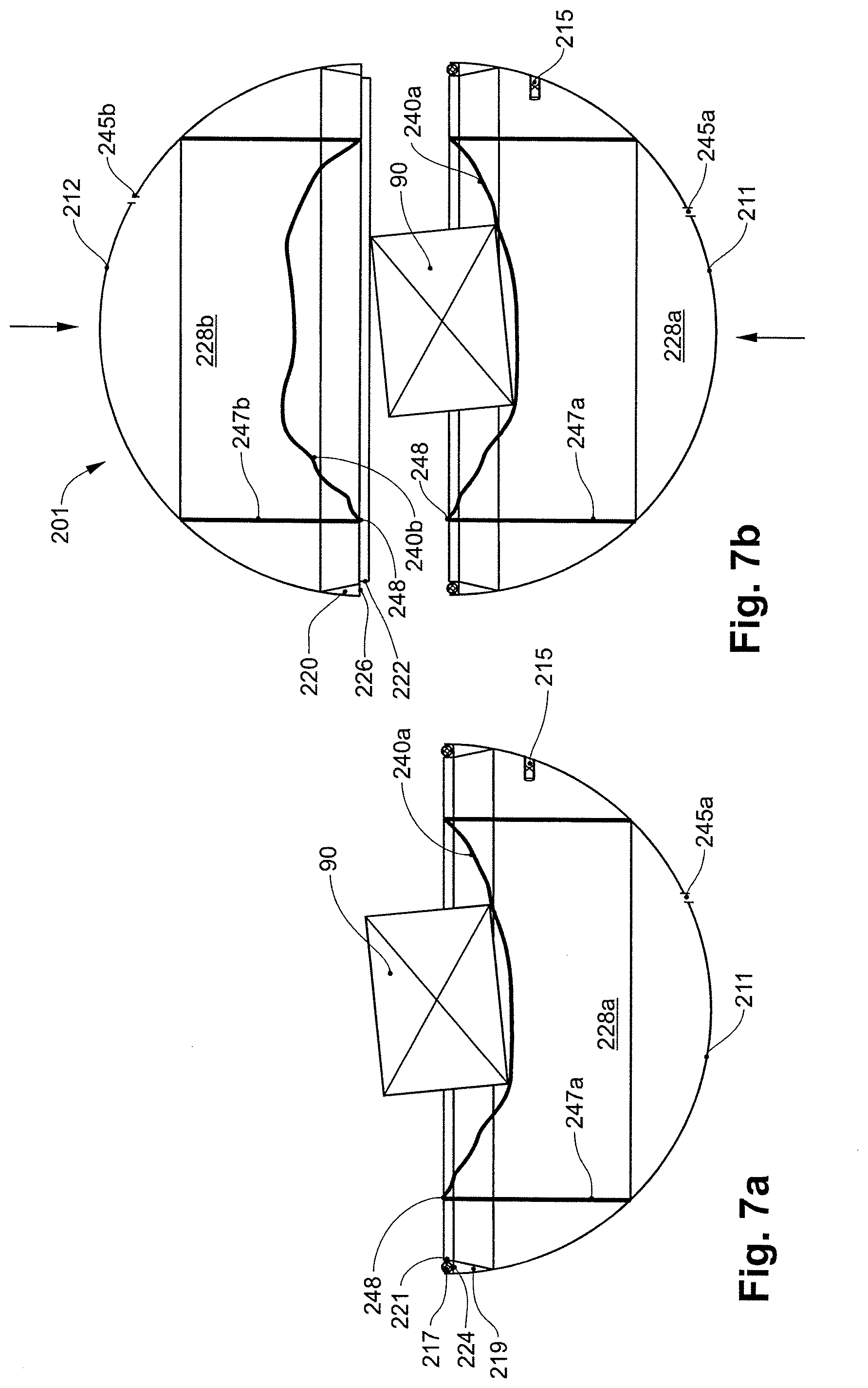
[0064] FIG. 7a schematically shows a cross section of yet another possible embodiment of an advantageous transport unit with a first shell part and a product placed thereon.
[0065] FIG. 7b schematically shows a cross section of the embodiment of FIG. 7a with the first shell part and the second shell part prior to assembly.
[0066] FIG. 7c schematically shows a cross section of the embodiment of FIG. 7a after assembling the shell parts, prior to evacuating the pressure-tightly sealed volume.
[0067] FIG. 7d schematically shows a cross section of the embodiment of FIG. 7a after evacuating the pressure-tightly sealed volume.
[0068] FIG. 8a schematically shows a cross section of yet another possible embodiment of an advantageous transport unit with the shell parts assembled, prior to evacuating the pressure-tightly sealed volume.
[0069] FIG. 8b schematically shows a cross section of the embodiment of FIG. 8a after evacuating the pressure-tightly sealed volume.
[0070] FIG. 8c schematically shows a cross section of the embodiment of FIG. 8a with a detail in the seal area.
[0071] FIG. 9a schematically shows one embodiment variant of an advantageous transport unit in cross section with the shell parts assembled and a product fixed in place.
[0072] FIG. 9b schematically shows the embodiment of FIG. 9a in a top view of the lower shell part and the product laid thereon.
[0073] FIG. 10a schematically shows yet another embodiment variant of an advantageous transport unit in cross section with the shell parts assembled and a product fixed in place.
[0074] FIG. 10b schematically shows the embodiment of FIG. 10a in a top view of the lower shell part and the product laid thereon.
DETAILED DESCRIPTION OF THE INVENTION
[0075] One possible embodiment of an advantageous transport unit 1 is illustrated in FIGS. 1 and 2. The transport unit is made up of two hemispherical shell parts 11, 12 that abut at a parting plane 33 and together form a spherical container shell 10. The two shell parts 11, 12 on the shell inner side have a respective circumferential support structure 19, 20 with a centering ring 21, 22, which in the assembled state (FIG. 2) are in flush alignment one inside the other, and in particular ensure a correctly aligned orientation of the two shell parts. In addition, the centering rings may optionally absorb shear forces that act on the shell parts. The support structures 19, 20 may be designed, for example, as a plurality of inwardly directed ribs distributed along the circumference.
[0076] For the first shell part 11, a groove 24, in which a sealing element in the form of a circumferential sealing ring 17 having an O-shaped cross section is situated, is provided on the support structure 19. The sealing ring may be made of a suitable elastomeric plastic material, for example. For the second shell element 12, a sealing flange 26 is provided on the support structure 20, so that in the assembled state of the transport unit the sealing element 17 is elastically deformed between the groove 24 and the sealing flange 26, thus achieving a fluidic seal between the internal space 28, 29 of the transport unit 1 and the external space 27.
[0077] The shell parts are advantageously manufactured from plastic, in particular a transparent plastic. Shell parts made of metal are also conceivable.
[0078] In the exemplary embodiment of a transport unit shown, a negative pressure is generated in the internal space 28 of the container shell 10, which forms a volume 29 sealed pressure-tight, for a force-fit connection of the two shell parts 11, 12 to form a closed container shell 10. For this purpose, for the first shell part 11 a valve element 15 (only schematically illustrated) is provided via which gas (generally air) may be removed from the volume 29 of the assembled transport unit 1, for example by means of an appropriate pump device. The negative pressure that remains in the inner space of the transport unit 1 after closing the valve results in a closing force Fs that acts on the two shell parts 11, 12 perpendicular to the parting plane 33 and presses the two shell parts 11, 12 together. The shell parts are connected in a force-fit manner along the parting plane 33.
[0079] For example, if a spherical transport unit as discussed above has a radius of r=0.10 m, corresponding to a cross sectional area of approximately A=0.031 m.sup.2, a pressure difference of .DELTA.p=10 kPa (0.1 bar) results in a closing force Fs of approximately 314 N. This corresponds to a weight force of approximately 32 kg. The pressure difference with respect to the external pressure, and thus the closing force, may be set to the desired value by a suitable selection of the internal pressure.
[0080] The partial evacuation of the inner volume 29 sealed pressure-tight thus easily allows generation of a large closing force, which keeps the transport unit securely closed without a complicated mechanism. To reopen the transport unit, it is necessary only to once again eliminate the pressure difference between the inner volume 29 and the external space 27, i.e., atmospheric pressure, for example by opening the valve 15. Alternatively, the two halves may be mechanically separated, for example by providing engagement means on the shell parts that allow the shell elements to be gripped with a suitable tool and pulled or pushed apart with a force greater than the closing force F.sub.S, thus venting the inner volume and eliminating the closing force. In another variant, the sealing device may be manipulated to vent the inner volume.
[0081] Instead of the centering rings of the above-mentioned embodiment of a transport unit, other means for the flush orientation of the two shell elements relative to one another may be used. For example, two or more centering pins or projections may be provided at one or both shell parts that may be brought into operative connection with the corresponding boreholes or recesses in the opposite shell part.
[0082] Instead of an O ring, a sealing ring having a rectangular cross section may be used as the sealing element, or two or more concentrically arranged sealing rings, or a sealing strip, a sealing film, a sealing washer, etc., may be provided.
[0083] FIG. 2 illustrates in a merely schematic manner the product 90 situated in the transport unit. To fix the product within the shell in a form-fit manner, for example adapter devices as known from WO 2014/191107 A1 (FIGS. 1, 2, or 8) may be used. In addition, adapter devices may be used that hold the product and that are supported on the inner side of the container shell, or that are fixed to the container shell.
[0084] For a transport unit as discussed above, the valve is advantageously designed as a one-way valve that allows fluid flow only from the shell interior to the outside. This has the advantage that for a given negative pressure acting on the inner volume 29, the valve is automatically in the closed state. Thus, when the transport unit is sealed, the step of closing the valve is omitted, which simplifies the closing operation.
[0085] One possible embodiment of a suitable valve 15 is illustrated in FIG. 3. A valve opening 15b which on the inner side of the shell adjoins a valve holder 15c integrally formed on the shell is situated in the shell 10. A valve body 15a that separates the inner volume 29 from the external space 27 in a fluidically sealing manner is situated in the interior of the mounting in a form-fit manner. The valve body 15a is designed as a duckbill valve and is advantageously manufactured from a suitable elastomer.
[0086] If the pressure is now reduced in the area of the valve opening 15b, using an external suction device (not illustrated), the duckbill valve opens as soon as the suction pressure is less than the internal pressure. Air is drawn out of the inner volume 29 using the suction device, and the internal pressure drops below atmospheric pressure in the external space 27. After the suction device is removed, the duckbill valve closes due to the pressure difference, which is now negative, between the inner volume 29 and the external space 27, as illustrated in the figure.
[0087] Another possible embodiment of a suitable one-way valve 15 is illustrated in FIG. 4. A cylindrical valve housing 15f having four openings 15b in an outer wall 15j facing the external space 27, and four openings 15g in an inner wall 15h facing the inner volume 29, is fitted in the shell 10. A disk-shaped valve body 15d is situated inside the valve housing 15f. A valve seat in the form of an annular lip 15e is provided on the inner side of the inner wall 15h of the valve housing 15f. In the closed state of the valve 15 illustrated in the figure, the valve body 15d is sealingly pressed against the valve seat 15e by a positive pressure in the external space 27. The valve is closed.
[0088] To maintain a negative pressure difference between the inner volume 29 and the external space 27 (atmospheric pressure), a negative pressure is generated using a suction device on the outer side of the valve, as in the preceding example, and air is withdrawn from the inner volume. The air flows through the openings 15g on the valve body 15d, and through the valve housing and the openings 15b to the outside. Spacers (not illustrated) such as ribs, webs, knobs, projections, or other suitable means prevent the valve body 15d from blocking the openings 15b.
[0089] FIG. 5 shows another embodiment of an advantageous transport unit 101. The spherical container shell 110 once again is made up of two hemispherical shell parts 111, 112 that may be joined along a parting plane 133. The two shell parts are equipped with a valve device 115, 115', respectively. A first shell part 111 has a centering recess 121 with a conical circumferential surface that is supported on a support structure 119 of the shell part. A centering ring 122 with a conical outer circumferential surface is situated on a support structure 120 of the second shell part 112. The circumferential surfaces of the two elements 121, 122 correspond to one another, so that when the two shell parts are joined together they interact as centering means that ensure the flush orientation of the shell parts relative to one another.
[0090] To fix the product 90 to be packaged in the container shell 110, the product 90 is provided with a film wrapping 140, which in the shown example is made up of two superposed plastic films 141a, 141b, between which the product is enclosed in a form-fit manner. The superposed films 141a, 141b define a film wrapping plane 142. In the area around the product the films may be securely welded, adhesively bonded, or joined to one another in some other way, so that a single film layer 140 results. The film wrapping 140 and the product contained therein are subsequently placed between the two shell parts 111, 112 (FIG. 5a), and the shell parts 111, 112 are joined together so that the film wrapping 140 is jammed between the shell parts 111, 112. The film wrapping thus acts as an adapter device for fixing the product within the container shell.
[0091] The film wrapping plane 140 coincides with the parting plane 133 of the shell parts. The film wrapping is jammed between the conical, oppositely situated circumferential surfaces in the area of the conical centering elements 121, 122. The ring-shaped area of the film wrapping between said clamping surfaces acts as a sealing element 117. This results in a fluid-tight closure of the two half-spaces 128a, 128b, and two volumes 129a, 129b sealed pressure-tight are formed (FIG. 5b).
[0092] The two volumes 129a, 129b sealed pressure-tight, the same as for the transport unit in FIGS. 1 and 2, are at least partially evacuated via the two valve devices 115, 115', respectively. The resulting negative pressure difference between the inner volume 129a or 129b and the external space 27 causes the shell parts 111, 112 to be pressed together and securely held together without further mechanical fastening means. A remainder of the film wrapping 140 that protrudes beyond the outer surface may subsequently be cut off and removed so that the rollability of the transport unit 101 is not hindered by the film wrapping 140.
[0093] The internal pressures in the two volumes 129a, 129b are advantageously selected to be equal, so that no mechanical force acts on the film wrapping within the spherical shell 110. This may be achieved, for example, by evacuating both volumes using the same suction system, so that between the two volumes 129a, 129b, for example, pressure compensation is ensured via the piping system of the suction device.
[0094] Alternatively, the pressure in one inner volume 129a, 129b may be set slightly higher than in the other inner volume 129b, 129a, for example with a pressure difference of 100 Pa (1 mbar) or 1000 Pa (10 mbar). The pressure difference keeps the film wrapping 140 in the container shell 110 slightly stretched, thus intensifying the mechanical fixing of the product within the transport unit 101.
[0095] The film wrapping 140 may advantageously be applied to the product, using the method known from WO 2014/191107 A1, in such a way that the center of gravity of the product 90 lies in the film wrapping plane. Since the film wrapping plane coincides with the parting plane 133 of the shell elements, the film wrapping plane extends through the center of the container shell. The center of gravity of the product in relation to the container shell may be shifted by moving the film-wrapped product in the film wrapping plane/parting plane. Ultimately, the center of gravity of the product 90 is advantageously near the geometric center of the container shell 110. This optimizes the rollability of the transport unit, in particular with regard to a smooth rolling movement.
[0096] The conical circumferential surfaces of the centering elements 121, 122 are advantageously made of an elastic material, such as an elastomer, in order to optimize the sealing action between the film wrapping and the circumferential surface.
[0097] FIG. 6 illustrates another embodiment variant of a transport unit 101'. The transport unit 101' essentially corresponds to the transport unit 101 in FIG. 5. However, the second shell part 112 does not have its own valve device. To be able to also partially evacuate the volume 129b that is sealed pressure-tight, at least one opening 144 through which pressure compensation (illustrated as arrows) takes place between the two volumes 129a, 129b is provided in an area of the film wrapping that is subsequently present within the container shell. Thus, a single valve 115 is sufficient for generating a negative pressure in both volumes.
[0098] The film wrapping 140' provided with at least one opening, as discussed above, may also be used with the transport unit 101 from FIG. 5, in such a case the openings being used primarily for compensating for fairly small pressure differences. The evacuation of the internal space may be completed more quickly with two valves, one valve for each inner volume, since the openings 144 allow only a limited flow rate.
[0099] FIG. 7 shows another possible embodiment of an advantageous transport unit 201. The container shell 210 is made up of two hemispherical shell parts 211, 212 that abut at a parting plane 233. Analogously to FIGS. 1 and 2, a support structure 219, a groove 224, a sealing element 217 in the form of a circumferential sealing ring 217 situated in the groove 224, and a centering ring 221 are provided along the surrounding edge of the first shell part 211. The second shell part 212 includes a support structure 220, a sealing flange 226 supported thereon, and a centering ring 222. For the two shell parts 211, 212, a cylindrical partition wall 247a, 247b, respectively, is placed on the inner side of the shell wall in alignment with the axis of symmetry. At their circumferential edges 248 facing the internal space, the two cylindrical partition walls 247a, 247b are closed off with a flexible, gas-tight layer 240a, 240b, for example a flexible and/or elastic plastic film.
[0100] In the assembled state, the cylindrical walls 247a, 247b and flexible layers 240a, 240b divide the internal space of the container shell 210 into a first, essentially cylindrical internal space 228a, a second, essentially cylindrical internal space 228b, and a third, essentially toroidal internal space 228c. The volume region between the two flexible layers 240a, 240b defines a fourth internal space 228d. In the area of the first internal space 228a and the second internal space 228b, a vent opening 245a, 245b, respectively, is provided in the shell which fluidically connects the first internal space 228a and the second internal space 228b to the external space 27. In the assembled state of the transport unit 201 (see FIGS. 7c, 7d), the third internal space 228 [sic; 228c] together with the fourth internal space 228d forms a volume 229 that is sealed pressure-tight. In the area of the third internal space 228c, a valve device 215 is situated in the shell, via which, analogously to the exemplary embodiments discussed above, the pressure in the volume 229 sealed pressure-tight may be reduced with respect to the atmospheric pressure in the external space 27.
[0101] To package a product 90 in the transport unit 201 shown, the product is placed in the area of the flexible layers 240a, 240b between the two shell parts 211, 212. For example, as shown in FIG. 7a, the product 90, for example a cuboidal package with a specified content, may be laid on the flexible layer 240a of a first shell part 211. The second shell part 212 is subsequently joined to the first shell part 211 (FIG. 7b), thus forming a closed container shell 210 with a volume 229 that is sealed pressure-tight (FIG. 7c). The product 90 is now enclosed between the two flexible layers 240a, 240b in a form-fit manner. While the shell 210 is being sealed pressure-tight in the area of the sealing element 217, the two cylindrical partition walls 247a, 247b do not contact one another, or only make contact to the extent that a fluidic connection remains between the third internal space 228c and the fourth internal space 228d, resulting in a combined volume 229 that is sealed pressure-tight. For the force-fit connection of the two shell parts 211, 212, the volume is then partially evacuated via the valve unit 215, for example by means of a suction device (not illustrated), thus generating a negative pressure difference between the inner volume 229 and the external space. Due to the pressure difference, the two shell parts 211, 212 are pressed together and securely remain in the closed state without further mechanical closure elements.
[0102] Since the first internal space 228a and the second internal space 228b are connected to the outside atmosphere via the vent openings 245a, 245b, the flexible layers 240a, 240b collapse while the pressure is being reduced in the volume 229, so that the product 90 is reversibly film-wrapped between the two flexible layers 240a, 240b, i.e., fixed in a form-fit and force-fit manner (FIG. 7d). The cylindrical partition walls 247a, 247b and the flexible layers 240a, 240b thus form an adapter device with which the product 90 is fixed within the container shell 210.
[0103] For the resulting closing force Fs due to the pressure difference .DELTA.p, in the shown embodiment only the ring-shaped cross sectional area of the third, toroidal internal space 228c is relevant, since the flexible layers 240a, 240b essentially completely lie one on top of the other directly or indirectly (via the product 90 enclosed therein), so that no force is transmitted to the shell parts 211, 212. For example, if the spherical transport unit has an outer radius r1=0.10 m and the cylindrical partition walls have an inner radius r2=0.07 m, this corresponds to an active cross sectional area A of approximately 0.016 m.sup.2. By a suitable selection of the internal pressure, the pressure difference relative to the external pressure, and thus relative to the closing force, may be set to the desired value. By a suitable selection of the pressure difference, the closing force may be set to the desired value. A pressure difference of .DELTA.p=10 kPa (0.1 bar) results, for example, in a closing force F.sub.S of approximately 160 N. This corresponds to a weight force of approximately 16 kg.
[0104] To remove the packaged product 90 from the transport unit 201, the volume 229 of the transport unit 201 is once again vented and brought to atmospheric pressure, resulting in elimination of the contact force between the shell parts as well as the form-fit and force-fit fixing between the flexible layers. The shell parts may be separated along the parting plane 233, and the product 90 may be removed.
[0105] FIG. 8 shows yet another possible embodiment of an advantageous transport unit 301. The structural elements, with the exception of the outer seal area between the shell parts, essentially correspond to those in FIG. 7.
[0106] The container shell 310 is made up of two hemispherical shell parts 311, 312 that abut at a parting plane 333 and form a container shell 310. A support structure 319 having a sealing flange 326a is situated along the surrounding edge of the first shell part 311. A sealing ring 317a having a flat, rectangular cross section is situated on the flange 326a. The second shell part 312 includes an analogous support structure 320 with a sealing flange 326b supported thereon. A sealing ring 317b having a flat, rectangular cross section is once again situated on the flange 326b. Magnetic elements 350a, 350b, 350a', 350b', which are situated opposite one another in pairs and ensure an aligned centering of the two shell parts due to the pairwise mutual magnetic attraction, are situated at oppositely facing positions in the support structures 319, 320 of the two shell parts 311, 312. For this purpose, two, advantageously three, four, or more, pairs of magnetic elements are uniformly distributed along the circumference.
[0107] In addition to the centering function, said pairs of magnetic elements also have the secondary purpose of temporarily fixing the two shell elements to one another prior to evacuating the inner volume, which facilitates handling.
[0108] For each of the two shell parts, a cylindrical partition wall 347a, 347b is placed on the inner side of the shell wall. The partition walls are closed off at their circumferential edge with a flexible, gas-tight layer 340a, 340b such as a flexible and/or elastic plastic film.
[0109] The cylindrical partition walls 347a, 347b and flexible layers 340a, 340b, analogously to the exemplary embodiment in FIG. 7, divide the internal space of the container shell 310 into a first internal space 328a, a second internal space 328b, and a third internal space 328c. In the shell, a vent opening 345a, 345b that fluidically connects the first internal space 328a and the second internal space 328b, respectively, to the external space 27 is provided in the area of the first internal space 328a and the second internal space 328b, respectively. In the assembled state of the transport unit 301, the third internal space 328 together with the fourth internal space 328d forms a volume 329, sealed pressure-tight, between the two flexible layers, 340a, 340b. Situated in the shell 310, in the area of the third internal space 328c, is a valve device 315 via which the volume 329 that is sealed pressure-tight may be evacuated and the pressure in said volume 329 may be reduced relative to the atmospheric pressure in the external space 27.
[0110] The assembly and disassembly of the transport unit 301 take place analogously to the embodiment variant in FIG. 7.
[0111] The pairs of magnetic elements may be pairs of permanent magnets in each case, and may advantageously be strong permanent magnets such as neodymium-iron-boron magnets. Alternatively, a pair of magnetic elements may be made up of a permanent magnet and a counterpart made of ferromagnetic iron or the like. It is also possible to use electromagnets, which however, requires the use of an external or internal power source.
[0112] FIG. 9 shows another embodiment variant of an advantageous transport unit 401. The container shell 410 is made up of two hemispherical shell parts 411, 412 that abut a parting plane 433. A support structure 419 having a flange 426a is situated along the surrounding edge of the first shell part 411. The second shell part 412 includes an analogous support structure 420 with a flange 426b supported thereon. Eight pairs of magnetic elements 450a, 450b are situated at oppositely facing positions in the support structures 419, 420 of the two shell parts 411, 412. Due to the pairwise mutual magnetic attraction, these magnetic elements ensure aligned centering of the two shell parts. However, the primary result of the cumulative magnetic attractive force is a closing force that securely keeps the two shell parts together in the assembled state of the container shell 410, without using additional mechanical closure means.
[0113] Closing forces of several hundred newtons may be easily generated with strong permanent magnets. For example, a holding force of 25 N may be achieved with a single individual type N45 neodymium magnet having a diameter of 8 mm and a height of 8 mm. The desired closing force may thus be set via the number, the dimensioning, and the material selection of the magnetic elements.
[0114] The surface of the superposed flanges 426a, 426b in the closed state of the transport unit is advantageously designed in such a way that a preferably high static friction results in order to also obtain high shear forces along the parting plane. Alternatively or additionally, further centering elements such as centering rings analogous to FIG. 1, or conical elements as in FIG. 5, may be provided for absorbing shear forces. Another option is form-fit connections in the parting plane, for example interlocking gear teeth and other structures that prevent the shell elements from shifting relative to one another in the parting plane.
[0115] The advantage of the magnetic closing force used in this embodiment of a transport unit, analogously to the closing force due to the negative pressure in the preceding exemplary embodiments, in which the venting of the inner volume sealed pressure-tight causes the contact pressure to drop quickly to zero, is that the closing force is essentially effective only when the shell elements are joined together. If the shell elements are separated from one another by a targeted external application of force, or the magnetic elements are brought out of their respective range of action by rotation about the normals of the parting plane, the magnetic closing force drops to negligible values very quickly.
[0116] On the inner side of the shell wall, a cylindrical wall 447a, 447b is integrally formed on the two shell parts 411, 412, respectively, and is in turn closed off at the circumferential edge 448 with an elastic layer 440a, 440b, for example an elastic plastic film or an elastic net or mesh. The cylindrical walls and the flexible layers once again divide the internal space of the container shell 410 into a first internal space 428a, a second internal space 428b, a third internal space 428c, and a fourth internal space 428d, which, however, in this embodiment variant do not have a special function with regard to generating the closing force.
[0117] To package a product 90 in the illustrated transport unit 401, the product is placed between the two shell elements 411, 412, and the two shell elements are joined together. The pairs of magnetic elements 450a, 450b ensure the correct orientation, and after joining hold the shell parts together in a force-fit manner. The elastic layers 440a, 440b are elastically stretched when the shell elements 411, 412 are joined together. The resulting tension force fixes the product between the two elastic layers 440a, 440b and within the container shell 410.
[0118] To reopen the transport unit, the magnetic elements are spatially separated from one another by application of force, so that the closing force rapidly drops to zero with increasing distance from the magnetic elements. This may take place, for example, by pushing apart by means of wedge elements which in the parting plane are pressed radially into openings in the shell provided for this purpose. Such an opening operation may be carried out very well automatically.
[0119] In an alternative advantageous variant, the two shell elements are designed in such a way that flat ramps, which engage with one another in flush alignment in the assembled state, are situated along a circle in the parting plane. Optionally, other structures such as a circumferential ridge or two mutually offset rows of ramps may prevent displacement in the parting plane. When the shell parts are rotated relative to one another about the normals of the parting plane, the ramps slide on one another and push the shell elements apart. Such an embodiment has the advantage that a transmission of force results, so that for opening, the force that must be applied is less than the actual closing force perpendicular to the parting plane. At the same time, the type of manipulation of the shell parts necessary for opening the transport unit prevents unintentional opening by externally acting forces, which may be exerted, for example, when the transport unit strikes an obstacle.
[0120] A modification of the preceding embodiment of a transport unit 501 is apparent in FIG. 10, in which the magnetic elements are situated on the cylindrical walls within the container shell.
[0121] Two hemispherical shell parts 511, 512 abut at a parting plane 533 and form a container shell 510. A structure 519 having a circumferential centering groove 521 is situated along the surrounding edge of the first shell part 511. The second shell part 512 includes a support structure 520 with a centering ring 522 that fits the centering groove 521. The centering groove 521 and the centering ring 522 ensure the correct aligned orientation of the shell parts when the transport unit is assembled.
[0122] On the inner side of the shell wall, a cylindrical wall 547a, 547b is integrally formed on the two shell parts 511, 512, respectively. The corresponding opening is closed off at the circumferential edge with an elastic layer 540a, 540b, for example an elastic plastic film or an elastic net or mesh. Four pairs of magnetic elements 551a, 551b are situated at oppositely facing positions on the edge 548 of the two cylindrical walls 547a, 547b of the two shell parts 411, 412. The cumulative magnetic attractive force results in a closing force that securely keeps the two shell parts together in the assembled state of the container shell 510, without using additional mechanical closure means.
[0123] The handling of such a transport unit takes place analogously to that from FIG. 9.
[0124] In yet another embodiment variant of an advantageous transport unit, the above-discussed transport units in FIGS. 1 and 2 or in FIG. 7 are modified in such a way that the circumferential sealing element is designed as a separate sealing ring that has a rectangular cross section and that is positioned between two sealing flanges situated on the respective support structures.
[0125] Said sealing ring is particularly advantageously manufactured from an elastic material and provided with an outwardly protruding tab. To open the transport unit, a user may pull on the tab, resulting in elastic deformation and in particular reduction in the height of the sealing ring, so that the sealing action is eliminated and gas can flow in. The inner volume is vented and the negative pressure is eliminated. The transport unit may now be opened and the packaged goods may be removed.
[0126] Alternatively, such a sealing ring may be made of a moldable plastic compound as used, for example, for the reversible adhesive fastening of suspension hooks on walls. Pulling on the tab deforms this sealing compound in such a way that the sealing action is eliminated. The inner volume is vented, and the transport unit may be opened.
[0127] In yet another embodiment variant of an advantageous transport unit, the above-discussed transport units in FIGS. 1, 2, and 5 through 10 are modified in such a way that the two shell parts are pivotably connected to one another by at least one hinge. Such an embodiment variant has the advantage that the two shell parts cannot be unintentionally separated during processing.
[0128] The above embodiments may also be implemented with shell shapes other than spherical shell shapes, for example other rollable external shapes, but not with nonrollable external shapes such as cuboids, for example.
[0129] The present invention is not to be limited in scope by the specific embodiments described herein. Indeed, various modifications of the present invention, in addition to those de-scribed herein, will be apparent to those skilled in the art from the foregoing description and accompanying drawings. Thus, such modifications are intended to fall within the scope of the appended claims. Additionally, various references are cited throughout the specification, the disclosures of which are each incorporated herein by reference in their entirety.
* * * * *
D00000
D00001
D00002
D00003
D00004
D00005
D00006
D00007
D00008
D00009
D00010
XML
uspto.report is an independent third-party trademark research tool that is not affiliated, endorsed, or sponsored by the United States Patent and Trademark Office (USPTO) or any other governmental organization. The information provided by uspto.report is based on publicly available data at the time of writing and is intended for informational purposes only.
While we strive to provide accurate and up-to-date information, we do not guarantee the accuracy, completeness, reliability, or suitability of the information displayed on this site. The use of this site is at your own risk. Any reliance you place on such information is therefore strictly at your own risk.
All official trademark data, including owner information, should be verified by visiting the official USPTO website at www.uspto.gov. This site is not intended to replace professional legal advice and should not be used as a substitute for consulting with a legal professional who is knowledgeable about trademark law.