Systems And Methods For Particle Focusing In Microchannels
Aguirre; Gerson ; et al.
U.S. patent application number 16/419756 was filed with the patent office on 2019-11-28 for systems and methods for particle focusing in microchannels. The applicant listed for this patent is ABS Global, Inc.. Invention is credited to Gerson Aguirre, Gopakumar Kamalakshakurup, Zheng Xia.
| Application Number | 20190358634 16/419756 |
| Document ID | / |
| Family ID | 68614914 |
| Filed Date | 2019-11-28 |

| United States Patent Application | 20190358634 |
| Kind Code | A1 |
| Aguirre; Gerson ; et al. | November 28, 2019 |
SYSTEMS AND METHODS FOR PARTICLE FOCUSING IN MICROCHANNELS
Abstract
A microfluidic system configured to focus particles suspended in a fluid. One general aspect includes a microfluidic system comprising one or more substrates and a focusing channel formed in the one or more substrates and spanning a length from an inlet to an outlet for receiving a flow of particles suspended in fluid, wherein the particles have a diameter (a) and the focusing channel has a hydraulic diameter (dh).
| Inventors: | Aguirre; Gerson; (Seattle, WA) ; Xia; Zheng; (DeForest, WI) ; Kamalakshakurup; Gopakumar; (DeForest, WI) | ||||||||||
| Applicant: |
|
||||||||||
|---|---|---|---|---|---|---|---|---|---|---|---|
| Family ID: | 68614914 | ||||||||||
| Appl. No.: | 16/419756 | ||||||||||
| Filed: | May 22, 2019 |
Related U.S. Patent Documents
| Application Number | Filing Date | Patent Number | ||
|---|---|---|---|---|
| 62675512 | May 23, 2018 | |||
| Current U.S. Class: | 1/1 |
| Current CPC Class: | G01N 2015/1413 20130101; B01L 3/502761 20130101; B01L 3/502776 20130101; B01L 2300/0883 20130101; B01L 2200/0652 20130101; B01L 2400/086 20130101 |
| International Class: | B01L 3/00 20060101 B01L003/00 |
Claims
1. A microfluidic system for focusing particles suspended in a fluid, comprising: one or more substrates; a focusing channel formed in the one or more substrates and spanning a length from an inlet to an outlet for receiving a flow of particles suspended in fluid, the particles have a diameter (a) and the focusing channel has a hydraulic diameter (Dh), wherein: a. wherein the ratio of the particle diameter to the cross-sectional area of the channel (a/Dh) is between about 0.03 and about 0.06, and/or b. wherein the ratio of curvature (critical parameter; "r") to the hydrodynamic curvature (Dh) defined by the formula 2ra2/Dh3 is less than about 0.03.
2. The microfluidic system of claim 1, wherein the microchannel comprises a repetitively curved segment.
3. The microfluidic system of claim 2, wherein the repetitively curved segment comprises a repeating series of identically-shaped curved sections.
4. A microfluidic system of claim 3, wherein the identically-shaped curved sections are asymmetrically shaped.
5. The microfluidic system of claim 1, wherein the particles comprise bovine sperm.
Description
BACKGROUND OF THE INVENTION
[0001] Flow cytometers function by passing individual particles, such as cells, within a stream of fluid past a detector, which measures certain characteristics of each particle and takes actions based on that evaluation. To do that, the flow cytometer must regulate the flow of the sample so that the particles in the sample move into a substantially single-file particle stream, which enables each particle to be measured individually by the detector.
[0002] One area where flow cytometers have found practical use is in connection with sexing sperm cells, such as bovine sperm, according to sperm cell characteristics for use by the animal reproduction industry to preselect the sex of animal offspring. The most common method for sexing sperm cells is to discriminate based on DNA content. In this context, sperm is combined with an extender and a luminescent dye to stain the DNA inside the sperm cell. The stained sperm cells are then placed in a sample fluid which is introduced into a channel of a microfluidic chip that uses focusing techniques to orient the sperm cell into a substantially single-file stream. After being properly oriented, the sperm cells are illuminated with a light source (e.g., a laser), which excites the luminescent dye in the DNA, giving off a fluorescent luminescence which is detected by a detector (e.g., a photomultiplier tube ("PMT") or an avalanche photodiode (APD)). A sperm containing the X chromosome has more DNA than a Y chromosome-bearing sperm, resulting in the X chromosome-bearing sperm producing more luminescence in response to the detection light source. The detected luminescence is monitored and the system takes selective action, e.g., sorting or killing non-selected sexed sperm with a kill laser, on the individual sperm cells to achieve an end product with the desired characteristics, e.g., a sample with a high concentration of either X or Y chromosome-bearing sperm. For example, if female calves are desired (e.g., for dairy production), then the system is calibrated to collect cells having detected luminescence parameters that are what would be expected of an X chromosome-bearing sperm cell. Alternatively, if male calves are desired (e.g., for beef production), then the system is calibrated to collect cells having detected luminescence parameters that are what would be expected of a Y chromosome-bearing sperm cell.
[0003] Sperm cells may also be distinguished based on DNA content by other methods that do not utilize a DNA dye. For example, U.S. Pat. No. 8,941,062 describes systems and methods of cytometry involving presenting a single sperm cell to at least one laser source configured to deliver light to the sperm cell in order to induce bond vibrations in the sperm cell DNA and detecting the signature of the bond vibrations. Sperm cells may also be analyzed and distinguished based on the presence or absence of cell surface markers or protein, through binding of a fluorescently labeled ligand, such as an antibody. Other methods for discriminating sperm cells may utilize other features of sperm cells, such as mass or volume, to differentiate between those that contain X-chromosomes and those that contain Y-chromosomes. These discrimination and detection methods similarly permit the cells to be selectively differentiated and for the sample to be sexed.
[0004] Sexing techniques include a variety of methods to sort, separate, eliminate, or inactivate unwanted cells. For example, so-called laser kill methods involve exposure of particular cells to a laser with sufficient energy to inactivate the cells. Cells may also be separated into populations through sorting, for example, through droplet formation and deflection as described in U.S. Pat. No. 5,700,692.
[0005] In cell discrimination techniques, including sperm cell sexing applications, proper orientation, ordering, and location of the cells within the microfluidic system is essential to effective operation. For example, positioning and orientation are both essential for being able to effectively detect the difference in fluorescence of X- and Y-chromosome bearing sperm cells stained with a DNA-intercalating dye, as both the positioning of cells within the beam of the detection laser and the orientation of the cells with respect to the detector significantly impact the amount of fluorescence detected. Alterations in the fluorescence, in turn, directly affect the ability to distinguish differences in the fluorescence signal between X-chromosome and Y-chromosome bearing cells. Further, during the sexing process, the various techniques used depend on the ability to accurately locate the cells within the fluid stream. For example, in laser kill sexing, the kill laser is narrowly focused in a particular spot and requires that the cells be positioned properly for the exposure to be effective to be inactivating the cell. Positioning of cells within the flow stream (i.e., up, down, left, and right, with respect to the axis of travel) and ordering (i.e., the distance between cells along the axis of travel) are also important for sorting techniques (i.e., droplet formation and deflection, thermal bubble sorting, etc.). Ordering of cells in a sample flow may be non-deterministic (i.e., follows a Poisson distribution) or deterministic (i.e., spacing). Ordering, therefore, refers to control of cell incidence in the sample flow.
[0006] Hydrodynamic focusing has been utilized to align cells, including sperm cells, in flow cytometry applications for many years, but it may have drawbacks. First, hydrodynamic focusing may involve multiple fluid streams, including one or more sheath fluid streams. Sheath fluid is consumable in the flow cytometric process and can be a significant cost. In addition, hydrodynamic focusing may involve microfluidic chips being designed and produced with complex sample and sheath flow channels, leading to relatively high costs for the microfluidic chips. The number of flow controllers required for each number of fluid inlets may also impact the cost. Further, hydrodynamic focusing relies on a consistent flow rate of the sheath flow, and fluctuations in flow rate, for example, due to a loss of pressure or occlusion of a sheath channel, can have adverse effects on cytometer performance.
[0007] Inertial flow focusing has been utilized for cell types, such as white blood cells and cancer cells. Those cells are significantly larger than sperm cells and are uniformly shaped (i.e., substantially spherical). In contrast, sperm cells are significantly smaller, non-uniform, and have a tail. As a result, the balance of forces acts differently on sperm cells than on other cell types.
SUMMARY OF THE INVENTION
[0008] Certain embodiments of the claimed invention are summarized below. These embodiments are not intended to limit the scope of the claimed invention, but rather serve as brief descriptions of possible forms of the invention. The invention may encompass a variety of forms which differ from these summaries.
[0009] According to an embodiment, particle focusing is achieved using a microchannel, wherein the ratio of the particle diameter (a) to the hydraulic diameter of the channel (Dh), defined by the formula a/Dh, is between about 0.03 and about 0.06, and/or wherein the ratio of curvature (radius "r" or "critical parameter") to the hydraulic diameter of the channel, defined by the formula 2ra2/Dh3, is less than about 0.03.
[0010] As used herein, "focusing" refers to the spatial organization of cells into a desired formation, in particular, into a defined spatial width with reference to an axis along which the cells are moving in a microfluidic channel, and/or relative to a defined point of reference, such as the detection or kill laser focus point or both). In an embodiment, a focused flow of cells will all be within 3-5 times a given cell dimension (i.e., width, height, or length) of the center line of the axis of travel. In other embodiments, a focused flow of cells will all be within 2-3 times the cell dimension and in other embodiments within 1-2 times the cell dimensions.
[0011] Upon entering the microfluidic system, cells are initially unfocused (i.e., not within the desired spatial parameters); various forces can act on the cells within the flow stream to bring them within the desired spatial parameters (i.e., the cells are focused).
[0012] Other aspects will be apparent to one of ordinary skill in the art upon review of the description and exemplary aspects and embodiments that follow.
BRIEF DESCRIPTION OF THE DRAWINGS
[0013] For the purpose of illustrating the disclosure, there are depicted in the drawings certain features of the aspects and embodiments of the disclosure. However, the disclosure is not limited to the precise arrangements and instrumentalities of the aspects depicted in the drawings.
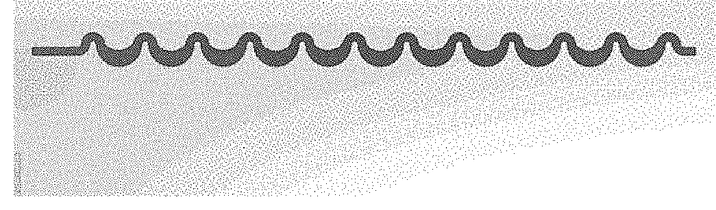
[0014] FIG. 1A shows a repetitively curved portion of a microchannel according to certain aspects of an embodiment of the present disclosure. FIG. 1B shows a modified inertial focusing design according to certain aspects of an embodiment of the present disclosure. FIG. 1C shows a different modified inertial focusing design according to certain aspects of an embodiment of the present disclosure. FIG. 1D shows an inertial focusing design according to certain aspects of an embodiment of the present disclosure.
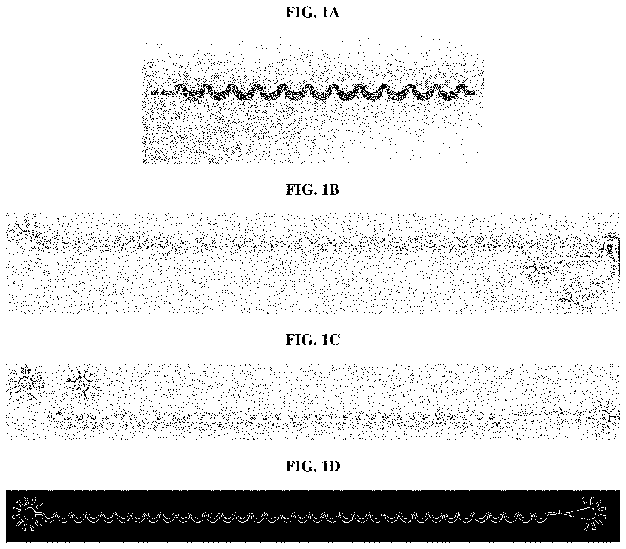
[0015] FIGS. 2A and 2B show enlarged views of a curved segment of an embodiment of the microchannel of FIG. 1.
[0016] FIGS. 3A and 3B show enlarged views of a curved segment of another embodiment of the microchannel of FIG. 1.
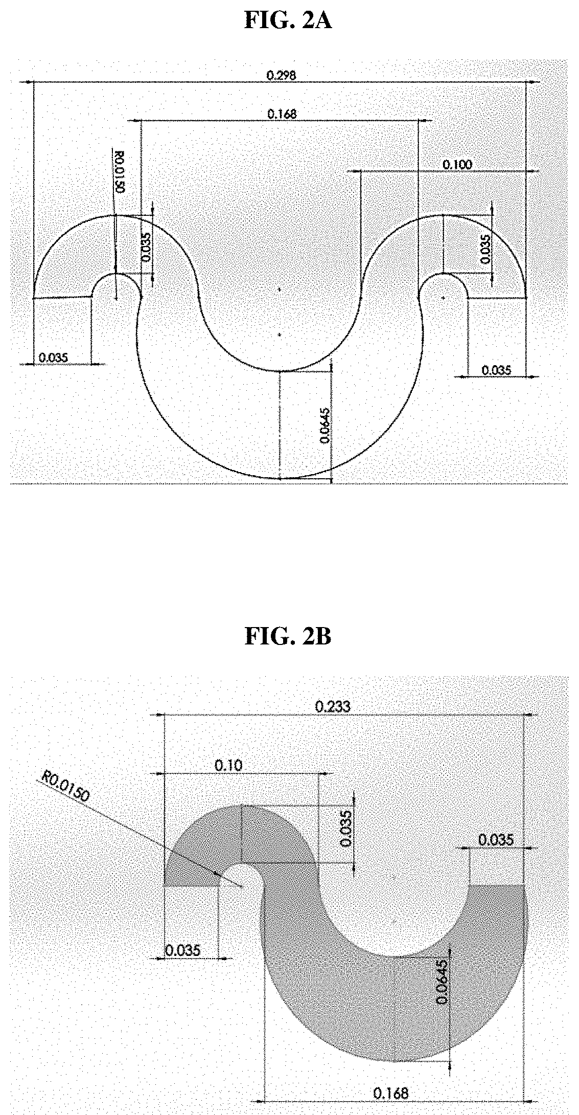
[0017] FIGS. 4A and 4B show the critical parameter or curvature radius "r".
DETAILED DESCRIPTION
[0018] Before continuing to describe various aspects and embodiments in further detail, it is to be understood that this disclosure is not limited to specific compositions or process steps and may vary. As used in this specification and the appended claims, the singular form "a," "an," and "the" include plural referents unless the context clearly dictates otherwise. Ranges expressed herein are inclusive.
[0019] An embodiment of the microfluidic chip may be used in connection with sexing sperm cells such as bovine sperm, for example. In particular, the chip may be used in an apparatus that uses flow cytometry for sexing sperm cells according to DNA characteristics for use by the animal reproduction industry to preselect the sex of animal offspring. Briefly, sperm is combined with an extender and a luminescent dye to stain the DNA inside the sperm cell. The dye-stained sperm cells are then placed in a sample fluid which is introduced into a channel of the microfluidic chip. As the sperm cells are not spherical, the microfluidic chip substantially orients the sperm cells to reduce differences in detecting luminescence that may otherwise be caused by differences in the cell's orientation with respect to the detector.
[0020] The oriented sperm cells are then illuminated with a light source (e.g., detection laser), which excites the luminescent dye in the DNA, giving off a fluorescent luminescence which is detected by a detector (e.g., a photomultiplier tube (PMT) or an avalanche photodiode (APD)). The sperm containing the X chromosome has more DNA than the Y chromosome-bearing sperm, resulting in the X chromosome-bearing sperm producing more luminescence in response to the original illumination. The difference in total DNA content varies by species; for example in Bos taurus, the X chromosome has approximately 3.8% more DNA than the Y chromosome, which results in approximately a 3.8% difference in fluorescence.
[0021] In order to determine which cells to kill, an output signal of the detector representing the amplitude of detected luminescence is monitored. When the detected luminescence value exceeds a set threshold value, an event is considered to have begun. The luminescence value is monitored, and when an inflection point or "peak" is detected, the peak is considered to be the center of the cell, and the peak luminescence value is considered the luminescence value for that cell. If more than one peak is detected in a single event, the peak with the greatest amplitude is considered to be the center of the cell and the peak luminescence value is considered to be the luminescence value for that cell and the other peaks are disregarded.
[0022] The luminescence value for each sperm cell is compared to a gate, which has been previously defined, to determine whether the cell displays the desired luminescence. For example, if female calves are desired (e.g., for dairy production), then the gate is selected to include cells having detected luminescence parameters that are what would be expected of an X chromosome-bearing sperm cell. Alternatively, if male calves are desired (e.g., for beef production), then the gate is selected to include cells having detected luminescence parameters that are what would be expected of a Y chromosome-bearing sperm cell.
[0023] After passing through the detection laser and having their luminescence detected, the stained sperm cells, still in the stream, then pass into the kill zone. A second light source, e.g., the kill laser, is selectively activated to kill cells that fall outside of the selected gate as they pass through the kill zone.
[0024] In other embodiments, particle focusing according to the present invention can be utilized to distinguished sperm cells based on DNA content by methods that do not utilize a DNA dye. For example, U.S. Pat. No. 8,941,062 describes systems and methods of cytometry involving presenting a single sperm cell to at least one laser source configured to deliver light to the sperm cell in order to induce bond vibrations in the sperm cell DNA and detecting the signature of the bond vibrations. In other embodiments, sperm cells may be analyzed and distinguished based on the presence or absence of cell surface markers or protein, through binding of a fluorescently labeled ligand, such as an antibody. Other methods for discriminating sperm cells may utilize other features of sperm cells, such as mass or volume, to differentiate between those that contain X-chromosomes and those that contain Y-chromosomes. These discrimination and detection methods similarly permit the cells to be selectively differentiated and for the sample to be sexed. In further embodiments, sperm cells may be differentiated based on characteristics other than sex. For example, sperm cells may be differentiated on the basis of the presence or absence of a genetic marker or combination of markers, or cell surface protein.
[0025] In other embodiments, particle focusing as described herein may be used for semen sexing techniques to sort, separate, eliminate, or inactivate unwanted cells. For example, so-called laser kill methods involve exposure of particular cells to a laser with sufficient energy to inactivate the cells. Cells may also be separated into populations through sorting, for example, through droplet formation and deflection as described in U.S. Pat. No. 5,700,692. Other sorting techniques for use in the present invention include, for example, bubble sort, acoustic, photonic pressure, holographic laser steering, and optical trapping.
[0026] The microfluidic chip according to the present design uses a repetitively curved microchannel for ordering and focusing particles in sample fluid mixture. The chip may be composed of one or more substrates in which the channel, or a portion of the channel, is formed. The substrate may be composed of one or more layers. The channel is a three-dimensional structure within the assembled one or more layers of the one or more substrates. In one embodiment, the chip may include two layers, a bottom layer and a top layer, that are stacked together to form the chip. In an embodiment, a repetitively curved portion of the microchannel is formed entirely on the bottom layer, while inlets and outlets to the microchannel may be formed on either or both chip layers. In other embodiments, the microchannel may be formed in two or more layers of a substrate, or multiple substrates. The repetitively curved portion consists of a repeating series of identically-shaped turns as is illustrated in FIG. 1
[0027] In use, a sample fluid is introduced into the microchannel through a sample inlet. In the context of bovine semen, the sample includes an ejaculate and a buffer. Upon entering the microchannel, the particles are randomly dispersed within the sample fluid. As the sample flows through, the microchannel of the particles are longitudinally ordered such that, upon exiting the curved portion, the particles are aligned longitudinally in a row. The microchannel may include horizontal/lateral and/or vertical tapering downstream of the curved portion to provide additional focusing of the particles before the fluid moves through a detection region (not shown).
[0028] FIGS. 2A and 2B are enlarged views of a curved segment of an embodiment of the microchannel of FIG. 1, FIGS. 3A and 3B are enlarged views of another embodiment of the microchannel of FIG. 1.
[0029] The channels depicted above which permit only a single focusing position due to the regulating effect of Dean flows comprise 1.5 turns (FIG. 2A and FIG. 3A) or a single turn (FIG. 2B and FIG. 3B). Referring to FIGS. 2B and 3B, each turn includes a smaller region; the critical parameter is indicated (0.015 mm). In both FIGS. 2 and 3, each turn also includes a larger region (i.e., the lower portion of the turn). The smaller region and larger region are staggered. Together, one smaller region and one larger region constitute a single turn of the microfluidic channel. The turns depicted in FIGS. 2 and 3 are asymmetric, in that, the smaller regions and larger regions are different, and the overall turn is therefore not internally symmetric. In other embodiments, the turn may be symmetric, wherein the left and right sides (i.e., the upper and lower portions of the turn) have the same geometries. In other embodiments, the turns within a focusing channel may include one or more symmetric turns, one or more asymmetric turns, or combinations thereof. In further embodiments, the focusing channels may further include other hydraulic mechanisms to effect the positioning, orientation, and/or ordering of particles within the sample flow.
[0030] FIGS. 4A and 4B illustrate how to measure the critical parameter "r".
[0031] As shown in FIG. 4A, the cross-sectional area is determined by the height (H) and width (W) of the microchannel at the smaller region of a turn. FIG. 4B shows the determination of the radius of the smaller region of a turn.
[0032] According to an aspect, particle focusing is achieved using a repetitively curved microchannel:
[0033] wherein the ratio of the particle diameter (a) to the hydraulic diameter of the channel (D.sub.h), defined by the formula a/D.sub.h is between about 0.03 and about 0.06, and/or
[0034] wherein the ratio of curvature (radius "r" or "critical parameter") to the hydraulic diameter of the channel) defined by the formula 2ra.sup.2/D.sub.h.sup.3 is less than about 0.03.
[0035] In an another aspect, the particle may be bovine sperm cells. Bovine sperm cells are irregularly shaped and sperm cells are smaller, non-uniform (.about.3 .mu.m thick.times.5 .mu.m wide.times.10 .mu.m long) and have a tail. In this context, the diameter of the cell is considered to be on the order of about 3 .mu.m to about 5 .mu.m. Substantial particle focusing of bovine sperm cells is observed when the microfluidic channel geometries meet one or both of the above conditions. However, if the physical geometries fall outside these ranges, for example, if a/D.sub.h is greater than about 0.06 or less than about 0.03, bovine sperm cells do not focus.
[0036] Any number of microfluidic system configurations can be designed to achieve certain specific results and/or properties associated with particle focusing within the various channel geometries. In the examples below, certain properties associated with the systems described herein will now be discussed in more detail. While certain experimental conditions may be discussed in reference to certain properties or parameters, it is to be understood that the properties and parameters are widely applicable to any of the channel geometries.
Example 1
[0037] In one aspect, the inertial focusing design (FIG. 1D) was tested in both polydimethylsiloxane (PDMS) and glass at 4 different flow rates. Measurements were taken of core stream width, flat percent, and edge-on percentage, and are shown in Table 1. Figures are shown for PDMS, and where measurements differed when taken in glass chips are shown in parentheses.
[0038] Core stream width (e.g., W_68, W_95, W_100) is the measured width of a certain percentage of the core stream, as measured using images taken by a stroboscope of the sample flowing through the microfluidic chip. For instance, W_68 is the measured width of the 68% of the core stream.
[0039] Flat percent, which is measured on a stroboscope, is the measurement of cells that are oriented with the broadest cross-section parallel to the top of the channel and therefore also perpendicular to the detector and ablation laser beam paths.
[0040] Edge-on percentage, which is measured on a stroboscope, is the measurement of cells with the narrowest cross-section perpendicular to the top of the channel, and therefore parallel to the laser beam paths.
TABLE-US-00001 TABLE 1 Flow rate 68% core width 95% core width 100% core width Flat % Edge-on % 250 .mu.L/min 6-8 .mu.m 12-16 .mu.m 24-30 .mu.m 37-50% (53-68%) 23-29% (7-13%) 300 .mu.L/min 4.5-7.5 .mu.m 9-14 .mu.m 13-33 .mu.m 42-50% (58-67%) 22-27% (5-7%) 350 .mu.L/min 5-7 .mu.m 10-12.5 .mu.m 14-28 .mu.m 45-62% (52-68%) 15-21% (6-9%) 400 .mu.L/min 5-10 .mu.m 12-20 .mu.m 15-31 .mu.m 42-47% (43-68%) 22-24% (7-8%) (10-12 .mu.m) (18-21 .mu.m)
Example 2
[0041] In another aspect, a modified inertial focusing design (FIG. 1C) was tested. The modified design incorporated an upstream element that includes a curvature in the channel in combination with on-chip dilution to achieve sample focusing in the Z dimension (i.e., top-to-bottom, relative to the direction of travel). The parameters for the curvature of this upstream element were 200 .mu.m radius and 100 .mu.m width (R200W100), 300 .mu.m radius and 100 .mu.m width (R300W75), and 500 .mu.m radius and 100 .mu.m width (R500W100). Dilution was tested a 5%, 10%, 12.5%, and 20% dilution. The inertial focusing portion of the modified design is identical to the inertial focusing design tested in Example 1 and measurements reported in Table 2 include core stream width, flat percent, and edge-on percentage.
TABLE-US-00002 TABLE 2 68% core width 95% core width 100% core width Flat % Edge-on % Curvature 5/10/12.5/20% 5/10/12.5/20% 5/10/12.5/20% 5/10/12.5/20% 5/10/12.5/20% dimensions dilution (ave.) dilution dilution dilution dilution R200W100 3.9/4.3/3.9/4.0 .mu.m 7.7/8.5/7.9/8.1 .mu.m 13.3/14.1/14.0/13.6 .mu.m 53/53/51/47% 11/16/15/19% (4.0) (8.0) (13.8) (51%) (15%) R300W75 --/3.6/3.8/4.0 .mu.m --/7.1/7.5/8 --/10.1/12.4/14.1 .mu.m --/58/54/52% --/10/9/7% (3.8) (7.5) (12.2) (54%) (8%) R500W100 4.2/3.5/6.3/4.8 .mu.m 8.4/7.0/12.5/9.5 .mu.m 18.3/7.8/16.4/12.0 65/57/58/62% 11/8/11/13% (4.7) (9.4) (13.6) (60%) (11%)
Example 3
[0042] In another aspect, the different modified design was tested, which incorporated a downstream element that includes a curvature in the channel without any on-chip dilution (FIG. 1B). In another aspect, the secondary region downstream of the inertial focusing channel in this design included a secondary input to potentially adjust the entry point of the cells into the curved section of the drifting element, although this element was not utilized during testing. The data in Table 3 provides the same type of results obtained for the modified and unmodified inertial focusing designs discussed in the previous examples. Measurements were taken using a flow rate of 300 .mu.l/min.
TABLE-US-00003 TABLE 3 68% core 95% core 100% core width width width Flat % Edge-on % 8 .mu.m 16 .mu.m 20 .mu.m 50% 11%
[0043] While illustrative embodiments have been illustrated and described, it will be appreciated that various changes can be made therein without departing from the spirit and scope of the invention.
* * * * *
D00000
D00001
D00002
D00003
D00004
XML
uspto.report is an independent third-party trademark research tool that is not affiliated, endorsed, or sponsored by the United States Patent and Trademark Office (USPTO) or any other governmental organization. The information provided by uspto.report is based on publicly available data at the time of writing and is intended for informational purposes only.
While we strive to provide accurate and up-to-date information, we do not guarantee the accuracy, completeness, reliability, or suitability of the information displayed on this site. The use of this site is at your own risk. Any reliance you place on such information is therefore strictly at your own risk.
All official trademark data, including owner information, should be verified by visiting the official USPTO website at www.uspto.gov. This site is not intended to replace professional legal advice and should not be used as a substitute for consulting with a legal professional who is knowledgeable about trademark law.