Permeate Flow Paterns
Roderick; Kevin ; et al.
U.S. patent application number 16/332767 was filed with the patent office on 2019-11-28 for permeate flow paterns. The applicant listed for this patent is Aqua Membranes Inc.. Invention is credited to Rodney Herrington, Kevin Roderick, Kendall Weingardt.
| Application Number | 20190358590 16/332767 |
| Document ID | / |
| Family ID | 61691134 |
| Filed Date | 2019-11-28 |


| United States Patent Application | 20190358590 |
| Kind Code | A1 |
| Roderick; Kevin ; et al. | November 28, 2019 |
PERMEATE FLOW PATERNS
Abstract
Embodiments of the present invention provide the integration of arbitrary flow directing patterns, deposited or integrated on or into the porous permeate spacer in a spiral-wound membrane separation element.
| Inventors: | Roderick; Kevin; (Albuquerque, NM) ; Herrington; Rodney; (Albuquerque, NM) ; Weingardt; Kendall; (Albuquerque, NM) | ||||||||||
| Applicant: |
|
||||||||||
|---|---|---|---|---|---|---|---|---|---|---|---|
| Family ID: | 61691134 | ||||||||||
| Appl. No.: | 16/332767 | ||||||||||
| Filed: | September 18, 2017 | ||||||||||
| PCT Filed: | September 18, 2017 | ||||||||||
| PCT NO: | PCT/US17/52116 | ||||||||||
| 371 Date: | March 12, 2019 |
Related U.S. Patent Documents
| Application Number | Filing Date | Patent Number | ||
|---|---|---|---|---|
| 62397142 | Sep 20, 2016 | |||
| Current U.S. Class: | 1/1 |
| Current CPC Class: | B32B 2250/20 20130101; B32B 5/028 20130101; B32B 2255/26 20130101; B32B 1/08 20130101; B32B 7/12 20130101; B32B 2250/02 20130101; B32B 9/005 20130101; B32B 5/14 20130101; B01D 63/10 20130101; B01D 2313/146 20130101; B32B 27/12 20130101; B32B 2597/00 20130101; B32B 2255/02 20130101; B32B 7/14 20130101; B32B 5/26 20130101; B32B 9/047 20130101; B32B 15/14 20130101; B01D 61/025 20130101 |
| International Class: | B01D 63/10 20060101 B01D063/10; B01D 61/02 20060101 B01D061/02 |
Claims
1. A permeate spacer configured for use in a reverse osmosis filter, comprising: a first sheet of mesh-type material having first and second opposing faces separated by a thickness and extending for a length in a length direction and a width in a width direction; wherein the first sheet has a mesh permeability; and one or more features having a feature permeability, less than the mesh permeability, wherein the one or more features are disposed within the mesh-type material and extend from the first face to the second face, and configured such that, when in use in a reverse osmosis filter, the one or more features define one or more fluid flow channels within the first sheet.
2. A permeate spacer as in claim 1, configured for use in a spiral wound reverse osmosis filter with the sheet spirally wound along its length, wherein the one or more features define one or more fluid flow channels extending along at least a portion of the length of the first sheet.
3. A permeate spacer as in claim 1, wherein the one or more features define one or more fluid flow channels that begin at a first region of the width, extend along the length for a distance and then return along the length to a second region of the width, where the first and second regions are in substantially the same position relative to the length of the first sheet.
4. A permeate spacer as in claim 3, wherein the first region comprises at least one third of the width of the first sheet at a first end of the length of the first sheet, and the second region comprises at least one third of the width of the first sheet at the first end of the length of the first sheet, wherein the first region is distinct from the second region.
5. A permeate spacer as in claim 1, wherein at least one of the one or more features extends away from the first sheet beyond the first face of the first sheet.
6. A permeate spacer as in claim 5, wherein at least one of the one or more features extends away from the first sheet beyond the first face of the first sheet a distance sufficient to provide feed fluid spacing when the first sheet is spirally wound.
7. A permeate spacer as in claim 5, further comprising a second sheet of permeable mesh-type material, disposed next to the first face of the first sheet such that the one or more features that extend away from the first sheet space the first sheet apart from the second sheet.
8. A permeate spacer as in claim 7, wherein the second sheet comprises one or more features having lower permeability than the permeability of the second sheet, and disposed within the mesh-type material of the second sheet and extending beyond the face of the second sheet that is facing toward the first sheet.
9. A permeate spacer as in claim 7, wherein the second sheet comprises one or more features having lower permeability than the permeability of the second sheet, and disposed within the mesh-type material of the second sheet and extending beyond the face of the second sheet that is facing away from the first sheet.
10. A permeate spacer as in claim 9, wherein at least one of the one or more features in the second sheet extends away from the second sheet a distance sufficient to provide feed fluid spacing when the permeate spacer sheet is spirally wound.
11. A reverse osmosis filter element comprising a permeate spacer as in claim 1 spirally wound about a central fluid flow channel.
12. A method of making a permeate spacer, comprising: supplying a first sheet of permeable mesh-type material; depositing into the first sheet one or more features, wherein the features in the first sheet provide a lesser permeability than the permeability of the first sheet, wherein the features in the first sheet are deposited such that they define fluid flow paths through the first sheet.
13. A method as in claim 12, wherein the features in the first sheet extend through the entire thickness of the first sheet.
14. A method as in claim 12, wherein the features in the first sheet extend through the entire thickness of the first sheet and extend a distance above a face of the first sheet.
15. A method as in claim 12, wherein the features in the first sheet define fluid flow paths that extend along the length of the first sheet, where the length is the dimension of the first sheet that is spirally wound when placed in a reverse osmosis filter.
16. The method of making a permeate spacer of claim 12, further comprising: supplying a second sheet of permeable mesh-type material; depositing into the second sheet one or more features, wherein the features in the second sheet provide a lesser permeability than the permeability of the second sheet, wherein the features in the second sheet are deposited such that they define fluid flow paths through the second sheet; making a permeate spacer by placing the first sheet in contact with the second sheet along faces thereof.
17. The method of making a permeate spacer of claim 16, wherein the features in the first sheet extend through the entire thickness of the first sheet and extend a distance above a first face of the first sheet; and wherein the first sheet is placed in contact with the second sheet with the first face of the first sheet in contact with the second sheet.
18. The method of making a permeate spacer of claim 17, wherein the features in the second sheet extend through the entire thickness of the second sheet and extend a distance above a first face of the second sheet; and wherein the first sheet is placed in contact with the second sheet with the first face of the first sheet in contact with the first face of the second sheet.
19. The method of making a permeate spacer of claim 17, wherein the features in the second sheet extend through the entire thickness of the second sheet and extend a distance above a first face of the second sheet; and wherein the first sheet is placed in contact with the second sheet with the first face of the first sheet not in contact with a first face of the second sheet.
20. The method of making a reverse osmosis filter comprising making a permeate spacer of claim 12, and spirally winding the permeate spacer about a central fluid flow channel.
Description
[0001] The present invention is related to that described in U.S. provisional 61/771,041, filed Feb. 28, 2013, and PCT/IB2014/060705, which are incorporated herein by reference.
BACKGROUND
Field of the Invention
[0002] The subject invention relates to a permeable membrane system utilized for the separation of fluid components, specifically spiral-wound membrane permeable membrane elements.
Description of Related Art
[0003] Spiral-wound membrane filtration elements well known in the art consist of a laminated structure comprised of a membrane sheet sealed to or around a porous permeate spacer which creates a path for removal of the fluid passing through the membrane to a central tube, while this laminated structure is wrapped spirally around the central tube and spaced from itself with a porous feed spacer to allow axial flow of the fluid through the element. While this feed spacer is necessary to maintain open and uniform axial flow between the laminated structure, it is also a source of flow restriction and pressure drop within the axial flow channel and also presents areas of restriction of flow and contact to the membrane that contribute significantly to membrane fouling via biological growth, scale formation, and particle capture. In pressure retarded osmosis (PRO), forward osmosis (FO), and reverse osmosis (RO) applications, flow paths in the feed spaces and the permeate spacer can be beneficial to optimal system operation.
[0004] Improvements to the design of spiral wound elements have been disclosed by Barger et al. and Bradford et al., which replace the feed spacer with islands or protrusions either deposited or embossed directly onto the outside or active surface of the membrane. This configuration is advantageous in that it maintains spacing for axial flow through the element while minimizing obstruction within the flow channel. It also eliminates the porous feed spacer as a separate component, thus simplifying element manufacture. Patent publication number US2016-0008763-A1, incorporated herein by reference, entitled Improved Spiral Wound Element Construction teaches the application of printed patterns on the back side of the active surface of the membrane sheet, or directly on the surface of the permeate spacer.
[0005] The following references, each of which is incorporated herein by reference, can facilitate understanding of the invention: U.S. Pat. Nos. 3,962,096; 4,476,022; 4,756,835; 4,834,881; 4,855,058; 4,902,417; 4,861,487; 6,632,357; and US application 2016-0008763-A1.
DESCRIPTION OF THE INVENTION
[0006] In some spiral-wound membrane separation applications which involve serial flow through the permeate spacer layer of successive elements such as in the PRO patent listed above, it is advantageous to have lower resistance to flow than what is exhibited by traditional woven permeate spacer fabrics, while maintaining other characteristics including resistance to deformation under high external pressure. Additionally, the ability to tailor flow channels of arbitrary shape within the permeate spacer can allow for controllable distribution of flow through the permeate spacer layer. Embodiments of the present invention provide features printed, deposited onto or integrated into the porous permeate spacer to create positive feed channels in the permeate spacer. In additional example embodiments, the material creating the channels can comprise photopolymers, hot melt polyolefins, curable polymers or adhesives, or other materials.
BRIEF DESCRIPTION OF THE DRAWINGS
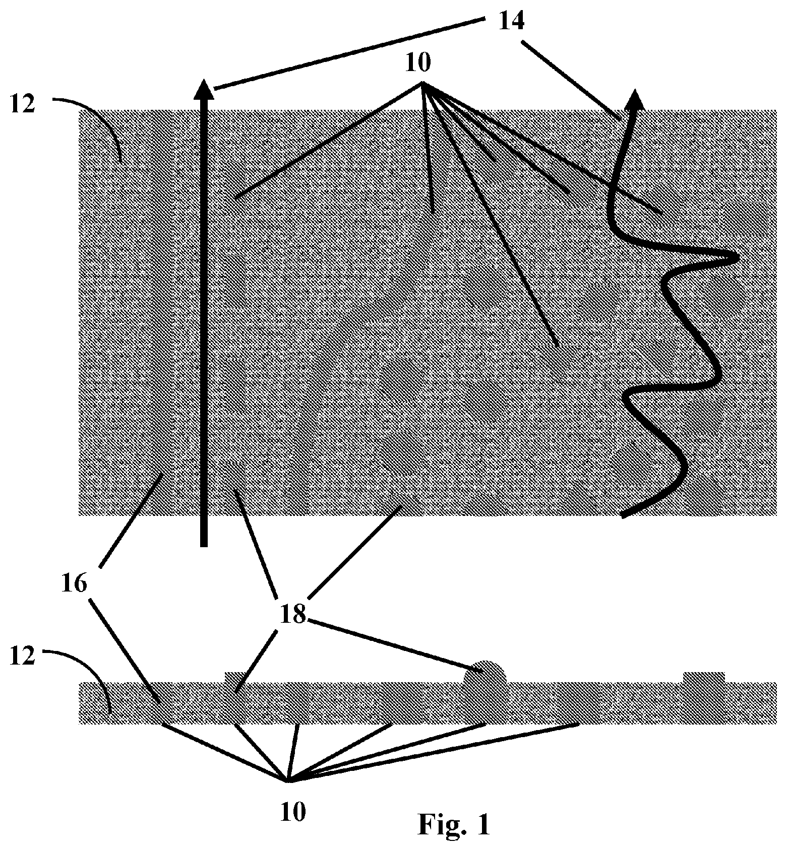
[0007] FIG. 1 shows a top view and a side view of a variety of features printed into the interstitial space of a permeate spacer mesh and of features printed both into and on top of the mesh.
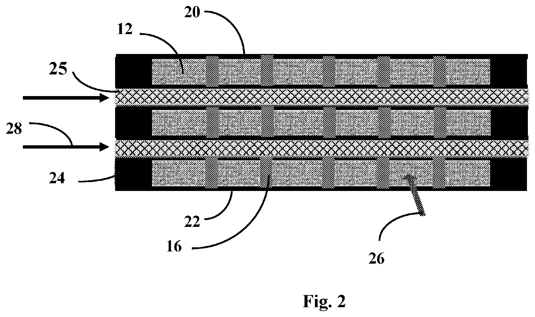
[0008] FIG. 2 is a cross section view of a 3D printed material in the interstitial space of a permeate spacer with conventional feed spacer between the adjacent layers.
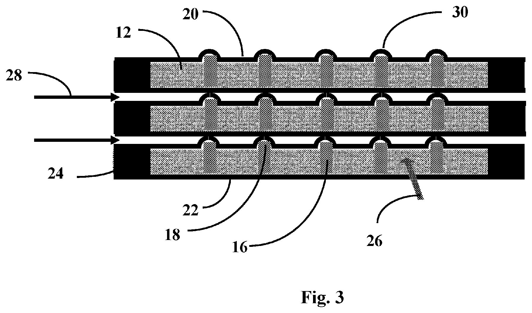
[0009] FIG. 3 is a cross section view of a 3D printed material in the interstitial space and protruding above the permeate spacer which embosses the membrane sheet to form a flow channel in place of the conventional feed spacer.
[0010] FIG. 4 is a cross section view of a 3D printed material in the interstitial space and protruding through the permeate spacer between two sandwiched sheets of feed spacer producing a more free flow path between the adjacent permeate spacer sheets with conventional feed spacer between the adjacent layers.
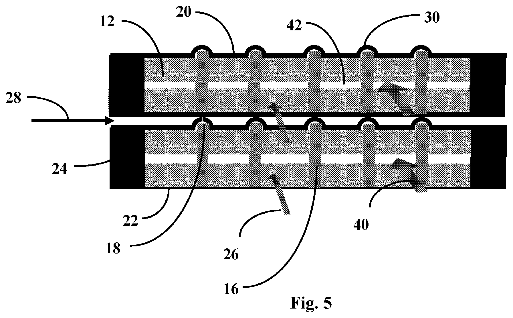
[0011] FIG. 5 is a cross section view of a 3D printed material in the interstitial space and protruding above the permeate spacer between two sandwiched sheets of feed spacer producing a more free flow path between the adjacent permeate spacer sheets. The protrusions adjacent to the membrane sheet emboss the membrane to form a flow channel in place of the conventional feed spacer.
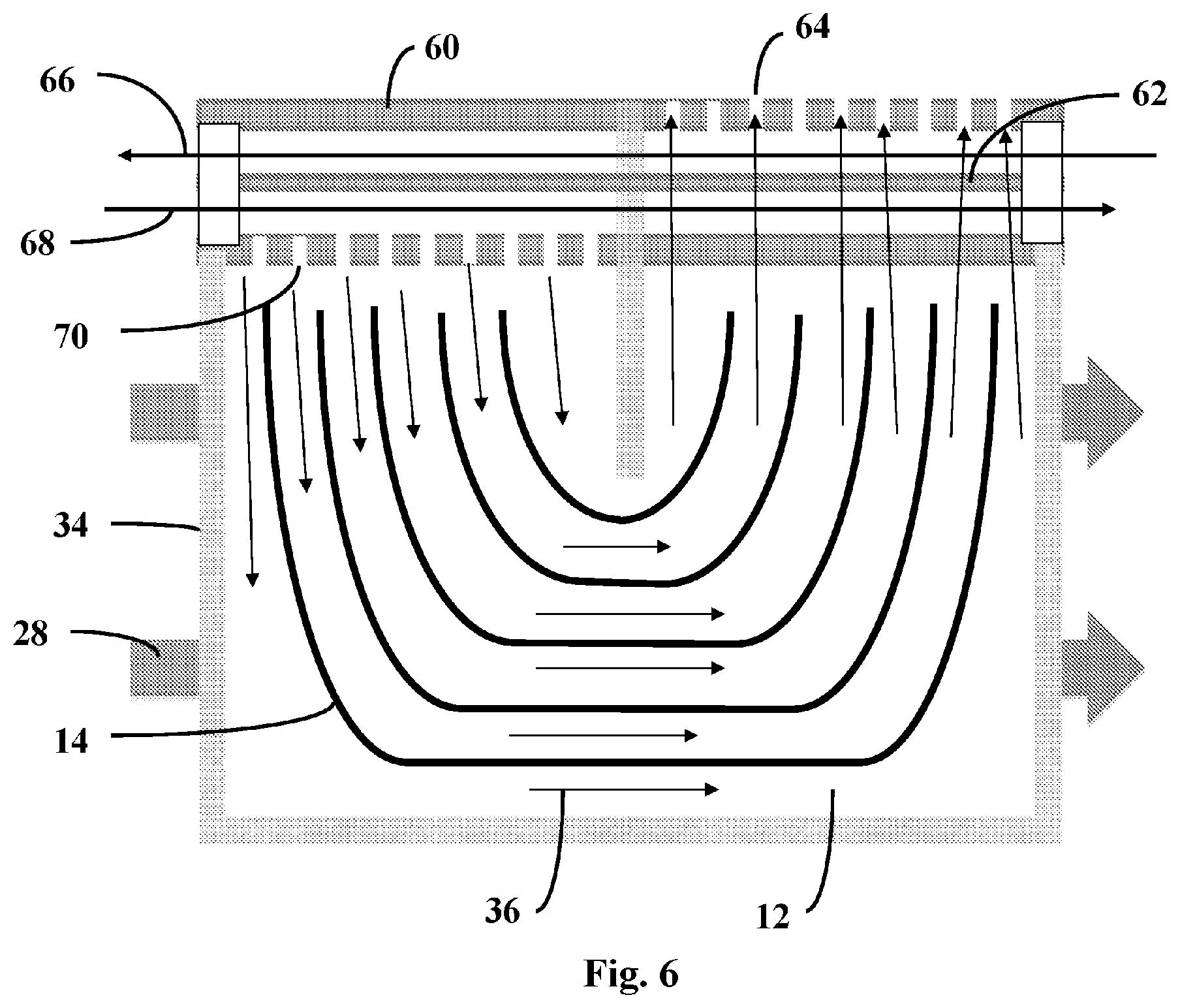
[0012] FIG. 6 is a view of flow control features deposited in to the interstitial spaces of a permeate spacer within a spiral-wound PRO membrane element.
MODES FOR CARRYING OUT THE INVENTION AND INDUSTRIAL APPLICABILITY
[0013] Referring initially to FIG. 1, a single deposited feature or plurality of deposited features 10 such as posts, islands, straight, curved, or angled line segments or continuous lines, or other complex shapes can be deposited into 16 or through and onto the surface of the permeate spacer mesh 12 or printed or otherwise applied into the interstitial spaces of the permeate spacer to create arbitrary flow paths 14 in the permeate spacer, or can be introduced into the permeate spacer during the manufacturing process of the porous permeate spacer layer. The flow channels created in the permeate spacer can also incorporate features protruding above the surface of the permeate spacer to create protrusions on top of the permeate spacer 18. As shown in FIG. 3, such protrusions can be used to act to emboss 30 the surface of the membrane sheet adjacent to the permeate spacer 20 to create a separation between the membrane and spacer with the flat bottom membrane 22 of the adjacent layer. They can be used to direct flow 26 through the permeate carrier mesh and can also be used as a spacer between adjacent stacked sheets of permeate spacer to provide lower resistance to fluid flow 40 through this permeate spacer stacked layer, as shown in FIG. 4. Additionally a thicker two-layer permeate spacer can be produced by stacking one layer with features printed in or through and above the spacer on top of a layer of permeate spacer that has features printed through and above it to create interstitial spaces 42 to allow significantly freer flow through these spaces between the permeate spacer than flow through the permeate spacer mesh itself, as shown in FIG. 4 and FIG. 5.
[0014] Referring to FIG. 6, in some designs of a spiral wound PRO element, a center tube 60 containing a flow separator 62 facilitates liquid flow from the inlet flow 68 through inlet holes 70 into the permeate spacer mesh. The printed features are used to direct and regulate flow through the permeate spacer to optimize flow and mass transfer between the liquid within the permeate spacer and the cross flow feed before the returning permeate flow returns through the outlet holes in the center tube 64 and joins the outlet flow from the center tube 66. In cases where two layers of spacer mesh are used separated by raised features on one layer, the spaces between the layers will create pathways of low resistance to flow, and thus lower pressure drop along the pathways, while still allowing adequate flow through the permeate spacer to the membrane surface to provide adequate mass transfer.
[0015] In an example embodiment the deposited features are used to form arbitrary flow paths through the permeate spacer and a conventional feed spacer mesh is used to separate the adjacent layers within the spiral wound element.
[0016] In an example embodiment the deposited features are used to form arbitrary flow paths through the permeate spacer and the embossed features create spaces in the brine feed channel that otherwise replace feed spacer mesh material that is currently used in the art of fabricating spiral wound membrane elements.
[0017] In an example embodiment two layers of permeate spacer are stacked on top of one another instead of using a single layer with the deposited features forming arbitrary flow paths through the permeate spacer and the protrusions deposited on one or both layers create a space between the layers that creates significantly lower resistance to fluid flow than the permeate spacer material itself while a conventional feed spacer mesh is used to separate the adjacent layers within the spiral wound element.
[0018] In an example embodiment two layers of permeate spacer are stacked on top of one another instead of using a single layer with the deposited features forming arbitrary flow paths through the permeate spacer and the protrusions deposited on one or both layers create a space between the layers that creates significantly lower resistance to fluid flow than the permeate spacer material itself while the embossed features create spaces in the brine feed channel that otherwise replace feed spacer mesh material that is currently used in the art of fabricating spiral wound membrane elements.
[0019] The height and shape of the features can be configured to provide flow paths within the permeate spacer and spacing for embossed or protruding features appropriate to free flow in their respective flow regimes. The features do not need to be entirely solid and can contain some degree of permeability, depending on the printing materials and techniques used. Some amount of permeability can be acceptable because the patterns are made to direct flow but do not need to entirely separate flow. A small amount of flow or diffusion across the patterns that do not substantially affect bulk flow can be acceptable in some applications.
[0020] Those skilled in the art appreciate that the features can be comprised of various materials that are compatible with the separated fluid and the permeate spacer including, but not limited to, thermoplastics, reactive polymers, waxes, or resins. Additionally, materials that are compatible with the separated fluid but not compatible with direct deposition to the permeate spacer, including, but not limited to high-temperature thermoplastics, metals, or ceramics, can be pre-formed, cast, or cut to the proper dimensions and adhered to the surface of the permeate spacer with an adhesive that is compatible with the permeate spacer.
[0021] Those skilled in the art appreciate that the features can be deposited by a variety of techniques. Traditional printing techniques such as offset printing, gravure printing, and screen printing, can be suitable, although there can be thickness and geometry limitations with these deposition techniques. Thicker features can be deposited by microdispensing, inkjet printing, fused deposition, or via application using an adhesive that can include roll transfer of sheet or pick-and-place of individual features.
[0022] The present invention has been described in connection with various example embodiments. It will be understood that the above description is merely illustrative of the applications of the principles of the present invention, the scope of which is to be determined by the claims viewed in light of the specification. Other variants and modifications of the invention will be apparent to those skilled in the art.
* * * * *
D00000
D00001
D00002
D00003
D00004
D00005
D00006
XML
uspto.report is an independent third-party trademark research tool that is not affiliated, endorsed, or sponsored by the United States Patent and Trademark Office (USPTO) or any other governmental organization. The information provided by uspto.report is based on publicly available data at the time of writing and is intended for informational purposes only.
While we strive to provide accurate and up-to-date information, we do not guarantee the accuracy, completeness, reliability, or suitability of the information displayed on this site. The use of this site is at your own risk. Any reliance you place on such information is therefore strictly at your own risk.
All official trademark data, including owner information, should be verified by visiting the official USPTO website at www.uspto.gov. This site is not intended to replace professional legal advice and should not be used as a substitute for consulting with a legal professional who is knowledgeable about trademark law.