Container With Coaster
Zimmer; Matt
U.S. patent application number 16/422114 was filed with the patent office on 2019-11-28 for container with coaster. The applicant listed for this patent is Matt Zimmer. Invention is credited to Matt Zimmer.
| Application Number | 20190357713 16/422114 |
| Document ID | / |
| Family ID | 68615360 |
| Filed Date | 2019-11-28 |


View All Diagrams
| United States Patent Application | 20190357713 |
| Kind Code | A1 |
| Zimmer; Matt | November 28, 2019 |
CONTAINER WITH COASTER
Abstract
An assembly that includes a beverage container having a beverage vessel body that includes: a base, a side wall connected to the base, and a first rim integral with an end of the side wall that is distal to the base. The base includes: a bottom surface, and an arm member extending downward from the side wall. The arm member has an inwardly oriented side, an outwardly oriented side, a surface contacting region, and a detent region defined by the inwardly oriented side. The assembly includes a coaster having a second bottom surface, and a top portion attached to the second bottom surface. The top portion includes a second rim defined by an upwardly projecting ridge, wherein the projecting ridge snaps into the detent region so as to attach the coaster to the beverage container without the need to rotate the beverage container relative to the coaster.
| Inventors: | Zimmer; Matt; (Newprt Beach, CA) | ||||||||||
| Applicant: |
|
||||||||||
|---|---|---|---|---|---|---|---|---|---|---|---|
| Family ID: | 68615360 | ||||||||||
| Appl. No.: | 16/422114 | ||||||||||
| Filed: | May 24, 2019 |
Related U.S. Patent Documents
| Application Number | Filing Date | Patent Number | ||
|---|---|---|---|---|
| 62676648 | May 25, 2018 | |||
| Current U.S. Class: | 1/1 |
| Current CPC Class: | A47G 19/2205 20130101; A47G 23/03 20130101 |
| International Class: | A47G 23/03 20060101 A47G023/03; A47G 19/22 20060101 A47G019/22 |
Claims
1. An assembly, comprising: a beverage container, comprising: a vessel body, comprising: a base; a side wall connected to the base; and a first rim integral with an end of the side wall that is distal to the base, wherein the base comprises: a bottom surface; and an arm member extending downward from the side wall, wherein the arm member comprises: an inwardly oriented side; an outwardly oriented side; a surface contacting region; and a detent region defined by the inwardly oriented side; and a coaster, comprising: a second bottom surface; and a top portion attached to the second bottom surface, comprising: a second rim defined by an upwardly projecting ridge, wherein the projecting ridge snaps into the detent region so as to attach the coaster to the beverage container, wherein attachment of the coaster to the beverage container is accomplished without the need to rotate the beverage container relative to the coaster.
2. The assembly of claim 1, wherein the coaster further comprises an attachment device that engages the second bottom surface.
3. The assembly of claim 2, wherein the attachment device comprises an adhesive layer that engages the second bottom surface.
4. The assembly of claim 3, wherein the attachment device further comprises a second adhesive layer disposed between the first adhesive layer and the second bottom surface.
5. The assembly of claim 3, wherein the coaster further comprises a removable panel covering at least a portion of the adhesive layer.
6. The assembly of claim 2, wherein the attachment device is selected from the group consisting of an adhesive, a hook and loop fastener, and a magnet.
7. The assembly of claim 1, wherein the projecting ridge releasably engages a portion of the detent region.
8. The assembly of claim 1, wherein the beverage container further comprises a lid having a seal region, the seal region removably attached to the first rim.
9. A kit, comprising: a beverage container, comprising: a vessel body, comprising: a base; a side wall connected to the base; and a first rim integral with an end of the side wall that is distal to the base, wherein the base comprises: a bottom surface; and an arm member extending downward from the side wall, wherein the arm member comprises: an inwardly oriented side; an outwardly oriented side; a surface contacting region; and a detent region defined by the inwardly oriented side; and a coaster capable of engaging the beverage container, comprising: a second bottom surface; and a top portion attached to the second bottom surface, comprising: a second rim defined by an upwardly projecting ridge, wherein the projecting ridge is capable of snapping into the detent region so as to attach the coaster to the beverage container, wherein attaching of the coaster to the beverage container is accomplished without the need to rotate the beverage container relative to the coaster; and a package defining a volume of space, wherein the beverage container and the coaster are located within the volume of space and are not engaged to one another while in the volume of space.
10. The kit of claim 9, further comprising an attachment device capable of engaging the second bottom surface.
11. The kit of claim 10, wherein the attachment device comprises an adhesive layer that engages the second bottom surface.
12. The kit of claim 11, wherein the attachment device further comprises a second adhesive layer disposed between the first adhesive layer and the second bottom surface.
13. The kit of claim 11, wherein the coaster further comprises a removable panel covering at least a portion of the adhesive layer.
14. The kit of claim 10, wherein the attachment device is selected from the group consisting of an adhesive, a hook and loop fastener, and a magnet.
15. The kit of claim 9, further comprising a lid capable of removably attaching to the first rim.
16. A method for using a coaster and a beverage container assembly, comprising: attaching a beverage container with a coaster, wherein attachment is accomplished without the need to rotate the beverage container relative to the coaster; and placing the coaster, with the beverage container attached thereto, on a desired surface.
17. The method of claim 16, wherein prior to placing the coaster on the desired surface, an adhesive on the coaster is exposed and the adhesive contacts the desired surface.
18. The method of claim 17, further comprising disengaging the beverage container from the coaster.
19. The method of claim 18, further comprising removing the coaster from the desired surface.
20. The method of claim 18, further comprising re-attaching the beverage container to the coaster.
Description
[0001] This application claims the benefit of priority under 35 U.S.C. .sctn. 119(e)(1) of U.S. Provisional Patent Application Ser. No. 62/676,648, filed May 25, 2018, the entire contents of which are incorporated herein by reference.
FIELD OF INVENTION
[0002] The present invention is directed to a container, such as a beverage container like a wine glass, which can be attached to a coaster that can be attached to a surface. The present invention also relates to assemblies of such containers and coasters in a direct connected, attached configuration, wherein a top portion of the coaster engages a base of the container and a bottom of the coaster is secured to the surface.
BACKGROUND OF THE INVENTION
[0003] Beverages are commonly sold to consumers in containers, such as glass or plastic bottles, aluminum or steel cans, cardboard or plastic cartons, or devices that include bladders containing the beverage. The beverage contained therein can be transferred to a drinking glass composed of a suitable material, including, but not limited to, glass, plastic, or the like. In certain situations, users prefer drinking beverages from individual serving containers, such as cans, juice bottles and the like. However, many consumers prefer drinking certain types of beverages from glasses having wide mouths to enhance the aroma and, therefore, the flavor of the beverage.
[0004] In each of using a drinking glass or individual serving containers, it is common to place the glass or container on a surface, like a coaster or a table. Direct placement on the counter or table can lead to moisture forming on the surface via sweating or spillage from the glass or container. It is well known to use a coaster to prevent moisture forming on the surface by placing the coaster on the surface and placing the glass or container on the coaster. Unfortunately, the coaster can move on the surface when contacted and spillage can occur if a glass or container is on the coaster when the coaster is moved. Spillage can also occur when the glass or container is bumped into while on the coaster.
[0005] It is desirable when using individual serving containers or glasses to secure them in order to reduce the incidence of spillage. It is also desirable to provide a coaster that both engages with the individual serving container or glass and a desired surface.
SUMMARY
[0006] One aspect of the present invention regards an assembly having a beverage container that has a vessel body having a base, a side wall connected to the base, and a first rim integral with an end of the side wall that is distal to the base. The base of the vessel body includes a bottom surface, and an arm member extending downward from the side wall. The arm member includes an inwardly oriented side, an outwardly oriented side, a surface contacting region, and a detent region defined by the inwardly oriented side. The assembly further includes a coaster having a second bottom surface, and a top portion attached to the second bottom surface. The top portion includes a second rim defined by an upwardly projecting ridge, wherein the projecting ridge snaps into the detent region so as to attach the coaster to the beverage container. The attachment of the coaster to the beverage container is accomplished without the need to rotate the beverage container relative to the coaster.
[0007] A second aspect of the present invention regards a kit. The kit includes a beverage container that has a vessel body having a base, a side wall connected to the base, and a first rim integral with an end of the side wall that is distal to the base. The base of the vessel body includes a bottom surface, and an arm member extending downward from the side wall. The arm member includes an inwardly oriented side, an outwardly oriented side, a surface contacting region, and a detent region defined by the inwardly oriented side. The kit further includes a coaster capable of engaging the beverage container that includes a second bottom surface, and a top portion attached to the second bottom surface. The top portion includes a second rim defined by an upwardly projecting ridge, wherein the projecting ridge is capable of snapping into the detent region so as to attach the coaster to the beverage container. The attachment of the coaster to the beverage container can be accomplished without the need to rotate the beverage container relative to the coaster. The kit further includes a package defining a volume of space, wherein the beverage container and the coaster are located within the volume of space and are not engaged to one another while in the volume of space.
[0008] A third aspect of the present invention regards a method for using a beverage container that includes attaching a beverage container with a coaster, wherein attachment is accomplished without the need to rotate the beverage container relative to the coaster. The method further includes placing the coaster, with the beverage container attached thereto, on a desired surface.
BRIEF DESCRIPTION OF THE DRAWINGS
[0009] The various features, advantages and other uses of the present apparatus will become more apparent by referring to the following detailed description and drawing in which:
[0010] FIG. 1 is a perspective view of an embodiment of a known beverage container to be used in accordance with the present invention;
[0011] FIG. 2 is a detail view of a bottom region of the beverage container of FIG. 1;
[0012] FIG. 3 is a top perspective view of an embodiment of a coaster to be used in accordance with the present invention;
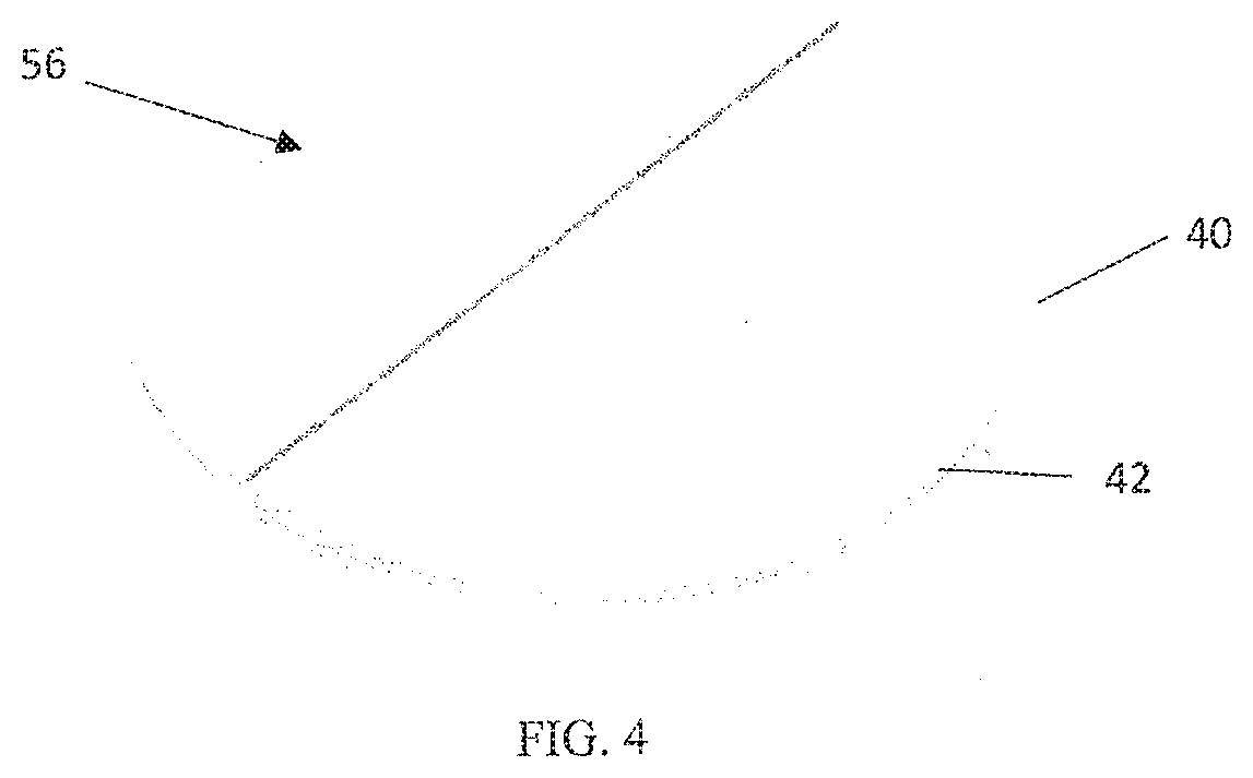
[0013] FIG. 4 is a bottom perspective view of the coaster of FIG. 3;
[0014] FIG. 5 is a side view schematic of the coaster of FIGS. 3 and 4;
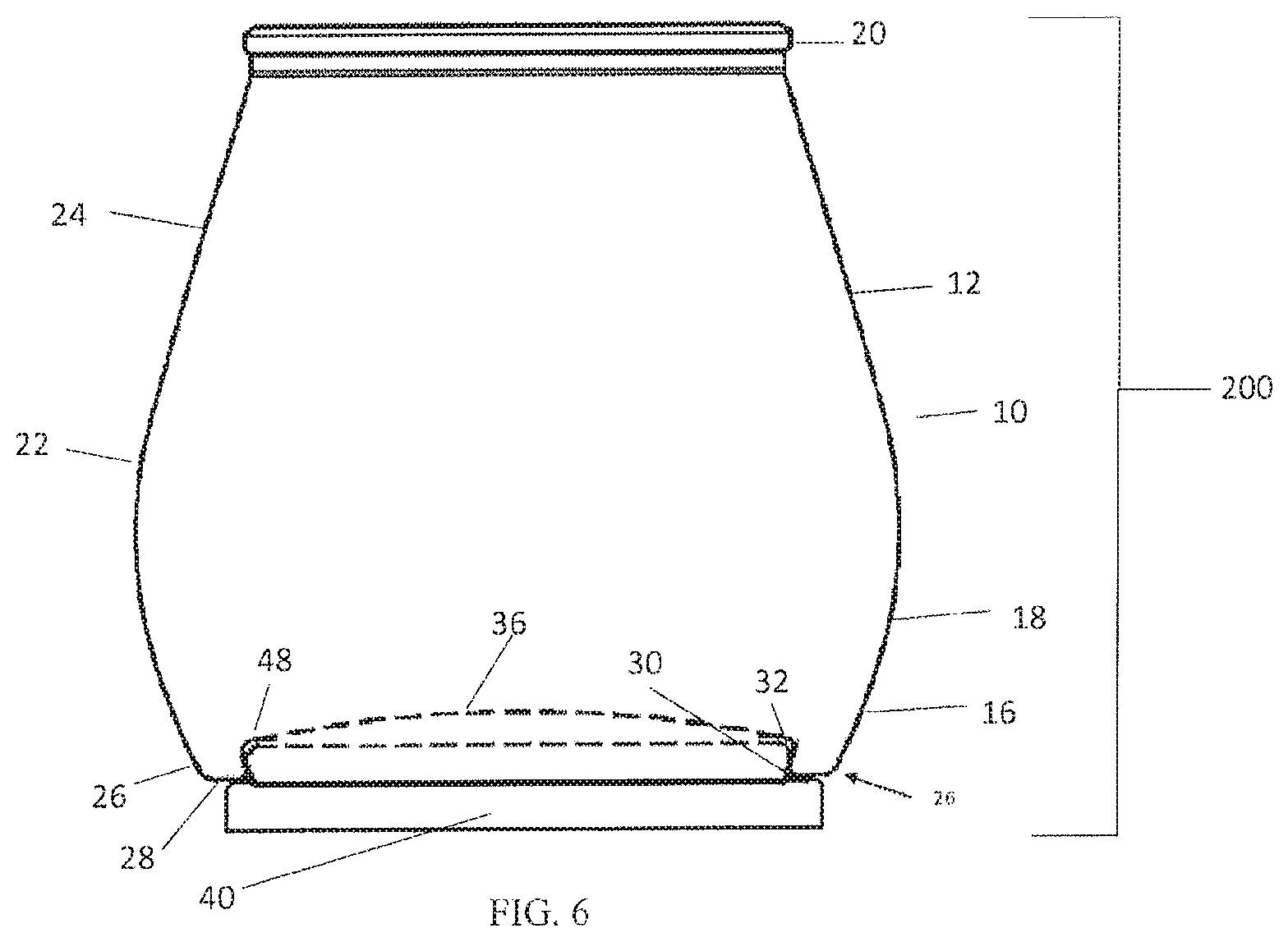
[0015] FIG. 6 is a cross-sectional view of an embodiment of the assembly of the beverage container of FIG. 1 and the coaster of FIG. 3 in accordance with the present invention;
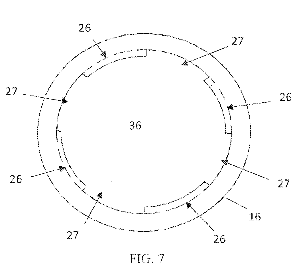
[0016] FIG. 7 is a top view of an embodiment of the base of the beverage container having several arm members;
[0017] FIG. 8 is a side schematic view of an embodiment of a coaster having an attachment device attached;
[0018] FIG. 9 is a side schematic view of an embodiment of a coaster having an attachment device attached;
[0019] FIG. 10 is a side schematic view of an embodiment of a coaster;
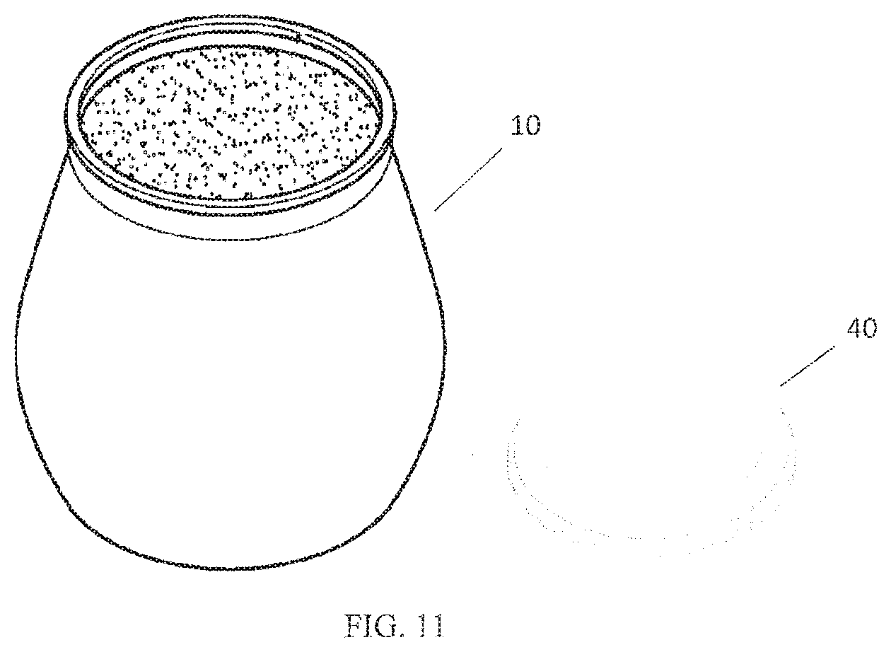
[0020] FIG. 11 is a perspective view of an embodiment of the disassembly of the assembly of FIG. 6 in accordance with the present invention; and
[0021] FIG. 12 is a perspective view of a kit containing a beverage container and a coaster within a package.
DETAILED DESCRIPTION
[0022] As shown in the exemplary drawing figures, and referring particularly to FIG. 1, a container such as a beverage container 10 includes a beverage vessel body 12 and a removable lid 14 sealingly affixed to the beverage vessel body 12. Such a beverage container is described in U.S. Pat. No. 8,807,340, the entire contents of which is incorporated herein by reference. The beverage vessel body 12 can be constructed of any suitable durable material, such as a moldable polymeric material. Where desired or required, the material can be transparent. In specific embodiments, the material employed can be any material that is suitable for use with food stuffs. The material can be one that is dimensionally stable, but can provide minor deformation in specific applications. In applications where the beverage container 10 contains wine, the beverage vessel body 12 can be composed of suitable transparent polymeric material so the user can view the contents of the beverage container 10.
[0023] The removable lid 14 can be made of any suitable material including, but not limited to, foil, plastic and the like. The material employed in the removable lid 14 can be made of a material that is the same or different from the material of the beverage vessel body 12. In some applications, it is contemplated that the material employed in the removable lid 14 will be more deformable than that employed in the beverage vessel body 12 and will be able to conform to suitable dimensional contours by crimping or the like.
[0024] Note that while the beverage container 10 is designed to contain wine, it can contain other liquids, such as teas and juices. Furthermore, the container 10 can house other edible products, such as snacks, cereal, candy, etc. And, of course, the container can house non-edible items, such as toys, office supplies, etc.
[0025] The beverage vessel body 12 includes a base 16 and a side wall 18. The side wall 18 and base 16 define an interior chamber of a specified volume. As such, the side wall 18 will have a suitable height. The side wall 18 extends upward from the base 16 and terminates at a rim 20.
[0026] As shown in FIGS. 1 and 2, the side wall 18 has a curvilinear outer contour that creates at least one bulbous region 22 that extends beyond the perimeter created by the base 16. The side wall 18 has an inwardly tapering region 24 immediately above the bulbous region 22. Tapering region 24 terminates at rim 20, the geometry of which will be described in greater detail subsequently. The side wall 18 curves upward from base 16 to form the bulbous region 22. The side wall 18 then enters a gentle inward curve that proceeds contiguously into tapering region 24. In other embodiments, however, side wall 18 may have other contours, such as a linear outer contour or a concave outer contour.
[0027] The internal volume of the beverage vessel body 12 contained in the internal chamber generally will be suitable to contain a suitable beverage serving. The beverage vessel body 12 will be proportioned in a manner that provides the suitable volume. In certain embodiments, it is contemplated that base 16 will have a cross-sectional diameter between 2 and 4 inches. The inner diameter of rim 20 will be sufficient to permit the beverage to be consumed from the beverage vessel body 12. The maximum diameter of side wall 18 can be between 1/4 inch and 1 inch greater than the diameter of base 16. The total height of the beverage container 10 will be preferably one that approximates the height of a 6 oz. beverage glass in certain applications. Of course, other dimensions are possible for the beverage vessel body 12, base 16, and rim 20 in order to store a desired amount of the contents of the interior chamber defined by the beverage vessel body 12.
[0028] Rim 20 is preferably contiguously joined to the upper region of side wall 18. In certain embodiments, the outer diameter of rim 20 is essentially equal to an inner diameter defined by base 16. The rim 20 also has an upwardly oriented surface that can include at least one upwardly oriented surface or bead projecting therefrom.
[0029] Rim 20 is configured to be placed in mating contact with the removable lid 14 in a manner as described in U.S. Pat. No. 8,807,340 that facilitates establishment of a removed seal. It is contemplated that while removable lid 14 can be used when non-edible items are present within beverage container 10, removable lid 14 would be preferably used when edible items, such as food and wine, are housed within beverage container 10 so as to preserve the freshness of the edible items. Removable lid 14 can contact rim 20 in any suitable manner. In certain embodiments, the lid 14 is configured with a suitable edge region that is affixed to the rim 20 to maintain the beverage inside the beverage vessel body 12. The removable lid 14 can be attached to the rim 20 in any suitable manner including, but not limited to, crimping adhesives and the like. Where an adhesive material is employed, the suitable adhesive material will be one that is suitable for use with food stuffs. Note that an adhesive material is inherently a material that includes an adhesive that is a sticky substance that can adhere or stick to another material. The adhesive material can be present as a layer, bead, or other structure that is interposed between the rim 20 and the interior facing side of removable lid 14. Where desired or required, the interposed adhesive can be positioned such that it contacts all or a portion of the upper surface of rim 20, such as a bead.
[0030] The removable lid 14 can have any suitable configuration to sealingly engage the rim 20 and span the opening defined by the beverage vessel body 12. In various embodiments, the removable lid 14 can be a thin planar member that can conform to and cover the defined opening. For example, the removable lid 14 can be made out of a foil-like material that has a tab that extends beyond the bead so that a user can grasp the tab and remove the lid 14. When in sealing engagement, the removable lid 14 can deflect inward into the opening defined in the beverage vessel body 12. The removable lid 14 can have a suitable peripheral region proximate to its outer edge that can be configured to conform to at least a portion of the rim 20.
[0031] The desired beverage can be sealed in the beverage vessel body 12 by removable lid 14. When the beverage vessel body 12 is composed of a suitable transparent polymeric material, the beverage will be visible through the beverage vessel body 12. As mentioned previously, that besides liquids, the beverage vessel body 12 can contain other types of objects, such as solid foods.
[0032] As mentioned previously, the rim 20 can have any configuration that will facilitate sealing engagement between the lid 14 and the beverage vessel body 12. In one configuration, the rim 20 can include a generally vertical neck portion with a bead present at an end thereof. In another embodiment, the rim 20 can be configured with a plurality of steps positioned on interiorly and exteriorly oriented surfaces relative to a bead. It is contemplated that adhesives or other sealing material can be interposed between the previously mentioned interiorly oriented steps and removable lid 14. Note that an adhesive material is inherently a material that includes an adhesive that is a sticky substance that can adhere or stick to another material. As used herein the term "adhere" is taken to include connection facilitated by direct rim-to-lid adhesion as well as interposition of a suitable adhesive layer between the rim 20 and the lid 14. Where a line of adhesive is used, it is contemplated that the adhesive line can be deployed so as to contact a bead of rim 20 and, if desired, the adhesive can be disposed such that the adhesive contacts multiple planar surfaces defined in the inwardly oriented surface of the rim 20.
[0033] It is also possible to configure removable lid 14 to conform to one or more of the geometric ridges and/or shelves defined in the upper surface of the rim 20. Conformance can be accomplished during manufacture of lid 14 or during attachment of lid 14 to associated rim 20. Conformance fitting may be augmented by adhesives where desired or required.
[0034] Where desired or required, the rim 20 can have suitable outer geometric details, such as various combinations of shoulders and shelves, sufficient to permit contact with lid 14, but small enough to permit an enjoyable drinking experience.
[0035] While an adhesive attachment between the lid 14 and the associated rim 20 has been previously described, other types of attachment are possible. For example, an outer edge of the lid 14 could be crimped like a beer bottle cap so as to engage an exterior side of the rim 20. Another possibility is to slightly melt the top layer of the rim 20 and/or the bottom of the lid 14 prior to placing the lid 14 thereon so that a seal is formed between the lid 14 and rim 20.
[0036] While the previous descriptions regarded the situation where the lid 14 is attached to the rim 20 of the beverage container 10, it is also possible not to use lid 14 in conjunction with the beverage container 10.
[0037] The base 16 of beverage vessel body 12 can be configured to releasably engage with a suitable accessory, like a coaster 40. As shown in FIGS. 2 and 6, the base 16 includes at least one arm member 26 having an outwardly oriented side 28 contiguously connected to the lower region of the side wall 18 at a location on beverage vessel body 12 opposite to the rim 20. The arm member 26 defines an inwardly oriented detent 30 generally opposed to outwardly oriented side 28 that terminates in bottom surface 36 (shown in phantom in FIGS. 2 and 6). The size, number and positioning of arm member(s) 26 is sufficient to releasably engage a rim 48 of the coaster 40, the geometry of which will be subsequently described in greater detail. In this case, a single arm member 26, preferably extends continuously around the entire circumference of base 16 and defines a surface contacting region 34. Of course, having the arm member 26 extend around a portion of the circumference is also possible, as shown in FIG. 7. In the embodiment of FIG. 7, the arm members 26 are the same size and equally spaced from one another by equally spaced gaps 27 schematically. In some embodiments, the geometry of the arm member(s) 26 may include teeth-like members to engage the rim 48. Additionally, or alternatively, the rim 48 may have teeth-like members to engage the arm member(s) 26, the geometry of which will be described in greater detail subsequently.
[0038] The inwardly oriented detent 30 can have any suitable internal wall configuration sufficient to receive and maintain at least a portion of rim 48 of an associated coaster 40 in engaged relationship. In FIGS. 2 and 6, the internal wall of detent 30 has a concave configuration forming a detent region 32 that can releasably engage the corresponding rim 48 of the coaster 40. In FIG. 6, the inner wall of detent 30 contacts a projecting ridge 46 associated with rim 48.
[0039] The arm member 26 can be either of solid or hollow construction depending on the specific application. In FIG. 2, arm member 26 is a continuous solid circular body contiguously positioned relative to side wall 18 and bottom surface 36. Without being bound to any theory, it is believed that the solid continuous arm member 26 provides stability to the associated beverage vessel body 12.
[0040] The bottom surface 36 (shown in phantom in FIGS. 2 and 6) can have any suitable geometric configuration. As shown in FIGS. 2 and 6, the bottom surface 36 has an inwardly curved geometry having a lowest region proximate to arm member 26 and a maximum inwardly oriented point proximate to the radial center of the beverage container 10. The arc defined by curved bottom surface 36 is between 1 degree and 30 degrees from planar.
[0041] Engagement between rim 48 and the arm member 26 generally occurs at a junction point located at a lower portion of detent 32 and projecting ridge 46 of the respective elements as shown in FIG. 6.
[0042] FIG. 3 shows an embodiment of a coaster 40 to be releasably engaged to the beverage container 10. As shown in FIGS. 3 and 4, the coaster 40 includes a bottom surface 42 and a top portion 44. The top portion 44 is configured to releasably engage a suitably configured base 16 of beverage container 10. The coaster 40 can be constructed of any suitable material, such as a suitable moldable polymeric material. In some embodiments, it is contemplated that the coaster 40 be manufactured using a custom injection molding process. Other suitable molding processes may be used as well. Where desired or required, the material can include wood, metal, or any other suitable material for use as a coaster. The material can be one that is dimensionally stable, but can provide minor deformation in specific applications.
[0043] As shown in FIG. 3, the top portion 44 includes an upwardly projecting annular-like ridge 46 extending from the top surface of the coaster 40. The projecting ridge 46 extends radially inward from its perimeter 45 until the ridge drops off to form an indented top surface 47 in the center of the top portion 44. The dotted line in FIG. 5 represents the indentation defining the indented top surface 47. As shown in FIG. 5, the perimeter 45 of the projecting ridge 46 defines the rim 48. In certain embodiments, the projecting ridge 46 has a height approximately between 0.04 inch and 0.08 inch (i.e. 1-2 millimeters) above the indented top surface 47. Nonetheless, the projecting ridge 46 will have sufficient height to mate with the arm member(s) 26 of the base 16, the mating of which will be subsequently described in greater detail. In certain embodiments, the rim 48 can be defined by various combinations of shoulders and shelves. As mentioned earlier, the rim 48 may also include teeth-like members to mate with arm member(s) 26 of the base 16. The teeth-like members may span the entire circumference of the rim 48 or only a portion thereof.
[0044] The coaster 40 will be proportioned such that it forms a suitable surface for the beverage container 10. In certain embodiments, it is contemplated that the overall height of the coaster 40 be between 1/8 inch and 3/16 inch, and the overall diameter of the coaster 40 is preferably 2 inches to 2.5 inches. Nonetheless, the projecting ridge 46 will be sufficient diameter to engage the arm member(s) 26 of base 16. Of course, other dimensions are possibly for the coaster 40 in order to sufficiently support and engage the beverage container 10.
[0045] As shown in FIG. 6, the rim 48 is configured to matingly contact the arm member(s) 26. The rim 48 snaps into the detent region 32 and contacts the surface contacting region 34. Similarly, the arm member 26 snaps into an indentation 49 formed in the rim 48. In other embodiments, the projecting ridge 46 may engage a portion of the detent region 32 and contact a portion of the surface contacting region 34. The rim 48 and the arm member(s) 26 mate in a manner such that rotation of the beverage container 10 with respect to the coaster 40 is unnecessary to secure the beverage container 10. The beverage container 10 is free to rotate in any direction when mated with the coaster 40. In order to disengage the beverage container 10 with the coaster 40, a user must use force sufficient to overcome the contact forces between the arm member(s) 26 and the rim 48. Likewise, to engage the beverage container 10 with the coaster 40, a user must apply a force sufficient to push the rim 48 past the arm member(s) 26 and into the detent region 32.
[0046] Bottom surface 42 is generally planar and can conform to a desired surface, such as a table top or counter. The top portion 44 is attached to the bottom surface 42 such that the top portion 44 extends away from a desired surface.
[0047] As schematically shown in FIGS. 8-10, an attachment device 50 may engage the bottom surface 42 of the coaster 40. The attachment device 50 can secure the coaster 40 to a desired surface, such as the top of a table or a counter. The attachment device 50 defines an adhesive layer 52 that has an upper surface 53 that adhesively engages the bottom surface 42. The adhesive layer 52 adhesively secures the coaster 40 to a desired surface. A lower surface 55 of the adhesive layer 52 sufficiently adheres such that the beverage container 10 can be attached and detached from the coaster 40 without the coaster 40 moving with respect to the desired surface. Note that an adhesive material is inherently a material that includes an adhesive that is a sticky substance that can adhere or stick to another material. There are adhesive materials having varying degrees of adhesive properties such that one adhesive material may be "stickier" or stronger than another adhesive material. In the present disclosure, it is contemplated that the coaster 40 having the adhesive layer 52 disposed thereon is capable of being removed from a first desired surface and reused on a second desired surface, and removed and reused on other surfaces over the life of the adhesive material.
[0048] As shown in the alternative embodiment of FIG. 10, the attachment device 50a includes a second adhesive layer 54 disposed between the adhesive layer 52 and the bottom surface 42. The adhesive layer 52 and the second adhesive layer 54 may have the same or different adhesive properties. As previously mentioned, the adhesive layer 52 and the second adhesive layer 54 may be removed and reused on other surfaces.
[0049] A shown in FIG. 9, the coaster 40 can further include a removable panel structure 56 that covers at least a portion of the adhesive layer 52 of FIG. 8 to protect the adhesive material prior to use. As shown in FIG. 4, removable panel structure 56 includes two half-circle-shaped panels. There are no limits on the size and shape of the panel(s) used to cover the adhesive material. The removable panel structure 56 can be made of any suitable material, such as a flexible polymeric material capable of being peeled away from the adhesive layer 52. Similarly, the removable panel structure 56 can be used to cover adhesive layer 54 of the embodiment of FIG. 10.
[0050] As shown in FIG. 10, an alternative embodiment for the attachment device 50 is an attachment device 50b wherein layer 50a is replaced by a hook and loop fastener 58 that is adhesively adhered to the coaster 40 by layer 52. The hook or loop fastener 58 engages a complementary hook or loop fastener 58 attached to the desired surface. Another possible embodiment is an attachment device 50c wherein layer 50a is replaced by a magnet 60 that is adhesively adhered to the coaster 40 by layer 52. The magnet 60 engages either a complementary magnet attached to the desired surface or a desired surface that is itself magnetic, like some stainless steel tables. The disclosed embodiments do not limit the number or size of the magnet 60 or hook and loop fastener 58 necessary to secure the coaster 40 to a desired surface.
[0051] In other embodiments, the coaster 40 may attach to a desired surface by suction, like a suction cup. It is preferable that the coaster 40 be made from a suitable flexible material and that the bottom surface 42 be concave to enable suction. The coaster 40 will adhere to the desired surface when a sufficient force is applied to the top portion 44--the concave bottom surface 42 will become relatively planar. However, a pocket of air having a lower pressure than the surrounding air pressure will form between the desire surface and the bottom surface 42 creating a suction effect.
[0052] As shown in FIG. 6, when beverage container 10 is attached to coaster 40, they define an assembly 200. As previously mentioned, the beverage container 10 may have a serving of a given beverage located in a sealed chamber defined in the beverage vessel body 12. In the assembly 200, the base 16 of the beverage container 10 can releasably engage the rim 48 of the coaster 40. In addition, note that the beverage container 10 may include a plastic cap to cover the lid 14.
[0053] The present disclosure contemplates a method for using beverage containers and coasters such as those previously described. Without any need to rotate a beverage container 10 relative to a coaster 40, a user can attach the beverage container 10 with the coaster 40 in the manner previously described herein. In certain embodiments, before placing the coaster 40 on a desired surface, like a counter or tabletop, the user may remove the removable panel structure 56 so to expose the adhesive layer 52. Of course, other attachment devices, like those contemplated herein, may require different steps. For example, the hook and loop fastener 58 may require the user to place the hook portion of the hook and loop fastener 58, or vice versa, on the desired surface prior to placing the coaster 40 on the desired surface. The user may then place the coaster 40, with the beverage container 10 attached thereto, on the desired surface.
[0054] Once the coaster 40 is attached to the desired surface, a user may desire to use the beverage container 10 for drinking or eating. The method may further include the user disengaging the container 10 from the coaster 40 to take a drink, for example, while the coaster 40 remains attached to the desired surface. After such use, the beverage container 10 can be re-attached to the coaster 40 in a manner previously disclosed herein. A user may repeatedly detach the beverage container 10 from the coaster 40 and repeatedly re-attach the beverage container 10 to the coaster 40.
[0055] If a user no longer wishes to use the coaster 40 for drinking or eating, the user may remove the coaster 40 from the desired surface, and save for the next time the user wishes to use the beverage container 10 and the coaster 40. Alternatively, if the user wishes to remove the coaster 40 from the desired surface to a second desired surface, for example, from a counter to a coffee table, the user may re-attach the coaster 40 to the second desired surface. It is contemplated that the coaster 40 may be repeatedly attached and removed from any desired surface over the life of the attachment device 50.
[0056] As shown in FIGS. 11 and 12, when a package 310 defining a volume of space contains any number of beverage containers 10 and coasters 40 that are not engaged to one another while within the package 310, they define a kit 300. The beverage container 10 may contain an assortment of various beverages and food stuffs, like different types of wines. The coasters 40 located in package 310 may be an assortment of coasters of various materials, for example. In one embodiment, the package 310 may include an outer covering member. Other non-limiting examples of outer covering include boxes and shrink wrap and the like.
[0057] The kit 300 may further include various attachment devices 50, 50a, 50b, and 50c as previously described herein. For example, a kit may provide a combination of adhesive layers 52, adhesive layer 52 with adhesive layer 54, hook and loop fasteners 58, and/or magnets 60 for use with the coasters 40 contained within package 310. The attachment devices 50, 50a, 50b, and 50c are separate from the coasters 40 within the package 310 and can be attached to the bottom surface 42 of the coaster 40 in a manner previously described herein. The combination of attachment devices 50, 50a, 50b, and 50c is not limited to those found in the present disclosure.
[0058] While the invention has been described in connection with what is presently considered to be the most practical and preferred embodiment, it is to be understood that the invention is not to be limited to the disclosed embodiments but, on the contrary, is intended to cover various modifications and equivalent arrangements included within the spirit and scope of the appended claims, which scope is to be accorded the broadest interpretation so as to encompass all such modifications and equivalent structures as is permitted under the law.
* * * * *
D00000
D00001
D00002
D00003
D00004
D00005
D00006
D00007
D00008
D00009
D00010
D00011
D00012

XML
uspto.report is an independent third-party trademark research tool that is not affiliated, endorsed, or sponsored by the United States Patent and Trademark Office (USPTO) or any other governmental organization. The information provided by uspto.report is based on publicly available data at the time of writing and is intended for informational purposes only.
While we strive to provide accurate and up-to-date information, we do not guarantee the accuracy, completeness, reliability, or suitability of the information displayed on this site. The use of this site is at your own risk. Any reliance you place on such information is therefore strictly at your own risk.
All official trademark data, including owner information, should be verified by visiting the official USPTO website at www.uspto.gov. This site is not intended to replace professional legal advice and should not be used as a substitute for consulting with a legal professional who is knowledgeable about trademark law.