Application Of Cosmetic Product, Such As Mascara
Limongi; Michel
U.S. patent application number 16/472647 was filed with the patent office on 2019-11-28 for application of cosmetic product, such as mascara. This patent application is currently assigned to Texen Services. The applicant listed for this patent is Texen Services. Invention is credited to Michel Limongi.
| Application Number | 20190357659 16/472647 |
| Document ID | / |
| Family ID | 58401791 |
| Filed Date | 2019-11-28 |


View All Diagrams
| United States Patent Application | 20190357659 |
| Kind Code | A1 |
| Limongi; Michel | November 28, 2019 |
APPLICATION OF COSMETIC PRODUCT, SUCH AS MASCARA
Abstract
A device for applying a cosmetic product, such as mascara, intended to be associated with a mascara reservoir. The device comprises a handling cap, forming a cap and a means for holding, moving and manoeuvring the application device, a rod portion having a main direction, a first end where it is associated with the handling cap and a second end section including a second end portion that terminates it, an application portion extending along a main axis, including a support member having two ends, provided with radial application members, hingedly mounted in an articulation zone and by articulation means on the rod portion at its second end portion, about a pivot axis, so that it can occupy a centred position and an extreme inclined position and be pivoted from one to the other, the articulation zone, the articulation means and the pivot axis being located in the median section of the support member, spaced from each of its both ends.
| Inventors: | Limongi; Michel; (Clichy, FR) | ||||||||||
| Applicant: |
|
||||||||||
|---|---|---|---|---|---|---|---|---|---|---|---|
| Assignee: | Texen Services Brion FR |
||||||||||
| Family ID: | 58401791 | ||||||||||
| Appl. No.: | 16/472647 | ||||||||||
| Filed: | October 17, 2017 | ||||||||||
| PCT Filed: | October 17, 2017 | ||||||||||
| PCT NO: | PCT/FR2017/052849 | ||||||||||
| 371 Date: | June 21, 2019 |
| Current U.S. Class: | 1/1 |
| Current CPC Class: | A46B 5/0075 20130101; A46B 2200/1053 20130101; A45D 40/264 20130101; A45D 40/267 20130101; A46B 5/0033 20130101; A45D 40/265 20130101; A46B 7/023 20130101; A45D 2200/10 20130101 |
| International Class: | A45D 40/26 20060101 A45D040/26; A46B 5/00 20060101 A46B005/00; A46B 7/02 20060101 A46B007/02 |
Foreign Application Data
| Date | Code | Application Number |
|---|---|---|
| Dec 22, 2016 | FR | 1663269 |
Claims
1. A device for applying a cosmetic product, such as mascara, or another product equivalent with regard to ergonomic conditions, suitable and intended to be associated with a mascara reservoir, comprising: a terminal handling cap forming a suitable cap intended to close said reservoir and means for holding, moving and manoeuvring the application device, an elongated rod portion, having a main direction, a first end where it is associated with the handling cap and a second end portion including a second end portion that terminates it, an elongated mascara application portion extending along a main axis, comprising a support member having two ends, provided at its periphery with radial application members--such as hairs, tips, fibres, sponge elements--, hingedly mounted in an articulation zone and by articulation means on the rod portion at its second end portion, about a pivot axis orthogonal to a main radial pivot plane defined by the axis of the application portion and the direction of the rod portion, so that it can, on the one hand, occupy a centred position in which the axis of the application portion and the direction of the rod portion are coaxial and an extreme inclined position in which said axis and said direction are inclined with respect to each other to the maximum, and on the other hand, be pivoted from one to the other of the centred and extreme inclined positions, and vice versa, by a pivoting stroke, the articulation zone, the articulation means and the pivot axis being located in the median section of the support member, spaced from each of its both ends, wherein: the application portion is formed by two adjacent similar application sub-portions arranged opposite each other with respect to the pivot plane, the support member is formed by two similar support sub-members, arranged opposite and close to each other with respect to the pivot plane with interposition between them of the second end portion of the rod portion and the articulation means.
2. The application device according to claim 1, wherein both ends of the support member are included in the outer shell of the application members and undiscovered and prominent, the application members extending axially beyond each of these two ends, and the support members entirely included in the outer shell more particularly is entirely spaced inwardly from the outer shell.
3. The application device according to claim 1, wherein the outer shell of the application members has an ellipsoidal assembly shape elongated in the axis of the application portion, more particularly an ovoid assembly shape with on one side a part with a greater radius of curvature and on the opposite side a part with a smaller radius of curvature, in particular with the part with a larger radius of curvature belonging to a first distal section of the application portion and the part with a smaller radius of curvature belonging to a second proximal section of the application portion.
4. The application device according to claim 1, wherein: the application portion is formed by two application sub-portions which are arranged symmetrically with respect to the pivot plane and which occupy the same relative angular position and rotate in synchronism, the support member is formed by two support sub-members which are arranged symmetrically with respect to the pivot plane and which occupy the same relative angular position and rotate in synchronism, the application members comprise two subsets of application members, respectively for the two support sub-members, the arrangement of the application members conferring outward continuity between the two subsets of application members.
5. The application device according to claim 4, wherein: each of the two application sub-portions and each of the two support sub-members has, respectively, a shape of a semi ellipsoidal assembly cut in the direction of the major axis, more particularly a semi-oval assembly shape with on one side a part with a greater radius of curvature and on the opposite side a part with a smaller radius of curvature, in particular forming a rounded tip at its apex, each of the two application sub-portions is limited on the side of the second end portion of the rod portion by a generally flat shell face which extends in the general direction of the pivot plane and in the vicinity of this plane, each of the two support sub-members is limited on the side of the second end portion of the rod portion by a generally flat shell face which extends in the general direction of the pivot plane, in the vicinity of this plane, and which is adjacent to the second end portion of the rod portion.
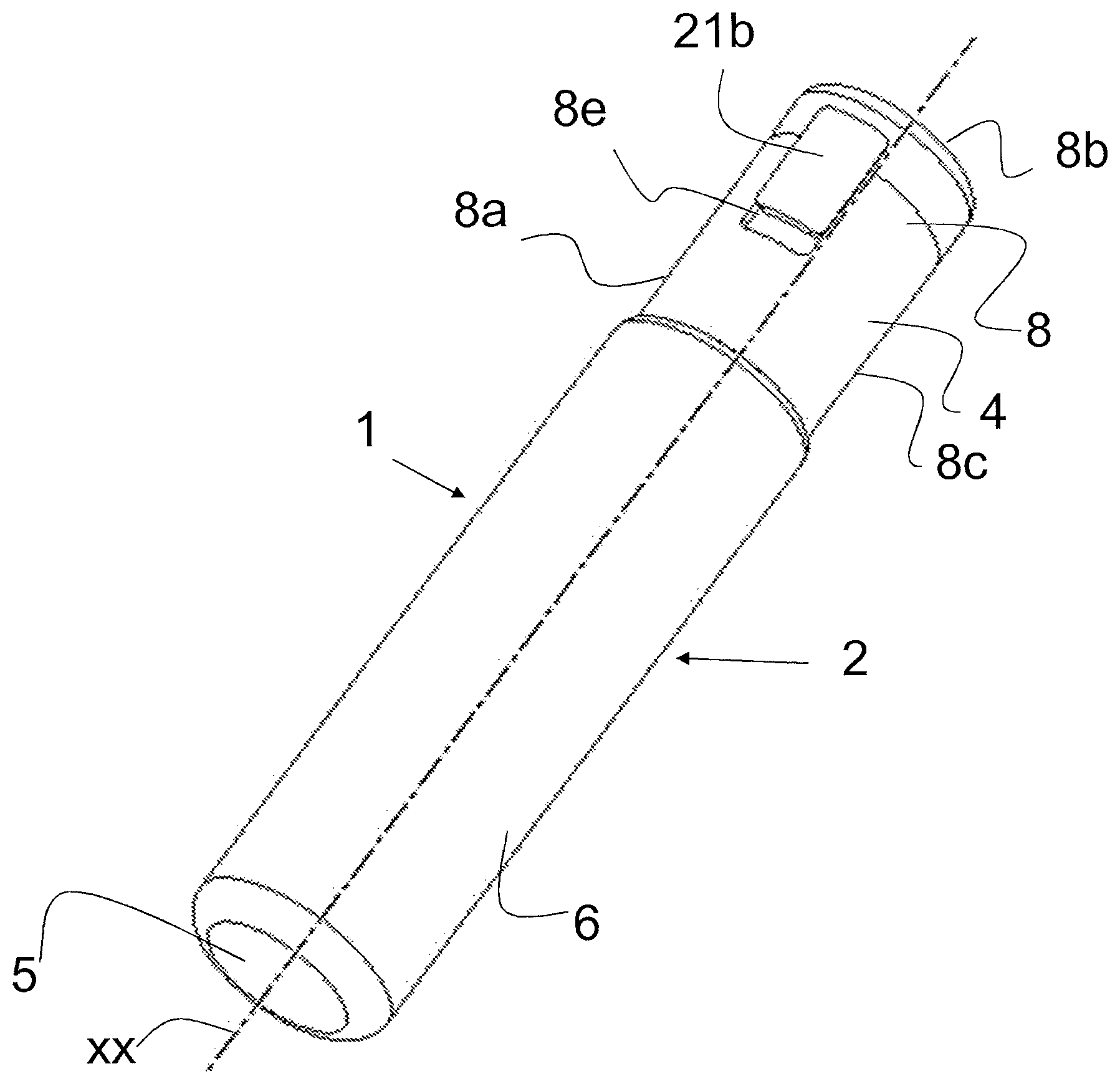
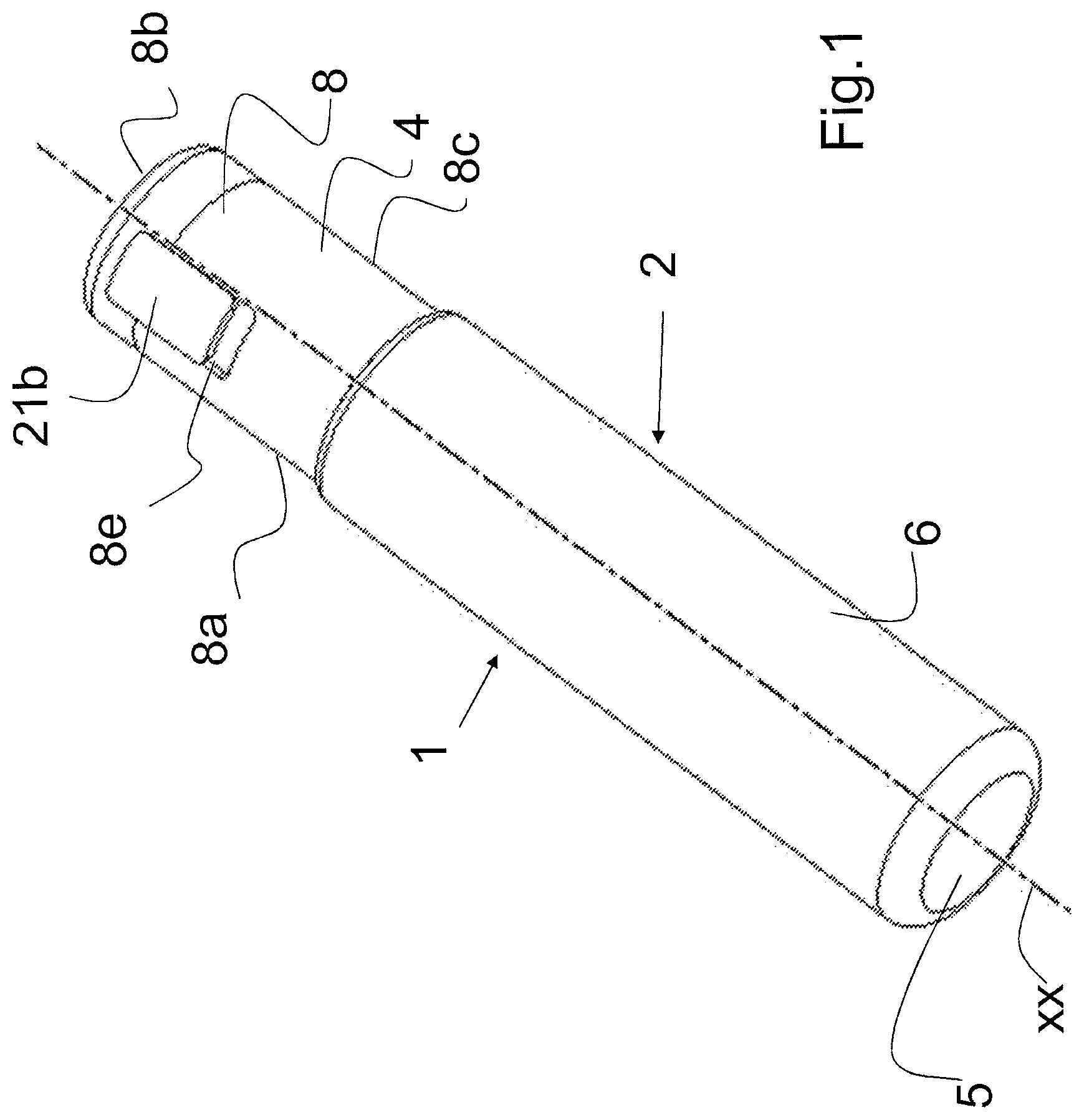
6. The application device according to claim 4, wherein: in the centered position, the two application sub-portions of the first distal section are adjacent to each other, while the two application sub-portions of the second proximal section are spaced from each other with interposition between them of the second terminal section of the rod portion, in an extreme inclined position, the two application sub-portions of the proximal second section are adjacent to each other, the articulation means are arranged such that when the application portion is pivoted between the centred position and the extreme inclined position, the two application sub-portions move relative to each other, away for the first distal section and closer for the second proximal section.
7. The application device according to claim 1, wherein the pivoting stroke of the application portion between the centered and extreme inclined positions is between 45.degree. and 135.degree..
8. The application device according to claim 1, wherein the articulation zone, the articulation means and the pivot axis are located away from the mid-point of the support member by being spaced from each of its both ends by different distances, with on one side a section of shorter length and on the other a section of longer length, the ratio between the length of the longer section and the length of the shorter section being of the order of 1.5 to 2.5, in particular equal to or of the order of 2, the shorter section being located on the side of the part with the greater radius of curvature of the outer shell of the application members and the longer section being, located on the side of the part with the smaller radius of curvature of the outer shell of the application members.
9. The application device according to claims 1, wherein the articulation means comprises a rack arranged on the second end portion of the rod portion, so as to extend in the direction of the rod portion and at least one toothed wheel cooperating with the rack, carried so as to be pivotable by the support member of the application portion, the toothed wheel and the rack being arranged so as to be in permanent engagement, the application deviceZ further comprising and integrating means for controlling the pivoting of the application portion comprising a rod disposed in a recess provided in the rod portion and arranged so as to be slidable in the direction of the rod portion and a control knob attached to a first end of the rod, disposed so as to be accessible from the outside through a hole provided in the side skirt of the handling cap.
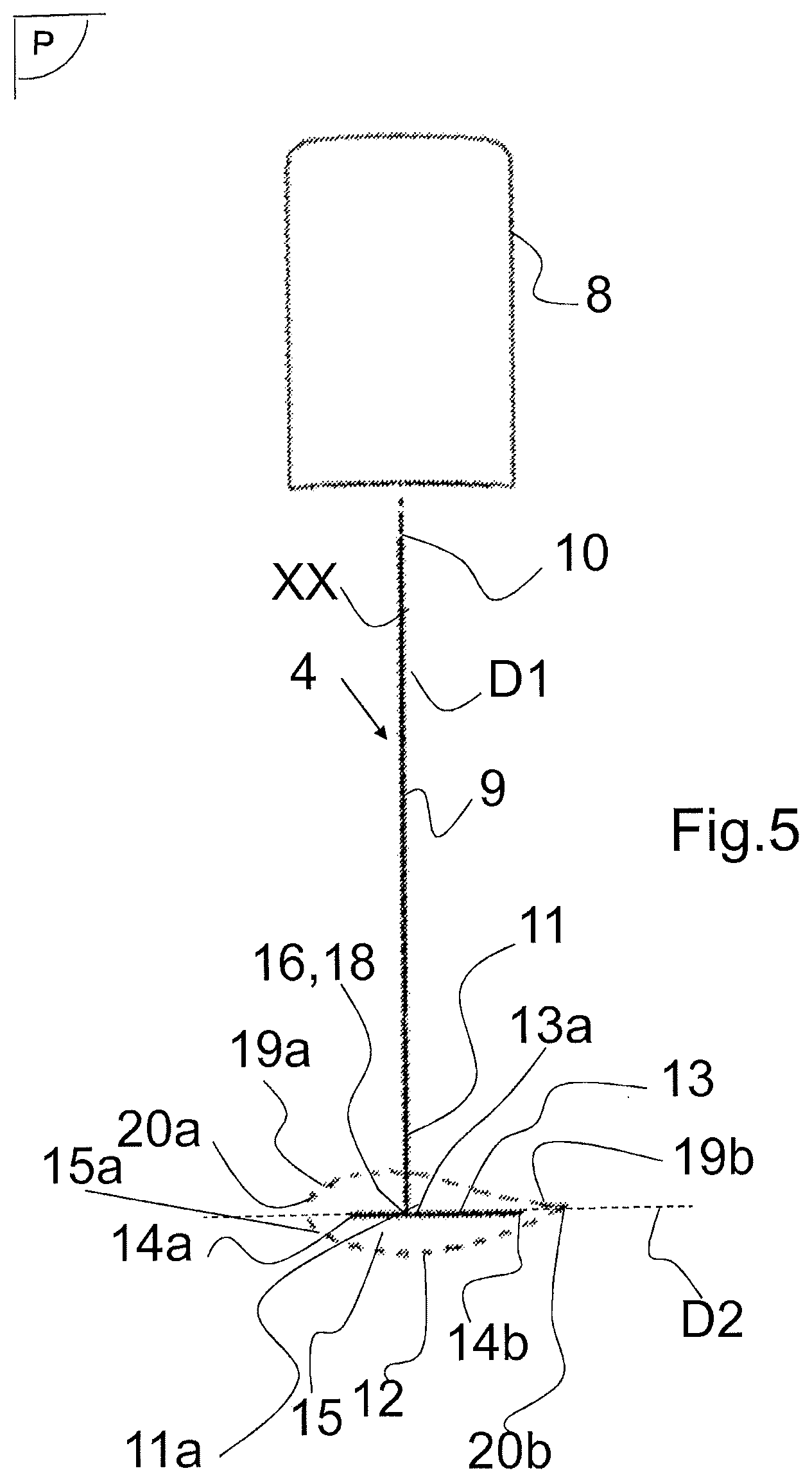
10. An assembly comprising a reservoir provided with an opening, suitable and intended to receive cosmetic products, such as mascara, or another product equivalent with regard to ergonomic conditions, and an the application device suitable to be associated with or dissociated from the reservoir, according to claim 1.
11. A method for operating the assembly according to claim 10, starting from a state in which the application device is dissociated from the reservoir, and handling the application device through the handling cap, which consists in: bringing the application device into the centred position if it is not already centred, introducing into the reservoir, through its opening, at least the application portion of the application device in the centred position, and loading it with mascara, extracting from the reservoir, through its opening, the application portion loaded with mascara, bringing the application device into an inclined position suitable for the application, applying the application members onto keratin fibres (eyelashes, eyebrows).
12. The A method according to claim 11, wherein the mascara-loaded application portion is extracted from the reservoir through its opening while it is in the centred position and the application device is brought into an inclined position suitable for the intended application once it has been completely extracted from the reservoir.
13. The method according to claim 12, wherein while the application portion is in the reservoir, the application device is brought into an inclined position to be loaded with mascara located on the inner side of the side wall of the reservoir, then brought into the centered position to be extracted from the reservoir.
Description
[0001] The invention relates to the application of a cosmetic product, such as mascara, more precisely a device for applying such a product (referred to by ellipsis as the "application device") onto keratin fibres (eyelashes, eyebrows), an assembly comprising such an application device and a reservoir for cosmetic product and the method of applying such an assembly and more especially the application device.
[0002] An assembly comprising a mascara reservoir and a mascara application device, provided with one opening in which a wiper is mounted and through which the application device passes during its introduction, extraction and loading with mascara. The design of the reservoir and the application device are mutually adapted. In a known standard, the reservoir is a tube and the assembly is called by ellipsis, a "mascara tube".
[0003] JP S60 70216 U describes such an application device comprising: [0004] a handling cap suitable and intended to close the reservoir and a means for holding, moving and manoeuvring the application device, [0005] an elongated rod portion, having a main direction, a first end where it is associated with the handling cap and a second end portion including a second end portion that terminates it, [0006] an elongated mascara application portion extending along a main axis, comprising a support member having two ends, provided at its periphery with radial application members--such as hairs, tips, fibres, spongy elements--hingedly mounted in an articulation zone and by articulation means on the rod portion at its second end portion, about a pivot axis orthogonal to a main radial pivot plane defined by the axis of the application portion and the direction of the rod portion, so that it can occupy a centred position and an extreme inclined position in which said axis and said direction are inclined with respect to each other at most, and to be pivoted from one to the other of these two positions, by means of a pivot stroke, [0007] the articulation zone, the articulation means and the pivot axis being located in the median section of the support member, spaced from both ends.
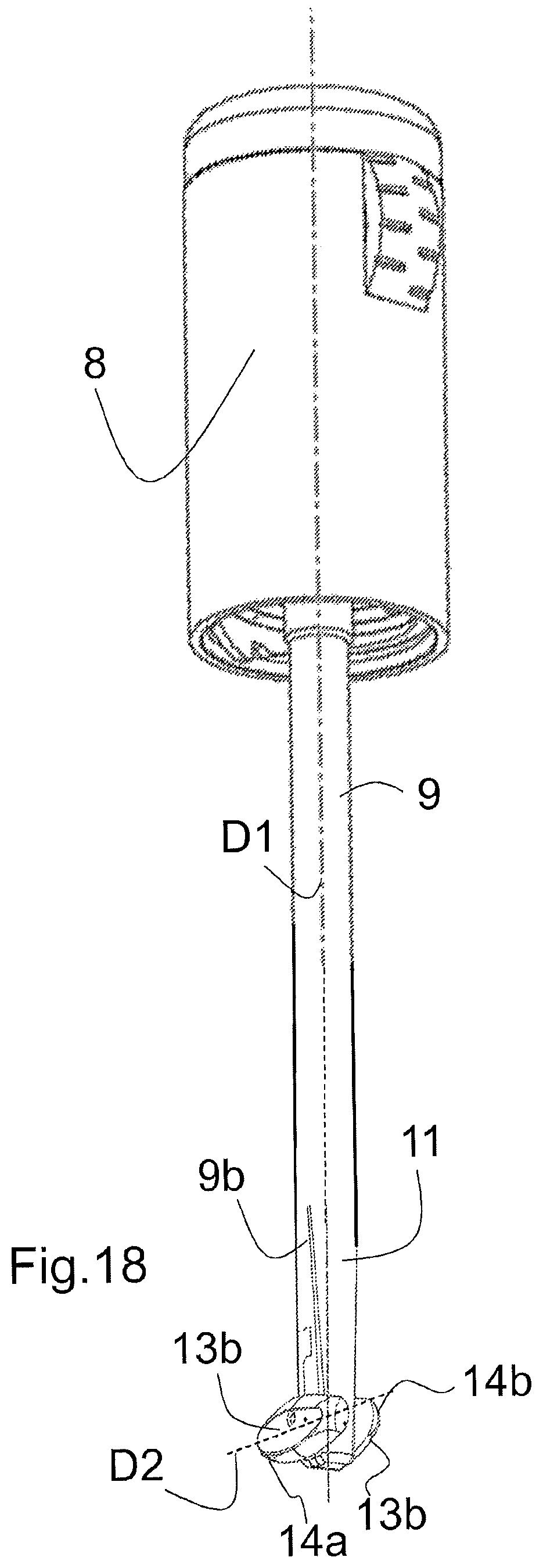
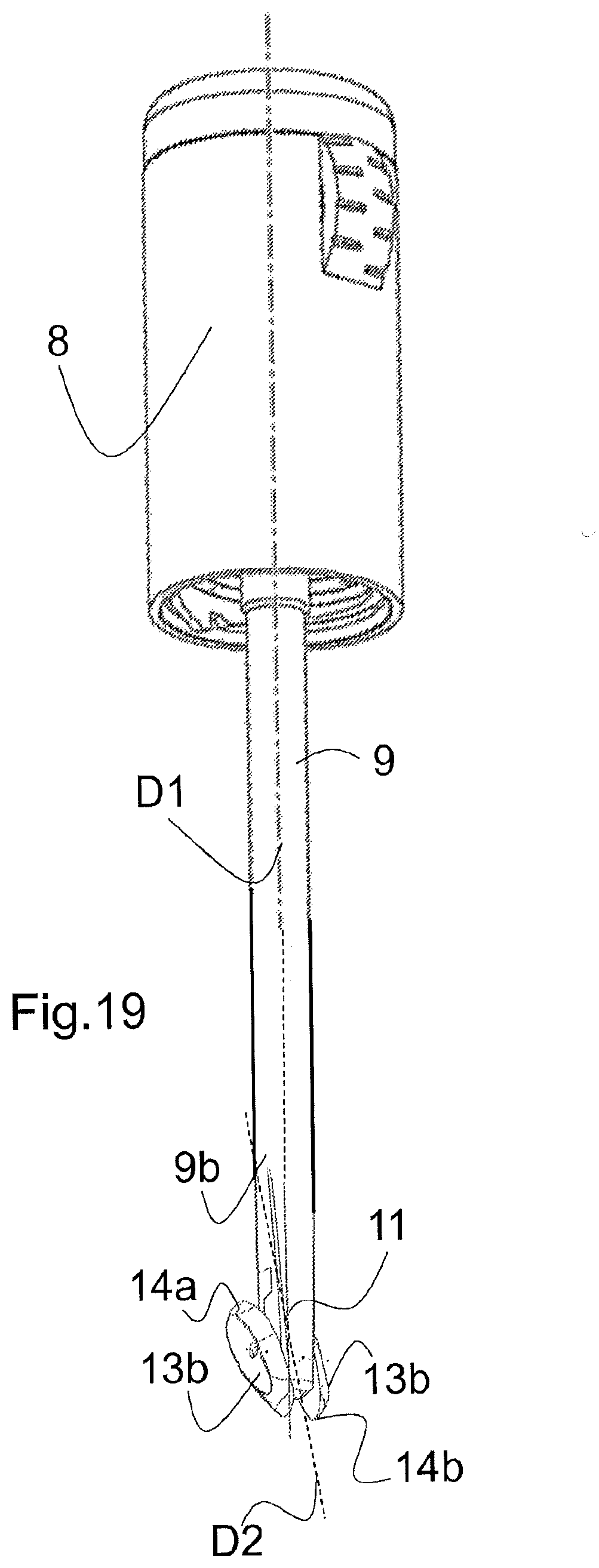
[0008] According to JP S60 70216 U, the application portion is in one part, the support member is a single-piece, the application members can only be located on a part of the radial periphery of the support member, both ends of which are exposed and protrude from the outer shell of the application members, which is a source of injury, the support member not being entirely included in the outer shell of the application members.
[0009] JP S60 70216 U describes a device with aggravated disadvantages and a rack-and-pinion travel control system. The articulation area, the articulation means and the pivot axis are located at a first articulation end of the support member which is completely outside the outer shell of the application members and even spaced therefrom, so that the articulation end of the application portion is unusable for mascara application and even annoying, being exposed and prominent, it is hurtful to the user and may become clogged.
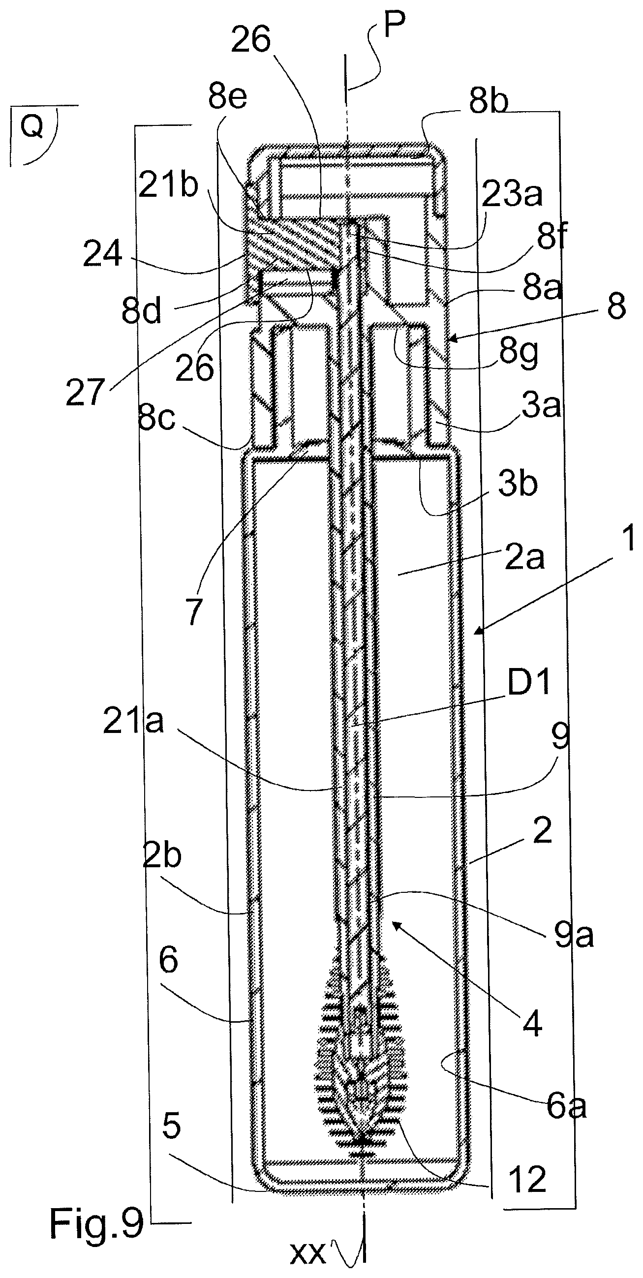
[0010] The application of mascara involves constraints and requirements that are ergonomic conditions. The application must be made with gentleness, delicacy, precision, in a similar way for both eyes, and it must not be hurtful. When the user applies mascara himself/herself, it is often difficult for him/her to adopt the ideal hand gestures, as his/her vision is affected by the presence of his/her own hand and it is difficult to adapt the gestures to the side where the eye is located. In addition to the ergonomic conditions of application, there are ergonomic conditions for introduction, extraction and loading. This means that the introduction of the application portion through the opening of the reservoir can be done intuitively, easily, quickly and correctly and that the application members are correctly loaded with mascara.
[0011] The invention relates to other products than cosmetics, if the ergonomic conditions are identical or similar to those of mascara, the terms "cosmetic product" and "mascara" being understood as including equivalent products with regard to ergonomic conditions.
[0012] In a standard embodiment, the application portion is rigidly attached to the rod portion by extending it. In U.S. Pat. No. 5,188,131, the application portion is rigidly mounted in a rigid association zone on the rod portion transversely. In U.S. Pat. No. 6,505,632, the application portion is fixedly mounted in its center on the rod portion. In JP 2005/237395, the application portion is fixedly mounted at one end on the rod portion. In EP 2 789 259, U.S. Pat. No. 4,165,755, WO 2015/124550 and US 2014/0016984, the application portion is in a single straight section and in U.S. Pat. No. 8,783,989 it is in two rigid straight sections.
[0013] Thus, there is a need to have, for mascara or products equivalent in terms of ergonomic conditions, an application device and an assembly also comprising a reservoir, which have the ergonomic characteristics likely to satisfy the ergonomic conditions of application and the ergonomic introduction, extraction and loading conditions previously exposed. This need must be met under acceptable manufacturing conditions and at acceptable prices. This is the problem whereon the invention is based.
[0014] A disclosure of the invention as characterized shall be exposed below.
[0015] According to a first aspect, the invention relates to a device for applying a cosmetic product, such as mascara, or another product equivalent in terms of ergonomics, suitable and intended to be associated with a mascara reservoir, of the type described above, in which: [0016] the application portion consists of two adjacent similar application sub-portions arranged opposite each other relative to the pivot plane, [0017] the support member is formed by two similar support sub-members, arranged opposite and close to each other relative to the pivot plane with interposition between them of the second end portion of the rod portion and the articulation means.
[0018] According to one embodiment, the application portion comprises a first section between the pivot axis and a first end and a second section between the pivot axis and a second end, the first section and the second section being mutually extended, the second end portion of the rod portion being located between the two sections.
[0019] According to one embodiment, in a centered position, the first distal section is arranged in the axial extension of the rod portion, beyond its second end portion, while the second proximal section is located at the level of the second end section of the rod portion. And, in an extreme inclined position, the first and second sections extend transversely on either side of the rod portion respectively.
[0020] According to one embodiment, both ends of the support member are included in the outer shell of the application members and undiscovered and prominent, the application members extending axially beyond each of these two ends, and the support member is entirely included in this outer shell, more particularly is entirely spaced inwardly from the outer shell of the application members.
[0021] Possibly, this outer shell has an ellipsoidal shape elongated in the axis of the application portion, as an ovoid assembly shape with on one side a part with a larger radius of curvature and on the opposite side a part with a smaller radius of curvature. Possibly, the part with the larger radius of curvature belongs to the first, distal section of the application portion and the part with the smaller radius of curvature belongs to the second, proximal section of the application portion.
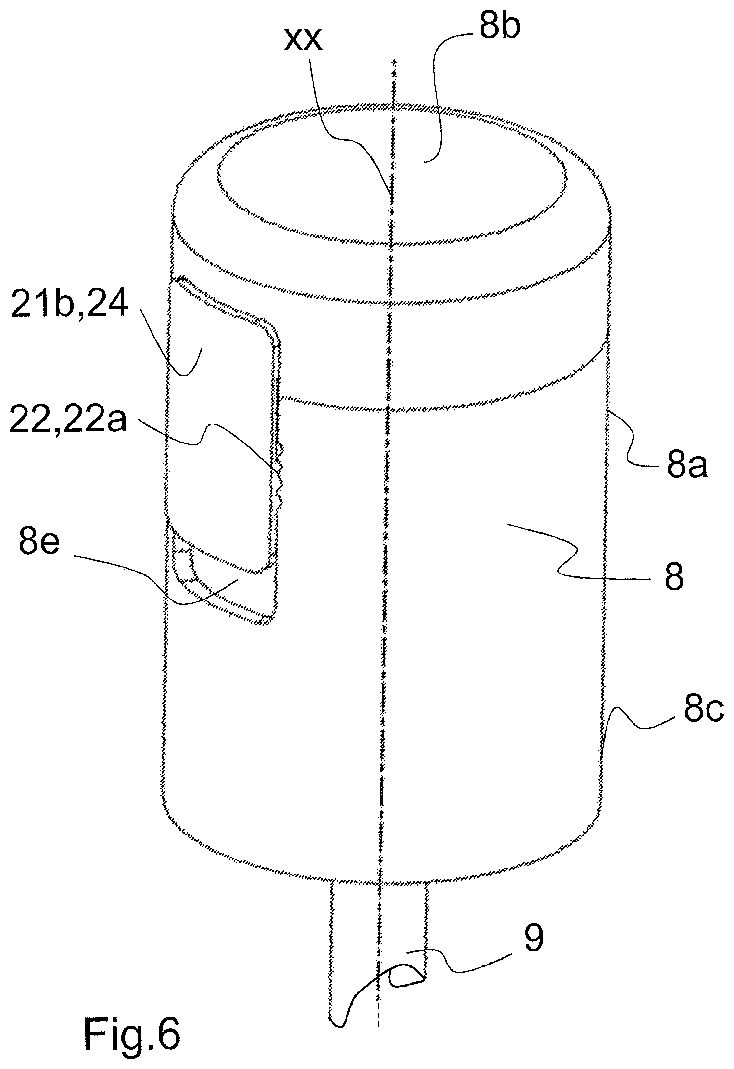
[0022] According to one embodiment, the application portion is formed by two application sub-portions which are arranged symmetrically with respect to the pivot plane and which occupy the same relative angular position and rotate in synchronism, and the support member is formed by two support sub-portions which are arranged symmetrically with respect to the pivot plane and which occupy the same relative angular position and rotate in synchronism.
[0023] According to one embodiment, the application device includes two subsets of application devices, for the two support members, the arrangement of which provides outward continuity between the two subsets of application devices.
[0024] Possibly, each of the two application sub-portions and each of the two support sub-members has a shape of a half ellipsoidal assembly cut in the direction of the major axis, more particularly a semi-oval assembly shape with on one side a part with a larger radius of curvature and on the opposite side a part with a smaller radius of curvature. In the centred position, the respective portions of the two sub-assemblies of the application members towards the part with a larger radius of curvature are intertwined.
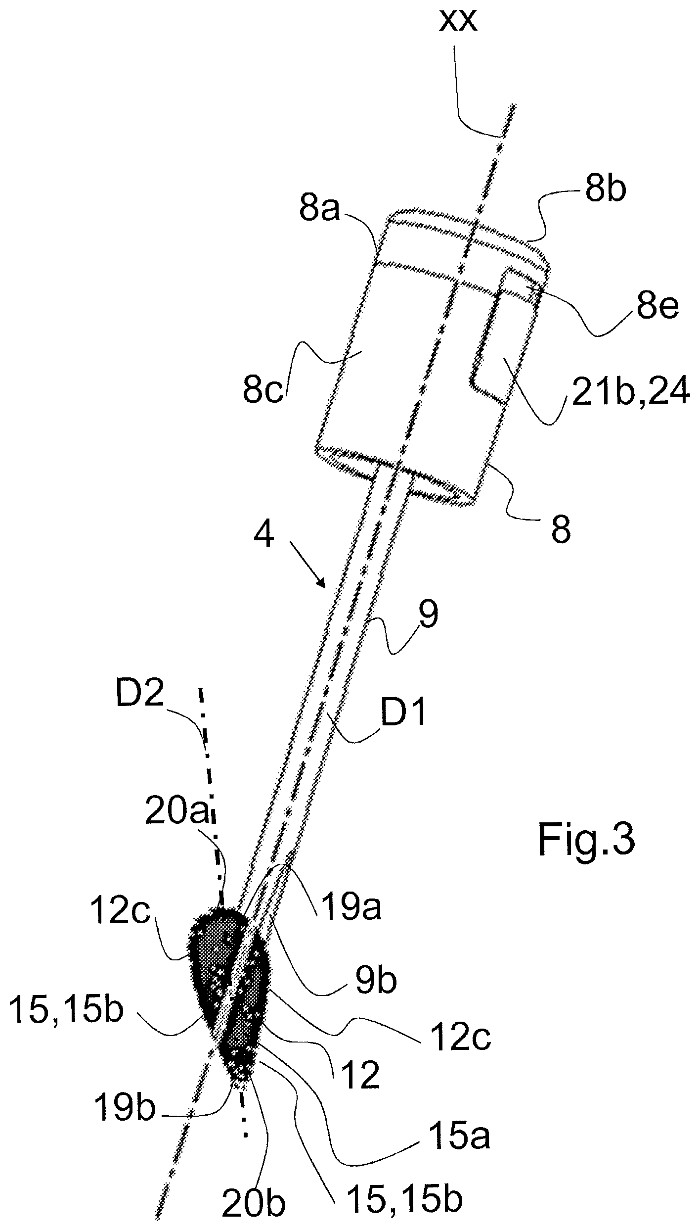
[0025] Each of the two application sub-portions is limited on the side of the second end portion of the rod portion by a generally flat shell face extending in the general direction of the pivot plane and in the vicinity of this plane. And each of the two support sub-members is limited on this second end portion side by a generally flat shell face that extends in the general direction of the pivot plane, near this plane, and which is adjacent to this second end portion. Possibly, the two faces limiting the two application sub-portions and the two support sub-portions towards this second end portion are spaced from each other in the direction of the pivot axis of the application portion.
[0026] In the centred position, the two application sub-portions of the first distal section are adjacent to each other, and the two application sub-portions of the proximal second section are spaced from each other with the interposition of said second terminal section. In an extreme inclined position, the two application sub-portions are adjacent.
[0027] The articulation means are arranged so that when the application portion is pivoted, the two application sub-portions move away for the first distal section and closer for the second proximal section.
[0028] Possibly, each of the two support sub-members is rigid and the support element, respectively each of the two support sub-members, has a straight axis.
[0029] Possibly, the articulation zone, the articulation means and the pivot axis are located in a central position on the support member, being spaced from each other at both ends either by the same or different distances, with a section of shorter length on one side and a section of longer length on the other.
[0030] According to one embodiment, the articulation means comprise a rack arranged on the second end portion of the rod portion and extending in the direction of the rod portion and a toothed wheel cooperating with the rack, pivoted by the support member, the toothed wheel and the rack being in permanent engagement. The application device may include and incorporate means to control the pivoting of the application portion, such as locking, braking or friction means.
[0031] According to one embodiment, the means for controlling the pivoting of the application portion comprise a rod arranged in a recess in the rod portion and arranged so as to be slidable in the direction of the rod portion, in both directions, ridgedly associated by its second end with the end of the rack, and a control knob attached to a first end of the rod, arranged so as to be accessible from the outside through a hole of the side skirt of the handling cap, elongated so that the control knob can slide in the hole.
[0032] According to a second aspect, the invention relates to an assembly comprising a reservoir provided with an opening, suitable and intended to receive cosmetic products, such as mascara, or another product equivalent with regard to ergonomic conditions, and an application device suitable to be associated with or dissociated from the reservoir, as just described.
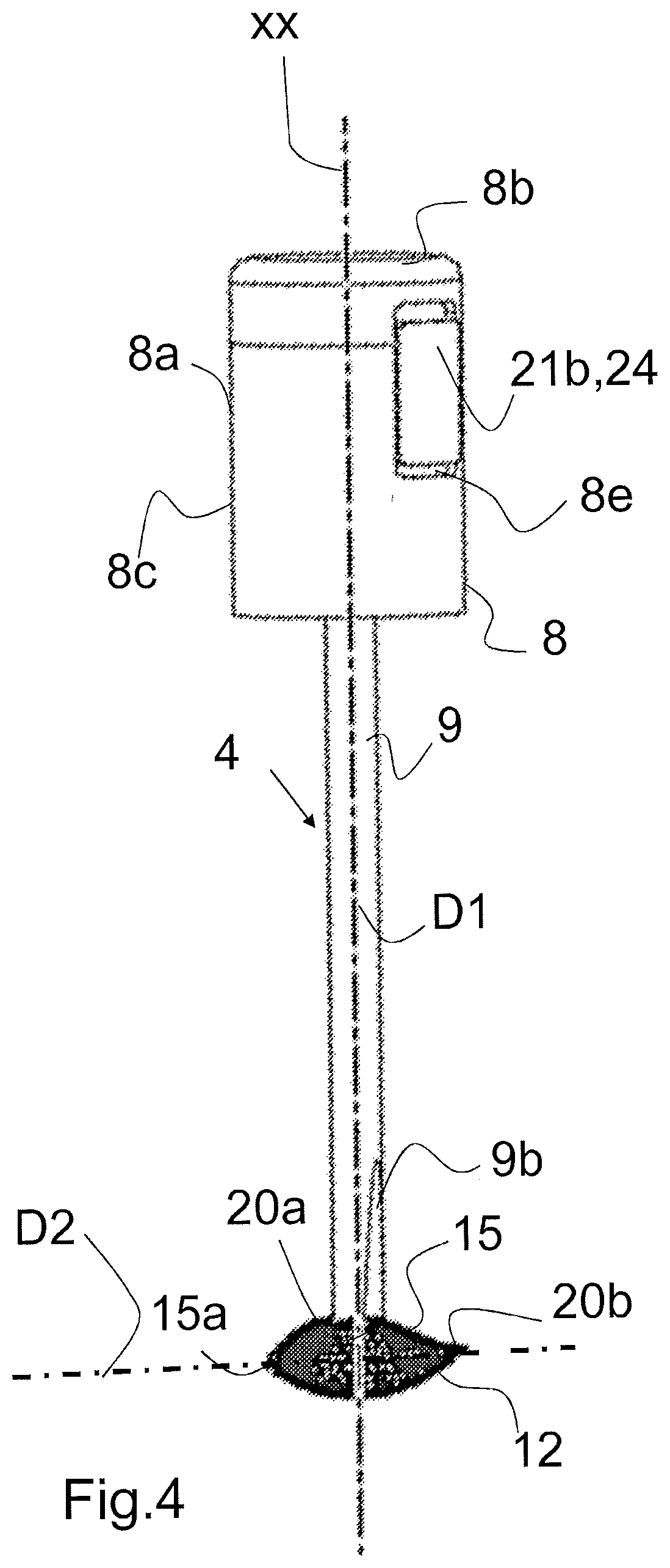
[0033] According to a third aspect, the purpose of the invention is a method for implementing such an assembly, starting from a state in which the application device is dissociated from the reservoir, and handling the application device with the handling cap, which consists in: [0034] bringing the application device into the centred position if it is not already centred, [0035] introducing into the reservoir, through the opening thereof, at least the application portion of the application device in the centred position, and loading it with mascara, [0036] extracting from the reservoir, through its opening, the part of the application loaded with mascara, [0037] bringing the application device into an inclined position suitable for the application, [0038] applying the application members onto keratin fibres (eyelashes, eyebrows).
[0039] The figures are now briefly described.
[0040] FIG. 1 is a perspective view of an assembly comprising a reservoir and an application device associated with the reservoir with a handling cap visible that has a hole in its side skirt.
[0041] FIG. 2 is a perspective view of the application device of the entire FIG. 1, in which the support member is centered.
[0042] FIG. 3 is a perspective view of the application device of FIG. 2, shown in an intermediate inclined position.
[0043] FIG. 4 is a perspective view of the application device in FIGS. 2 and 3, which is in an extreme inclined position at about 90.degree..
[0044] FIG. 5 is a simplified diagram corresponding to FIG. 4, symbolically illustrating, on the one hand, the support member at both ends of the application portion intended to be provided, at its periphery with radial application members and, on the other hand, the application portion.
[0045] FIG. 6 is a partial view of FIG. 1 on a larger scale, showing the handling cap with its hole, the control knob and additional blocking reliefs allowing reciprocal blocking in several positions.
[0046] FIG. 7 is a perspective view of the application device in the hand of a user, whose thumb can slide the control knob.
[0047] FIGS. 8 and 9 are two axial cross-sectional views of the assembly shown in FIG. 1, respectively in a main radial pivot plane and in a plane orthogonal to the previous one called the travel reference plane; these figures illustrate that the outer shell of the application members has an ovoid ellipsoidal assembly shape with on one side a part with a larger radius of curvature and on the opposite side a part with a smaller radius of curvature, the part with a larger radius of curvature belonging to the first, distal section of the application portion and the part with a smaller radius of curvature belonging to its second, proximal section.
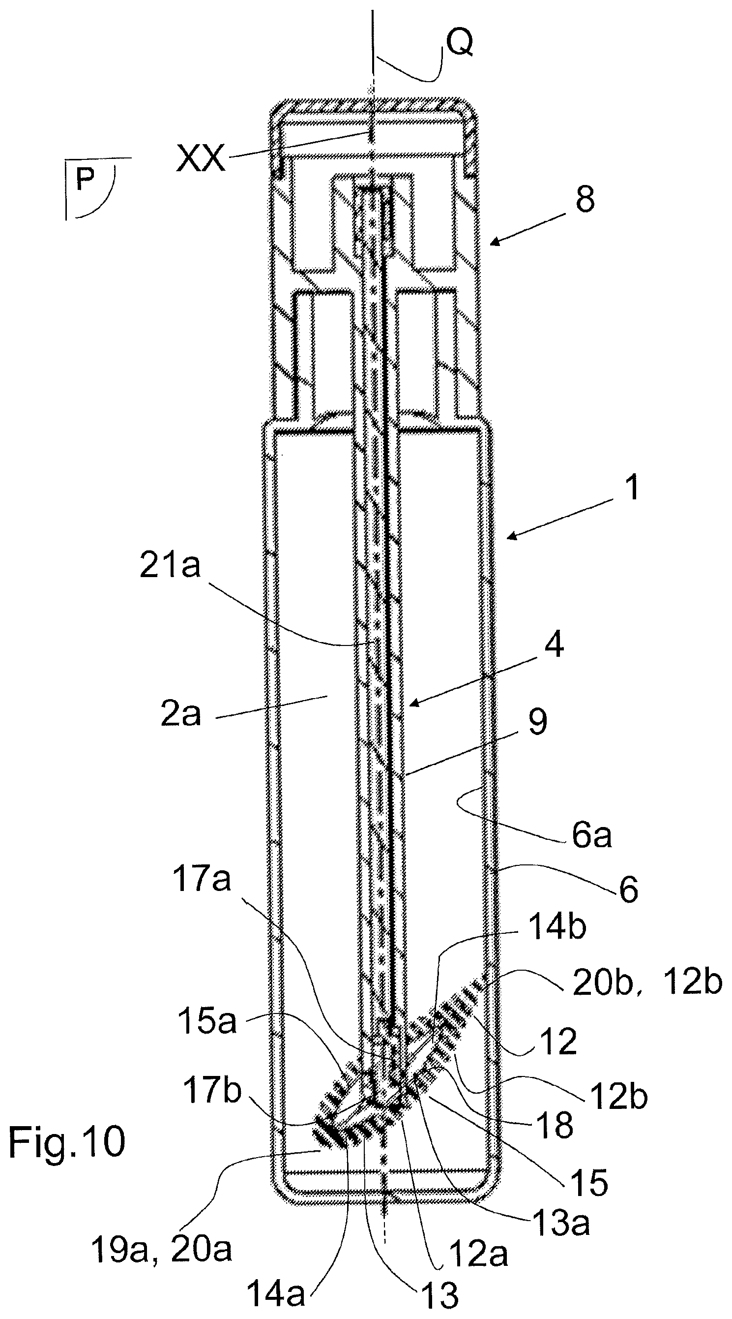
[0048] FIG. 10 is an axial cross-sectional view similar to FIG. 8, in which the axis of the application portion and the direction of the rod portion are inclined relative to each other.
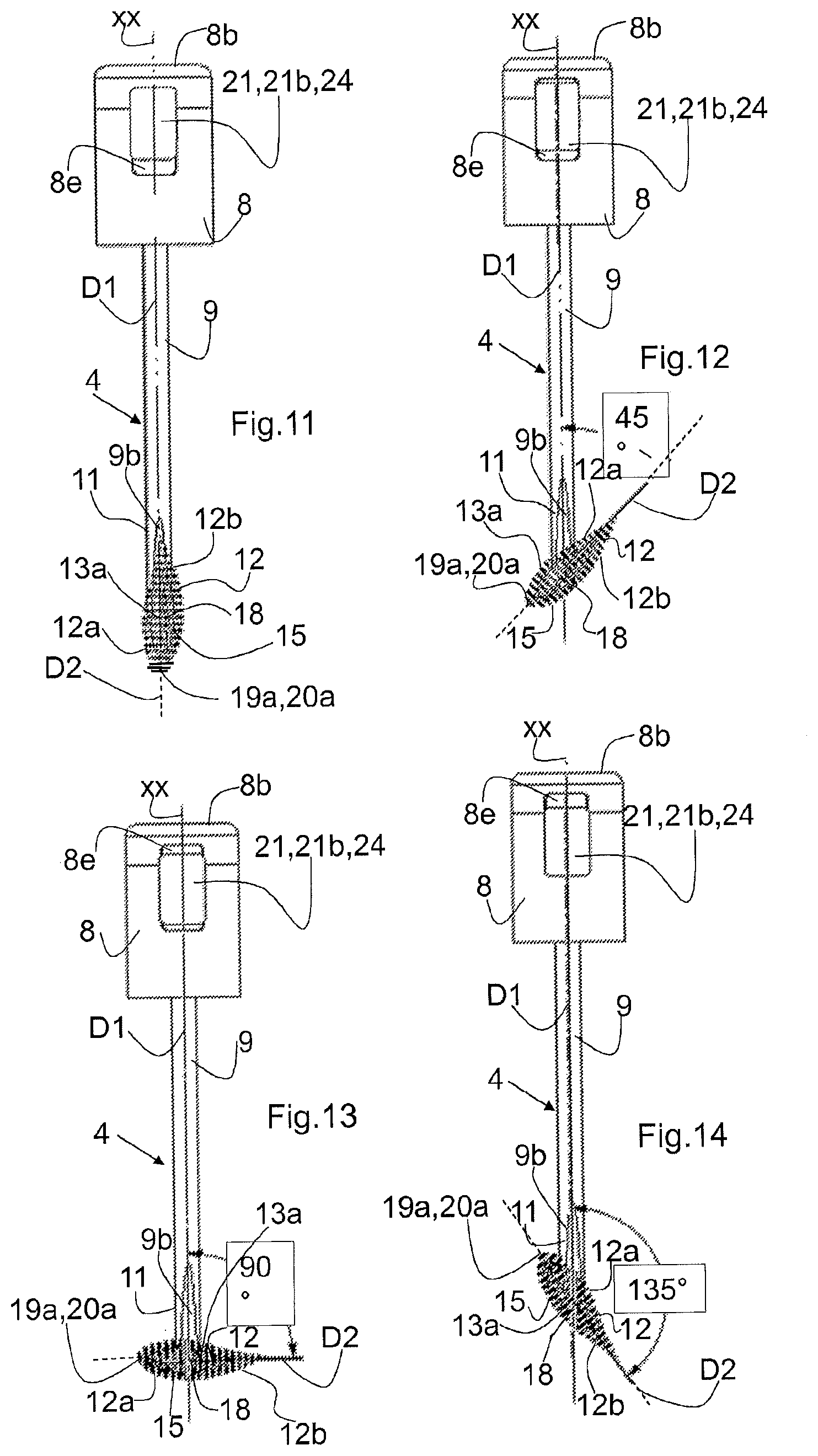
[0049] FIG. 11 is an elevation view of the application device in a plane parallel to the pivot plane, located in the centred position shown in FIG. 2.
[0050] FIGS. 12, 13 and 14 are three elevation views of the application device in intermediate (FIGS. 12 and 13) and extreme (FIG. 14) inclined positions; these figures illustrate that the two ends of the support member are included in the outer shell of the application members and undiscovered and prominent, the application members extending axially beyond each of these two ends, the support member, including its two ends, being entirely included in the outer shell of the application members, and even entirely spaced towards the inside of this shell.
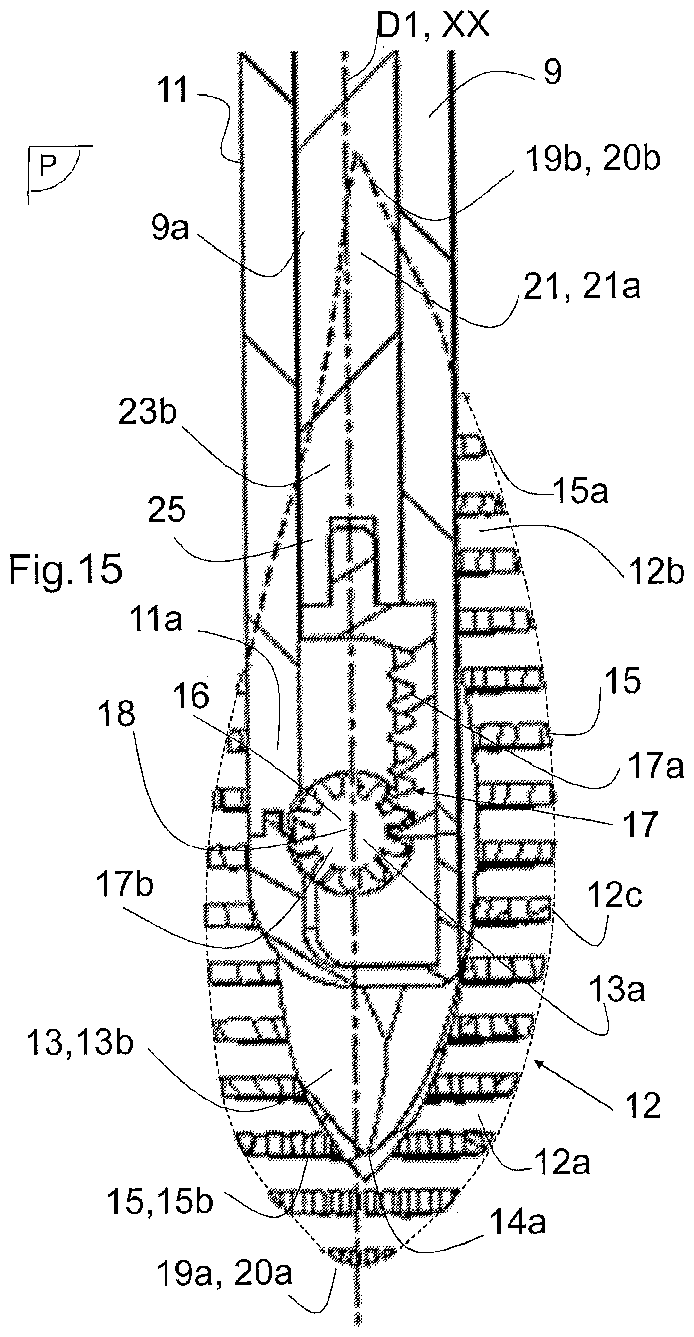
[0051] FIG. 15 is a partial view on a larger scale, in cross-section along the pivot plane.
[0052] FIGS. 16, 17, 18 and 19 are four partial views in perspective of the application device, illustrating the configuration of the support member in different positions.
[0053] A disclosure of the several embodiments shall be exposed below while referring to the figures.
[0054] The invention relates to an assembly 1 comprising a reservoir 2, provided with one opening 3, forming an internal cavity 2a, suitable and intended to receive cosmetic products, such as mascara, or another product equivalent with regard to ergonomic conditions, and an application device 4, suitable to be associated with the reservoir 2 when the assembly 1 is not used or separated from it to use the application device 4 by applying it onto keratin fibres, such as eyelashes and eyebrows to deposit mascara thereon. The cosmetic product is sometimes later referred to as "contents", by ellipsis.
[0055] An "application device" means a structural and functional entity that can be handled by a user with the hand by a handling portion and that is provided with an application portion having application members--such as hairs, tips, fibres, spongy elements--so that these application members can be filled with mascara from a reservoir and applied, generally by being moved, onto keratin fibres to deposit mascara, and if necessary produce an effect.
[0056] The reservoir 2 behaves as an assembly, being rigid (which includes substantially rigid). It may have a general cylindrical shape with a circular or pseudo-circular guide curve and a rectilinear or pseudo-rectilinear generator, for example in the general shape of a tube, with the opening 3 formed at the end of a narrowed diameter neck 3a, associated with the main portion 2b of the reservoir 2 by a shoulder 3b.
[0057] The internal cavity 2a of the reservoir 2 can be limited, on one end by a more or less flat bottom 5, on the other end by the shoulder 3b and the neck 3a, and laterally by a peripheral side wall 6 having an inner face 6a in contact with the contents.
[0058] The reservoir 2 has a single opening 3 with a circular or pseudo-circular contour, which is used for the passage of the application device 4, in both directions, inwards (introduction) and outwards (extraction) of the reservoir 2, by simply sliding along the axis XX. It can have a wiper 7 associated with the opening 3, for example at the neck 3a.
[0059] In the case of mascara, the reservoir 2 can have a capacity of about 1 ml to 15 ml, an axial height of less than 1 cm to 15 cm and an external diameter of about 5 ml to 20 ml. Such a reservoir 2 can be transparent, translucent, opaque. It can be made of plastic material, glass or metal
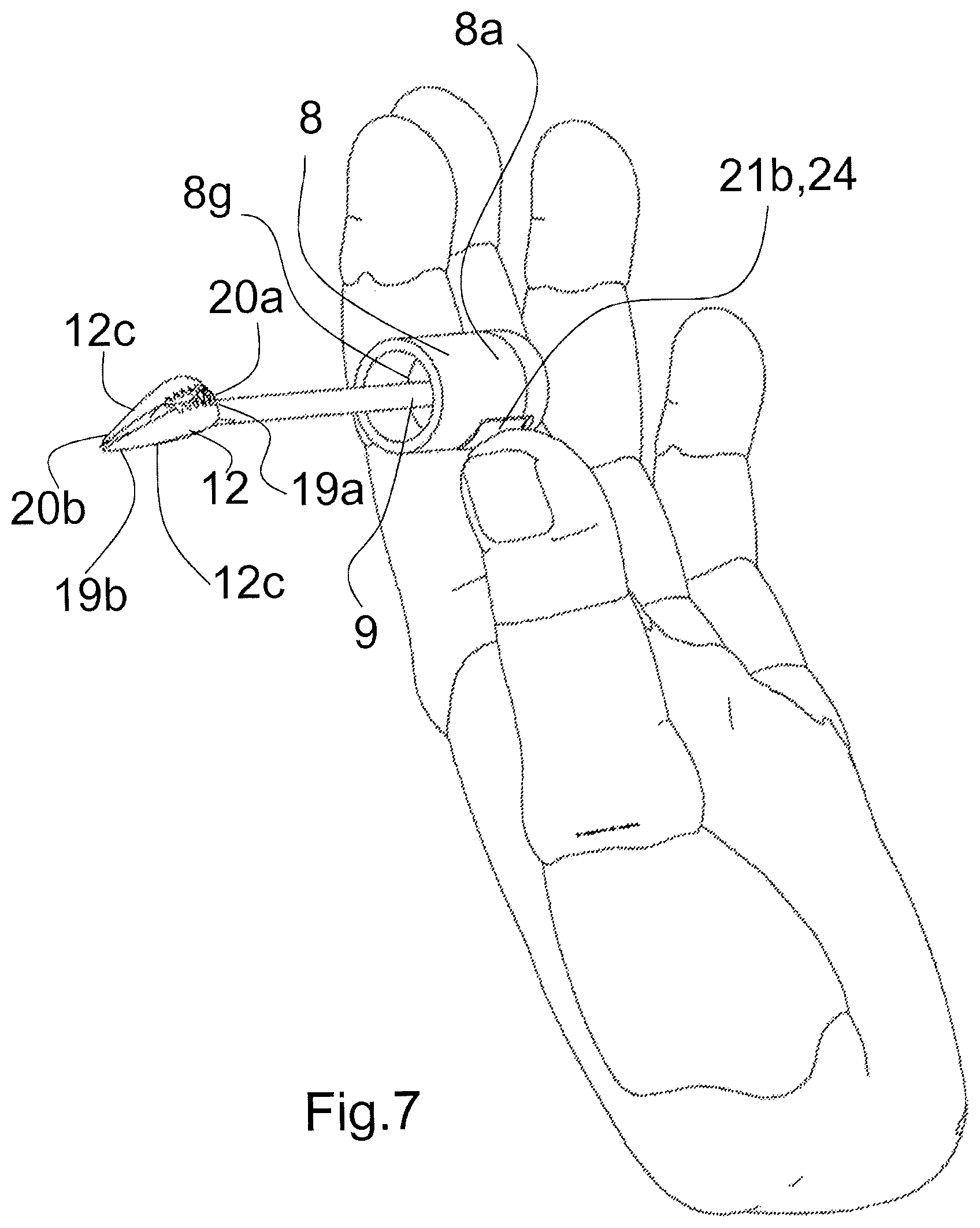
[0060] While the application device 4 has a different shape and structure from those known, the invention allows a known per se and classic reservoir for a mascara and its introduction into, or extraction from, the reservoir by simply sliding along the axis XX, according to a known per se and classic gesture.
[0061] When not in use, the set 1 can be placed with its axis XX vertical, resting on its bottom 5, with the opening 3 and the neck 3a being placed higher (FIGS. 8 to 10).
[0062] The reservoir 2 may be embodied in other ways than those described.
[0063] The invention relates to the set 1 the cavity 2a of which is filled with the contents, and the set 1 the cavity 2a of which has no contents. The invention also relates to the mounted assembly 1, the application device 4 being physically associated with the reservoir 2, and the dismounted assembly 1, with the application device 4 being physically separated from the reservoir 2. The invention also relates to the application device 4 itself, and as far as it is intended to be physically and functionally associated with the reservoir 2.
[0064] The application device 4 includes a terminal handling cap 8, that terminates the application device 4 on one side. The cap 8 is used to close the reservoir 2. It is also a means for holding, moving and manoeuvring the application device 4 with the user's hand. These are its functions, with the cap 8 possibly being embodied in many ways. For example, the cap 8 may have a shape similar to that of the reservoir 2 with a cylindrical shape having a circular or pseudo-circular guide curve and a rectilinear or pseudo-rectilinear generator.
[0065] The cap 8 has a peripheral skirt 8a and a transverse vertex 8b on the side. Towards the opposite of the transverse vertex 8b, the peripheral skirt 8a is extended by an extension of skirt 8c provided towards its inner face with means for the removable association of the cap 8 to the neck 3a (screw threads, pins), complementary to means of association provided on the neck 3a. This skirt extension 8c laterally surrounds the neck 3a. Like the reservoir 2, the handling cap 8 has an axis that is referenced XX.
[0066] The handling cap 8 can have a cavity 8d inside which axially extends along the axis XX and also radially to and from the axis XX. This cavity 8d leads to the peripheral skirt 8a through a hole 8e which is elongated in the axial direction XX. This cavity 8d has on the axis XX side a terminal cavity 8f (FIG. 9).
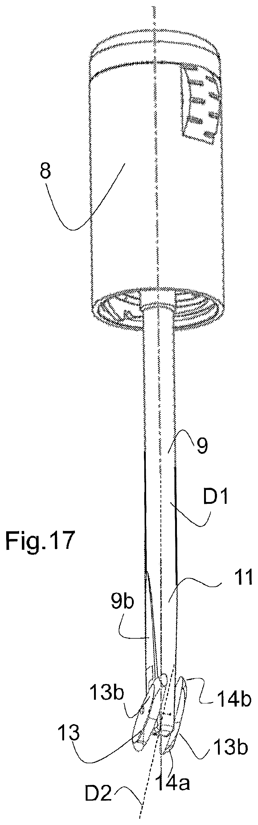
[0067] The application device 4 consists of a second part 9, called the rod portion 9, which is elongated and thin, justifying the term "rod". It has an overall rigidity and a main direction D1, rectilinear in the represented embodiment.
[0068] The rod portion 9 has a first end 10 where it is rigidly associated with the handling cap 8, for example in its median inner part, so as to form a one-piece assembly. For example, the handling cap 8 has a transverse wall 8g inside, between the peripheral skirt 8a and the skirt extension 8c which has the function of closing the opening 4 and rigidly carrying the rod portion 9 by its first end 10, for example by welding. Or the handling cap 8 and the rod portion 9 form a single-piece unit. The rod portion 9 has a second terminal section 11 including a second end portion 11a which terminates it.
[0069] The rod portion 9 has an axial channel 9a, opening at both ends, namely the first end 10 and the second end portion 11a. On the first end 10 side, the channel 9a opens into the terminal recess 8f of the handling cap 8.
[0070] Thirdly, the application device 4 consists of a portion 12, called mascara application portion 12, or by ellipsis, an application portion 12. The application portion 12 is elongated and extends along astraight or possibly slightly curved main axis D2. The application portion 12 includes a support member 13, also elongated along the main axis D2, and having two ends 14a and 14b. This support member 13 is rigid (which must be understood as having a certain overall rigidity) and is equipped and furnished with radial application members 15 on its periphery. These application members 15 are qualified as radial insofar as they extend in a general globally radial direction perpendicular to the main axis D2. These application members 15 are arranged on the lateral periphery of the support member 13, around the main axis D2. The functions of these application members 15 are to be loaded with some contents from the reservoir 2 and to be applied, generally by being moved, onto the support where the contents is to be applied. These application members 15 can be the subject of a number of embodiments. They can be in the form of hairs, tips, fibres, spongy elements.
[0071] The application portion 12 is associated with the rod portion 9 at its second end portion 11 a, so as to than a single-piece unit therewith. Due to the length of the rod portion 9 in the main direction D1, the application portion 12 is moved away from the handling cap 8.
[0072] The dimensions of the application device 4 are related to the dimensions of the reservoir 2. The rod portion 9 and the application portion 12 must be able to pass through the opening 3 in cooperation with the wiper 7. When the application device 4 is mounted assembled on the reservoir 2, the application portion 12 is located near the bottom 5 and the handling cap 8 around the neck 3a.
[0073] The application portion 4 is mounted hinged in an articulation zone 16 and by articulation means 17 on the rod portion 9 at its second end portion 11a, about a pivot axis 18, orthogonal to a main radial pivot plane P defined by the axis D2 and the direction D1 (plane in FIG. 5). Q is a radial reference plane of travel, orthogonal to the pivot plane P (plane of FIG. 9). Instead of a perfect pivot axis, it can be a pivot zone around an axis.
[0074] With this hinge mounting, the application portion 4 can occupy a centered position in which the axis D2 and the direction D1 are coaxial (which also includes substantially coaxial), an extreme inclined position in which said axis D2 and said direction D1 are inclined with respect to each other at most, and any intermediate inclined position. With this assembly, the application portion 4 can be pivoted from one position to the other, centred and extreme inclined, or intermediate inclined position, and vice versa, by means of a pivoting stroke around the axis 18. FIGS. 2 to 5, 8 to 14 and 16 to 19 illustrate the various, i.e. centred, extreme inclined and intermediate inclined positions.
[0075] According to the embodiments, the pivot stroke of the application portion 12 between the centred and the extreme inclined positions is between 45.degree. and 135.degree., more particularly around 90.degree. (FIG. 4, 13) or 135.degree. (FIGS. 7, 14).
[0076] The articulation zone 16, the articulation means 17 and the pivot axis 18 are located in a median section 13a of the support member 13, being spaced from each one of its both ends 14a and 14b, so as not to be present there. The term "means" applied to the section 13a must be understood as referring to a support zone 13 that is spaced, in particular substantially apart, from both ends 14a and 14b of the support 13 (FIG. 5). On the other hand, the term "means" should not be understood as referring to a zone necessarily located at an equal distance from either end 14a and 14b.
[0077] In a possible embodiment (see drawings), the articulation zone 16, the articulation means 17 and the pivot axis 18 are located away from the mid-point of the support member 13 by being spaced apart from the two ends 14a and 14b by different distances, with on one side a section of shorter length and on the other side a section of longer length, the length ratio being of the order of 1.5 to 2.5 and in particular equal to or of the order of 2. In another possible embodiment, the articulation zone 16, the articulation means 17 and the pivot axis 18 are located in a central position on the support member 13, being spaced from both ends 14a and 14b by a similar distance.
[0078] The application portion 12 has two real sections 12a and 12b: a first section 12a between the pivot axis 18 and a first end 19a of the application portion 12 and a second section 12b between the pivot axis 18 and a second end 19b of the application portion 12. The first section 12a and the second section 12b are mutually extended, i.e. coaxial (which also includes substantially coaxial). The second end portion 11a of the rod portion 9 is located between the two sections 12a and 12b, as is especially visible in FIGS. 4, 7 and 16 to 19.
[0079] With the application device 4 in the centered position (FIGS. 2, 8, 11, 15, 16), one of the two sections 12a, 12b can be qualified as distal and the other as proximal. The terms "distal" and "proximal" refer to the distance between the handling cap 8 or the first end 10 of the rod portion 9 and the end 19a, 19b of the application portion 12. Distal applies to the longest distance and proximal to the shortest distance. In this case, the first section 12a is distal and the second section 12b is proximal. The first distal section 12a is arranged in the axial extension of the rod portion 9, beyond its second end portion 11a, while the second proximal section 12b is located at the level of the second end section 11 of the rod portion 9.
[0080] The first distal section 12a and the second proximal section 12b extend transversely on either side of the rod portion 9, i.e. on either side of the travel reference plane Q.
[0081] The two ends 14a and 14b of the support member 13 are included in the outer shell 15a of the application members 15, which means that the two ends 14a and 14b are not exposed and prominent, but protected by application members located at these locations. The application members 15 also extend axially beyond each of the two ends 14a and 14b. This means that some application members 15 have an axial direction (direction of the axis D2) or that all the application members 15 extend in the axial direction. More generally, the support member 13, including its two ends 14a and 14b, is entirely included in the outer shell 15a, i. e. entirely spaced towards the inside of the outer shell 15a. In doing so, neither end 14a nor 14b of the support member 13 is likely to be hurtful or to come into contact with the support which the content is applied on.
[0082] The outer shell 15a of the application devices 15 has an ellipsoidal assembly shape elongated along the axis D2. It is more particularly an ovoid assembly shape with on one side a part with a larger radius of curvature 20a and on the opposite side a part with a smaller radius of curvature 20b. For example, the ratio between the dimension of the major axis and the dimension of the minor axis of the outer shell 15a is between 2 and 4, in particular is equal to or close to 3. The radius of curvature of the part with the larger radius of curvature 20a can be between 0.5 mm and 50 mm. As for the part with a smaller radius of curvature 20b, it can form a rounded tip at its apex.
[0083] FIGS. 2, 8 and 9 illustrate one embodiment in which the part with a larger radius of curvature 20a belongs to the first distal section 12a, while the part with a smaller radius of curvature 20b belongs to the second proximal section 12b, which is advantageous for loading the application portion with mascara and using the wiper 7 while avoiding a piling of contents at the part with a smaller radius of curvature 20b. In this construction, the support member 13 has on one side a section of shorter length and on the other side a section of longer length, the section of shorter length is located on the side of the part with the larger radius of curvature 20a and the section of longer length is located on the side of the part with the smaller radius of curvature 20b. Thus, the articulation area 16, the articulation means 17 and the pivot axis 18 are located away from the mid-point of the support member 13, being spaced apart at both ends 14a and 14b by different distances, with a section of shorter length on one side and a section of longer length on the other. For example, the ratio between the length of the longer and shorter sections is of the order of 1.5 to 2.5, in particular equal to or of the order of 2.
[0084] The application portion 12 is formed by two application sub-portions 12c, the support member 13 being formed by two support sub-portions 13b, and two sub-portions of application members 15b being provided. The two application sub-portions 12c of the application portion 12 are similar and adjacent.
[0085] The two application sub-portions 12c are arranged opposite each other and symmetrically with respect to the pivot plane P. They occupy the same relative angular position. They rotate in synchronism.
[0086] The two support sub-members 13b of the support element 13 are similar Each support sub-member 13b is rigid (i.e. has a certain overall rigidity). It is elongated along a straight axis. The two support sub-members 13b are arranged opposite and close to each other and symmetrically with respect to the pivot plane P, with interposition between them of the second end portion 11a of the rod portion 9 and the articulation means 17. The two support sub-members 13b occupy the same relative angular position. They rotate in synchronism.
[0087] In addition, two subsets of application members 15b are provided for, respectively for the two support sub-members 13b, their arrangement conferring continuity towards the outside (i.e. towards the shell 15a) between the two subsets of application members 15b. From the outside, the user does not or hardly see(s) or feel(s) that the application portion 12 is formed by two application sub-portions 12c.
[0088] This structure and arrangement make it possible to hide the second end portion 11a of the rod portion 9 and the articulation means 17 which are included between the two support sub-members 13b and entirely in the shell 15a of the application members 15. In addition, the second end portion 11a of the rod portion 9 and the articulation means 17 are not likely to be hurtful or to come into contact with the support which the contents is applied on.
[0089] Each of the two application sub-portions 12c and each of the two support sub-portions 13b has, respectively, a shape of a semi ellipsoidal assembly cut in the direction of the major axis, more particularly a semi-oval assembly shape with on one side a part with a larger radius of curvature and on the opposite side a part with a smaller radius of curvature, in particular forming a rounded tip at its apex. The combination of these two ellipsoidal halves, more particularly two semi-ovoids, makes it possible to confer on the outer shell 15a of the two subsets of application organs 15b the ellipsoidal assembly shape, more particularly ovoid, previously described. In the centred position, the respective portions of the two sub-assemblies of application devices 15b towards the part with a larger radius of curvature 20a are intertwined.
[0090] Each of the two application sub-portions 12c is limited on the second end portion 11 a side by a generally flat shell face extending in the general direction of and in the vicinity of the pivot plane P. Similarly, each of the two support sub-members 13b is limited on the second end portion 11 a side by a generally flat shell face extending in the general direction of the pivot plane P, in the vicinity of this plane, and adjacent to the second end portion 11a (see FIGS. 15 to 19). And the two faces limiting the two application sub-portions 12c and the two support sub-members 13b towards the second end portion 11a are spaced from each other in the direction of the pivot axis 18 of the application portion 12.
[0091] If necessary, the rod portion 9 may include in its second terminal section 11 two bevelled sides 9b, allowing the movement of the application sub-portions 12c and preventing the two support sub-portions 13b from interfering with the rod portion 9 by their generally flat shell faces mentioned above.
[0092] FIGS. 2, 8, 11, 11, 15 and 16 illustrate the application device 4 in the centered position where the two application sub-portions 12c of the first distal section 12a are adjacent to each other, while the two application sub-portions 12c of the second proximal section 12b are spaced from each other with interposition between them of the second terminal section 11 of the rod portion 9. FIGS. 7 and 19 illustrate the application device 4 in the extreme inclined position where the two application sub-portions 12c of the second proximal section 12b are adjacent to each other.
[0093] The articulation means 17 are arranged so that when pivoting the application portion 12 between the centred position and the extreme inclined position, the two application sub-portions 12c move relative to each other, away for the first distal section 12a, and closer for the second proximal section 12b. In another embodiment, the articulation means 17 are arranged in such a way that during such pivoting, the two application sub-portions 12c do not move relative to each other.
[0094] The articulation means 17 (FIG. 15) may comprise a rack 17a arranged on the second end portion 11 a of the rod portion 9, so as to extend in the direction of the rod portion 9 and at least one toothed wheel 17b cooperating with the rack 17a, carried so as to be pivotable by the support member 13 of the application portion 12, the toothed wheel 17b and the rack 17a being arranged so as to be permanently engaged. The articulation means may include end stops corresponding to the centred position and the extreme inclined position.
[0095] With two support sub-members 13b, two toothed wheels 17b are provided, supported so as to be pivotable by the two support sub-members, respectively, each toothed wheel 17b being located on the shell face of each support sub-member 13b located on the side of the second end portion 11b of the rod portion 9.
[0096] The application device 12 may include and incorporate means 21 to control the pivoting of the application portion 12 which may include locking, braking or friction means 22 capable of maintaining the application portion 12 in an intermediate position between the centred position and the extreme inclined position, in the absence of sufficient unlocking stress. Such locking, braking or friction means 22 may be provided or may include projections or stops 22a or friction between associated parts and in relative movement.
[0097] In the embodiment shown, the means 21 for controlling the pivoting of the application portion include a rod 21a and a control knob 21b. The small rod 21a is elongated and thin. It has an overall rigidity with D1 as the main direction D1. It is straight. It has a first end 23 a where it is rigidly associated with the control knob 21b. It has a second end 23b where it is rigidly associated with the corresponding end 25 of the rack 17a, for example by welding. According to another embodiment, the rod 21a and the rack 17a form a one-piece assembly. The rod 21a is placed in a recess in the rod portion 9, here the channel 9a. It is arranged so that it can slide in the direction D1 of the rod portion 9, over a certain stroke, in both directions and to transmit the sliding movement from its first end 23a to its second end 23b. On the side of the first end 10 of the rod portion 9 where the channel 9a opens into the terminal recess 8f provided in the handling cap 8, the first end 23a of the rod 21a enters the terminal recess 8f, which allows it to be rigidly associated with the control knob 21b.
[0098] The control knob 21b has a shape complementary to that of the cavity 8d while being slidable therein in the direction of the axis XX, over a certain stroke, in both directions, the axial dimension of the cavity 8d (and of the hole 8e being greater than the axial dimension of the control knob 21b, the difference between these two dimensions corresponding to the maximum stroke of the control knob 21b. The control knob 21b can therefore come to rest on either of the two transverse faces 26 of the cavity 8d. On the other hand, the control knob 21b can slide axially in the direction of the axis XX, if necessary with some slight friction, on both pseudo-radial faces 27 of the cavity 8d. The control knob 21b is accessible to the user at the location of the hole 8e. It has a handling part 24 which forms its outer end. The control knob 21b and especially the handling portion 24 thereof can thus be moved into the hole 8e. The control knob 21b can therefore be operated with a finger of the hand carrying the handling cap 8, such as the thumb. The control knob 21b also extends radially towards and up to the axis XX so that it is housed on the side of its inner end in the terminal recess 8f and comes axially, in the direction of the axis XX, at the outlet of the channel 4a and thus at the first end 23a of the small rod 21a. Thus, the small rod 21a can be rigidly associated with the control knob 21b, laterally.
[0099] Any projections or stops 22a can be provided on the edge of the hole 8e and on the adjacent edge of the handling portion 24 of the control knob 21b. Any friction of the blocking and braking means 22 can occur between the rod 21a and the inner side of the channel 4a or between the control knob 21b and the pseudo-radial sides 27 of the cavity 8d.
[0100] The method for implementing the set 1 is as follows, with reference to the case where we start from a state in which the application device 4 is dissociated from the reservoir 2. The application device 4 is operated through the handling cap 8, which includes the control knob 21b. The method comprises the following steps of: [0101] bringing the application device 4 into the centred position if it is not already centred, [0102] introducing into the reservoir 2, through its opening 3, at least the application portion 12 of the application device 4 into the centred position, and loading it with mascara, [0103] extracting from the reservoir 2, through its opening 3, the application portion 12 loaded with mascara, [0104] bringing the application device 4 into an inclined position suitable for the application, [0105] applying the application agents 15 onto keratin fibres (eyelashes, eyebrows).
[0106] Possibly, the mascara-loaded application portion 12 is extracted from the reservoir 2 through its opening 3 while in the centred position and the application device 4 is brought into an inclined position suitable for the intended application once it has been completely extracted from the reservoir 2.
[0107] Possibly, the application device 4 is brought into a suitable inclined position before applying the application devices 15 onto keratin fibres and/or the application device 4 is brought into a suitable inclined position with the only hand carrying the handling cap 8 and/or the application device 4 is brought into the centred position before it is introduced into the reservoir 2.
[0108] Possibly, (FIG. 10), while the application portion 12 is in the reservoir 2, the application device 4 is brought into an inclined position to be loaded with mascara located on the inner face 6a of the side wall 6 of reservoir 2, then brought into the centered position to be extracted from the reservoir 2. This constructive arrangement makes it possible to effectively recover the mascara that may have been deposited on the inner face 6a of the side wall 6 of the reservoir 2
* * * * *
D00000
D00001
D00002
D00003
D00004
D00005
D00006
D00007
D00008
D00009
D00010
D00011
D00012
D00013

D00014
D00015
D00016
XML
uspto.report is an independent third-party trademark research tool that is not affiliated, endorsed, or sponsored by the United States Patent and Trademark Office (USPTO) or any other governmental organization. The information provided by uspto.report is based on publicly available data at the time of writing and is intended for informational purposes only.
While we strive to provide accurate and up-to-date information, we do not guarantee the accuracy, completeness, reliability, or suitability of the information displayed on this site. The use of this site is at your own risk. Any reliance you place on such information is therefore strictly at your own risk.
All official trademark data, including owner information, should be verified by visiting the official USPTO website at www.uspto.gov. This site is not intended to replace professional legal advice and should not be used as a substitute for consulting with a legal professional who is knowledgeable about trademark law.