Doorbell Camera With Battery At Chime
Alamgir; Alvee ; et al.
U.S. patent application number 16/525336 was filed with the patent office on 2019-11-21 for doorbell camera with battery at chime. The applicant listed for this patent is GOOGLE LLC. Invention is credited to Alvee Alamgir, Brian Jonathan Conner, Dietrich Ho, Srivatsan Ravindran.
| Application Number | 20190356887 16/525336 |
| Document ID | / |
| Family ID | 66432616 |
| Filed Date | 2019-11-21 |


View All Diagrams
| United States Patent Application | 20190356887 |
| Kind Code | A1 |
| Alamgir; Alvee ; et al. | November 21, 2019 |
DOORBELL CAMERA WITH BATTERY AT CHIME
Abstract
Doorbell camera systems are provided to include a doorbell camera subsystem and a chime subsystem both coupled to receive power from an alternating current power source. The doorbell camera subsystem may include, among other features, a camera module and a doorbell button. The chime subsystem may include, among other features, a current compensation network and chime driver circuitry operative to be coupled to a chime. The current compensation network is operative to dynamically adjust current consumption of the chime subsystem and current consumption of the doorbell camera subsystem during both a standby mode and a doorbell event mode.
| Inventors: | Alamgir; Alvee; (Mountain View, CA) ; Ravindran; Srivatsan; (Mountain View, CA) ; Conner; Brian Jonathan; (Davenport, CA) ; Ho; Dietrich; (Mountain View, CA) | ||||||||||
| Applicant: |
|
||||||||||
|---|---|---|---|---|---|---|---|---|---|---|---|
| Family ID: | 66432616 | ||||||||||
| Appl. No.: | 16/525336 | ||||||||||
| Filed: | July 29, 2019 |
Related U.S. Patent Documents
| Application Number | Filing Date | Patent Number | ||
|---|---|---|---|---|
| 15813644 | Nov 15, 2017 | 10368040 | ||
| 16525336 | ||||
| Current U.S. Class: | 1/1 |
| Current CPC Class: | H04N 7/186 20130101; G08B 3/10 20130101; G08B 13/1966 20130101; G08B 25/06 20130101 |
| International Class: | H04N 7/18 20060101 H04N007/18; G08B 25/06 20060101 G08B025/06; G08B 13/196 20060101 G08B013/196 |
Claims
1. A doorbell camera system, comprising: a camera doorbell subsystem coupled to receive power from an alternating current (AC) power source, the camera doorbell subsystem comprising a doorbell button and a camera module; and a chime subsystem coupled to receive power from the AC power source, the chime subsystem comprising: a current compensation network and chime driver circuitry operative to be coupled to a chime, wherein the current compensation network is operative to dynamically adjust current consumption of the chime subsystem and current consumption of the doorbell camera subsystem during both a standby mode and a doorbell event mode.
2. The doorbell camera system of claim 1, wherein the doorbell camera system is configured to operate at the doorbell event mode when the doorbell button is pressed to activate the chime to produce a sound during a button press event, and to operate at the standby mode when the doorbell button is not pressed.
3. The doorbell camera system of claim 1, wherein the camera doorbell subsystem includes a first processor, and the chime subsystem includes a second processor operative to activate the chime driver circuitry in response to a button press event of the doorbell button to activate the chime to produce a sound, and wherein the chime subsystem further includes a battery, and the chime driver circuitry uses power supplied by the battery to activate the chime.
4. The doorbell camera system of claim 3, wherein the first processor is operative to communicate with the second processor, and wherein the first processor is operative to inform the second processor of the button press event.
5. The doorbell camera system of claim 3, wherein the first processor is operative to communicate with the second processor via power line communications circuitry.
6. The doorbell camera system of claim 3, wherein the first processor is operative to communicate with the second processor via wireless communications circuitry.
7. The doorbell camera system of claim 1, wherein the current compensation network comprises: variable resistor circuitry coupled to the AC power source; and a switch that is coupled in series with the variable resistor circuitry.
8. The doorbell camera system of claim 1, wherein the current compensation network comprises: a comparator having a first input, a second input, and an output; a first resistor coupled to a direct current (DC) power source; a switch coupled to the output and the first resistor; a second resistor coupled to the DC power source and the first input; and a reference voltage coupled to the second input, wherein the comparator is operative to: turn ON the switch when a voltage signal on the first input exceeds the reference voltage; and turn OFF the switch when the voltage signal on the first input does not exceed the reference voltage.
9. The doorbell camera system of claim 1, wherein during a doorbell button press event, the chime subsystem consumes a first level of current, and wherein during the standby mode in which there is no doorbell button press event, the chime subsystem consumes a second level of current, wherein the second level of current is greater than the first level of current.
10. The doorbell camera system of claim 1, wherein the chime subsystem comprises the chime.
11. The doorbell camera system of claim 1, wherein: the camera doorbell subsystem further includes a first power conditioning circuitry coupled to receive the AC power source; the camera module is coupled to receive power from the first power conditioning circuitry; the chime subsystem further includes a battery, a second power conditioning circuitry coupled to receive the AC power source, and a battery charging circuitry coupled to receive power from the second power conditioning circuitry and configured to charge the battery with the received power; and the chime driver circuity is coupled to the battery charging circuitry and is operative to uses power supplied by the battery to activate the chime.
12. The doorbell camera system of claim 11, wherein the camera doorbell subsystem comprises first power line communications circuitry coupled to a first processor of the camera doorbell subsystem, and wherein the chime subsystem comprises second power line communications circuitry coupled to a second processor of the chime subsystem.
13. The doorbell camera system of claim 12, further comprising AC power source line, wherein the first and second power line communications circuitry are coupled to the AC power source line.
14. The doorbell camera system of claim 11, wherein the first power conditioning circuitry comprises a rectifier and a buck converter, and wherein the second power conditioning circuitry comprises a rectifier and a buck converter.
15. The doorbell camera system of claim 11, wherein: the camera doorbell subsystem includes a first processor coupled to receive power from the first power conditioning circuitry; and the chime subsystem includes a second processor that is coupled to receive power from the second power conditioning circuitry and is operative to activate the chime driver circuitry in response to a button press event of the doorbell button to activate the chime to produce a sound at the doorbell event mode.
16. The doorbell camera system of claim 1, further comprising an alternating current (AC) power source connection node, wherein the camera doorbell subsystem and the chime subsystem are coupled to the AC power source connection node; wherein the chime subsystem further includes the chime and a battery, and the battery supplies power to the chime when the chime is activated; and wherein the camera doorbell subsystem is operative to instruct the chime subsystem to activate the chime in response to a button press of the doorbell button at the doorbell event mode.
17. The doorbell camera system of claim 16, wherein the camera doorbell subsystem supplies uninterrupted DC power, derived from AC power received via the AC power source connection node, to the camera module regardless of whether the chime is activated.
18. The doorbell camera system of claim 1, wherein the doorbell camera subsystem communicates with the chime subsystem via power line communications circuitry.
19. The doorbell camera system of claim 1, wherein the camera doorbell subsystem further includes a light emitting diode (LED) configured to illuminate through a peripheral edge of the doorbell button.
20. The doorbell camera system of claim 1, wherein the camera module is driven by a first camera voltage, and the chime is driven by a second chime voltage, and the current compensation network is configured to control each of the first camera voltage and the second chime voltage within a respective voltage range.
Description
RELATED APPLICATIONS
[0001] This application is a continuation of and claims priority to U.S. patent application Ser. No. 15/813,644, filed Nov. 15, 2017, titled "Doorbell Camera with Battery at Chime," now U.S. Pat. No. 10,368,040, which is incorporated by reference herein in its entirety.
TECHNICAL FIELD
[0002] This relates generally to electronic devices, including but not limited to systems for mechanically supporting an electronic device that integrates a camera module with a doorbell, and that uses a battery that is located proximal to a doorbell chime.
BACKGROUND
[0003] A smart home environment is created at a venue by integrating a plurality of smart devices, including intelligent, multi-sensing, network-connected electronic devices, seamlessly with each other in a local area network and/or with a central server or a cloud-computing system to provide a variety of useful smart home functions. Network-connected video surveillance cameras have been extensively used in the smart home environment to provide video monitoring and security. Such extensive usage of video cameras in residential and commercial environments has increased substantially, in part due to lower prices and simplicity of deployment.
[0004] Sometimes, one or more of the smart devices are located in an outdoor environment (e.g., in a porch or a backyard of a house). For example, one or more network-connected cameras are often installed on an outer wall of a house, and configured to provide video monitoring and security in the outdoor environment. These smart devices (e.g., the network-connected outdoor cameras) are exposed to severe weather conditions (e.g., a rainfall, a snowstorm and direct sun exposure), and require additional power supplies being physically routed to them even though these smart device normally can communicate data with a remote server or a client device wirelessly via one or more communication networks. Each outdoor smart device must be configured to attach firmly to a surface in the outdoor environment, have an access to a power supply source, function reliably under various severe weather conditions (e.g., water intrusion from a rainfall or snowstorm) that could happen, and last for a long duration in the outdoor environment.
SUMMARY
[0005] A doorbell camera system that includes a doorbell camera subsystem and a chime subsystem is provided. The doorbell camera system can supply uninterrupted power to the doorbell camera subsystem and the chime subsystem. This can be accomplished by using a current balancing architecture that co-locates a battery with the chime subsystem and not with the camera doorbell subsystem. In this architecture, the doorbell camera subsystem is always powered by line power and the chime of the chime subsystem is activated by a battery that is recharged using line power in between doorbell button presses. Moving the battery away from doorbell camera subsystem can enable enhanced design flexibility for the doorbell camera subsystem. For example, the industrial design doorbell camera body can be shrunk (i.e., because no battery is present), and additional features (e.g., improved camera sensor, less feature throttling, improved speaker quality, and wireless communications with other devices) can be added because the doorbell camera system is no longer reliant on a battery. Moreover, the by moving the battery away from the doorbell camera subsystem, the battery itself is no exposed to possible high temperature fluctuations outside. In addition, the battery can be sized bigger because it is no longer confined to the size limitations of a doorbell housing.
[0006] In one embodiment, a doorbell camera system is provided that includes a camera doorbell subsystem coupled to receive power from an AC power source, the camera doorbell subsystem comprising: a doorbell button, a camera module, an LED indicator, and a first processor. The doorbell camera system also includes a chime subsystem coupled to receive power from the AC power source, the chime subsystem comprising: a current compensation network, a second processor, a battery, and chime driver circuity operative to be coupled to a chime.
[0007] In another embodiment, a doorbell camera system is provided that includes a camera doorbell subsystem coupled to receive power from an AC power source and a chime subsystem coupled to receive power from the AC power source. The camera doorbell subsystem can include first power conditioning circuitry coupled to receive the AC power source, a doorbell button, a camera module coupled to receive power from the first power conditioning circuitry, and a first processor coupled to receive power from the first power conditioning circuitry. The chime subsystem can include second power conditioning circuitry coupled to receive the AC power source, a current compensation network coupled to the second power conditioning circuitry, a second processor coupled to receive power from the second power conditioning circuitry, battery charging circuitry coupled to receive power from the second power conditioning circuitry, a battery coupled to the battery charging circuitry, and chime driver circuity coupled to the battery charging circuitry, wherein the chime driver circuitry is operative to activate a chime. The second processor is operative to activate the chime driver circuitry in response to a button press event of the doorbell button to activate the chime to produce a sound, wherein the chime driver circuitry uses power supplied by the battery to activate the chime.
[0008] In yet another embodiment, a doorbell camera system is provided that includes a AC power source connection node, a camera doorbell subsystem coupled to the AC power source connection node, camera doorbell subsystem comprising a camera module and a doorbell button, and a chime subsystem coupled to the AC power source connection node, the chime subsystem comprising a battery and a chime, wherein the battery supplies power to the chime when the chime is activated. The camera doorbell subsystem is operative to instruct the chime subsystem to activate the chime in response to a button press of the doorbell button.
BRIEF DESCRIPTION OF THE DRAWINGS
[0009] A further understanding of the nature and advantages of the embodiments discussed herein may be realized by reference to the remaining portions of the specification and the drawings.
[0010] FIG. 1 is an example smart home environment in accordance with some implementations.
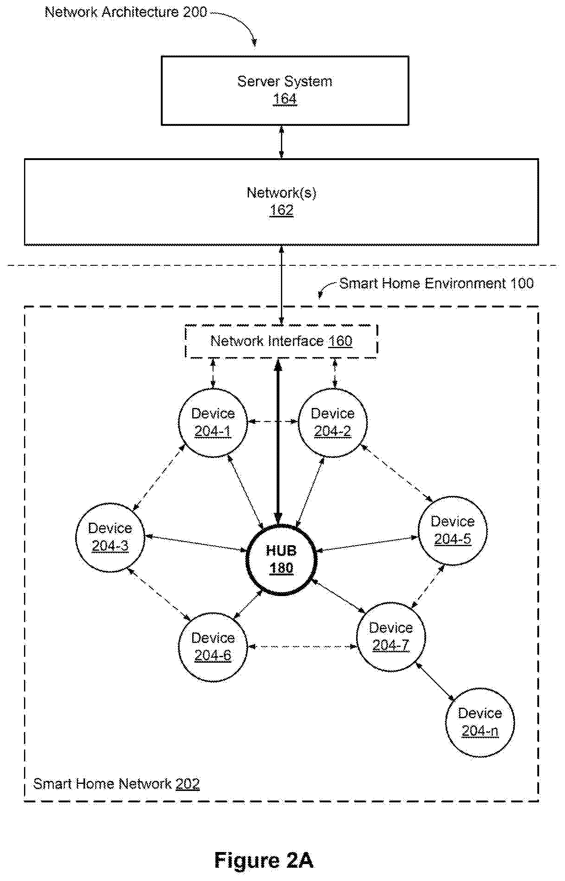
[0011] FIG. 2A is a block diagram illustrating a representative network architecture that includes a smart home network in accordance with some implementations.
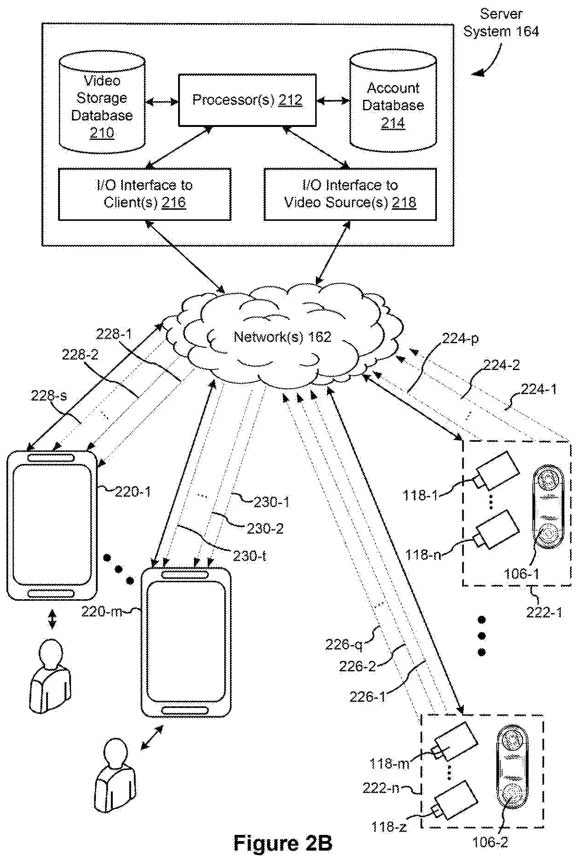
[0012] FIG. 2B is a representative operating environment in which a server system interacts with client devices and smart devices in accordance with some implementations.
[0013] FIG. 3A is a block diagram illustrating a representative server system, in accordance with some implementations.
[0014] FIG. 3B illustrates various data structures used by some implementations.
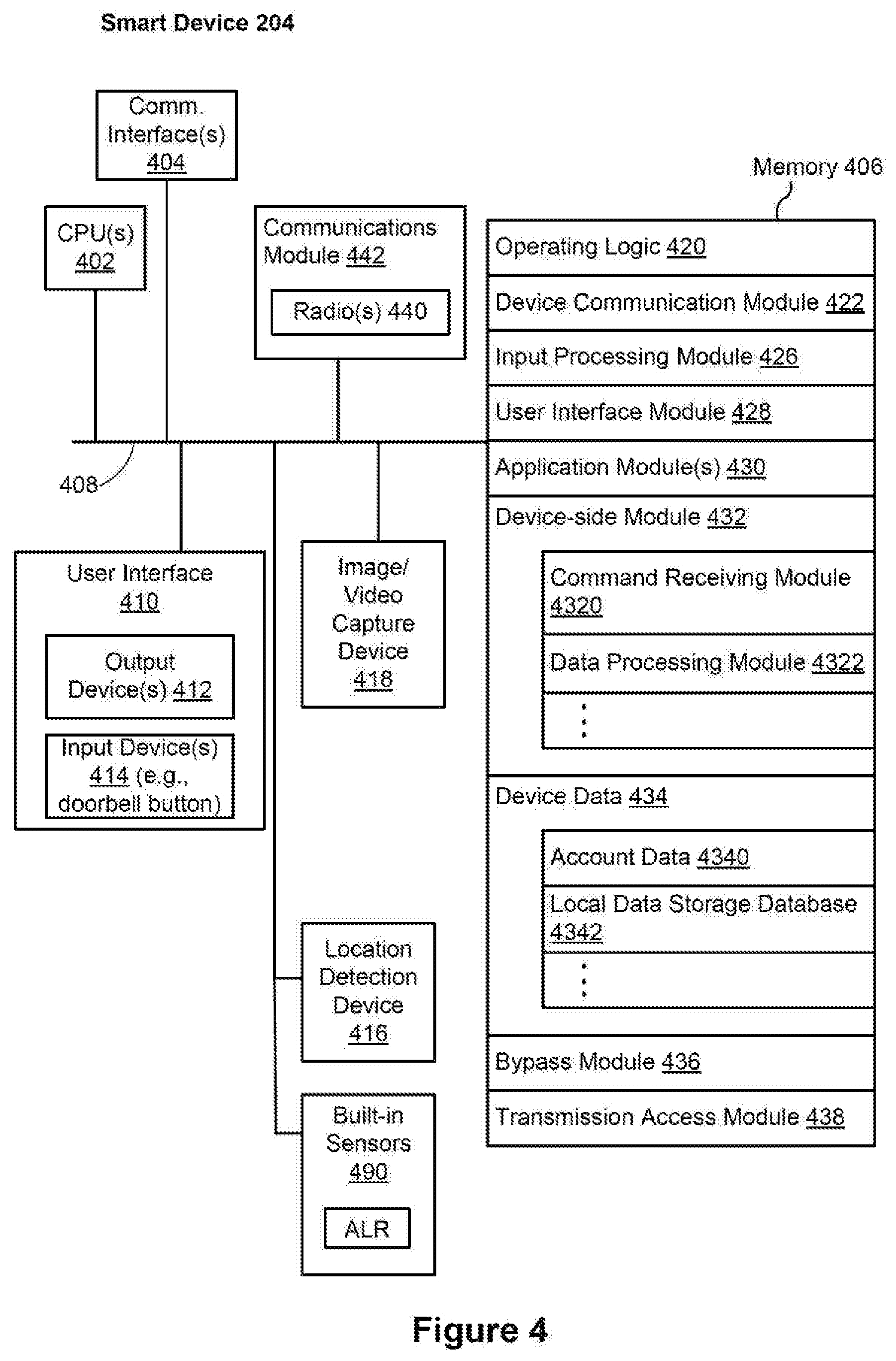
[0015] FIG. 4 is a block diagram illustrating a representative smart device, e.g., a doorbell camera, in accordance with some implementations.
[0016] FIG. 5 illustrates a representative system architecture for video analysis and categorization, in accordance with some implementations.
[0017] FIG. 6 is a block diagram illustrating a representative client device, in accordance with some implementations.
[0018] FIGS. 7A and 7B are a front view and a rear view of a doorbell camera in accordance with some implementations, respectively.
[0019] FIG. 8 is a schematic block diagram of a doorbell camera system in accordance with some implementations.
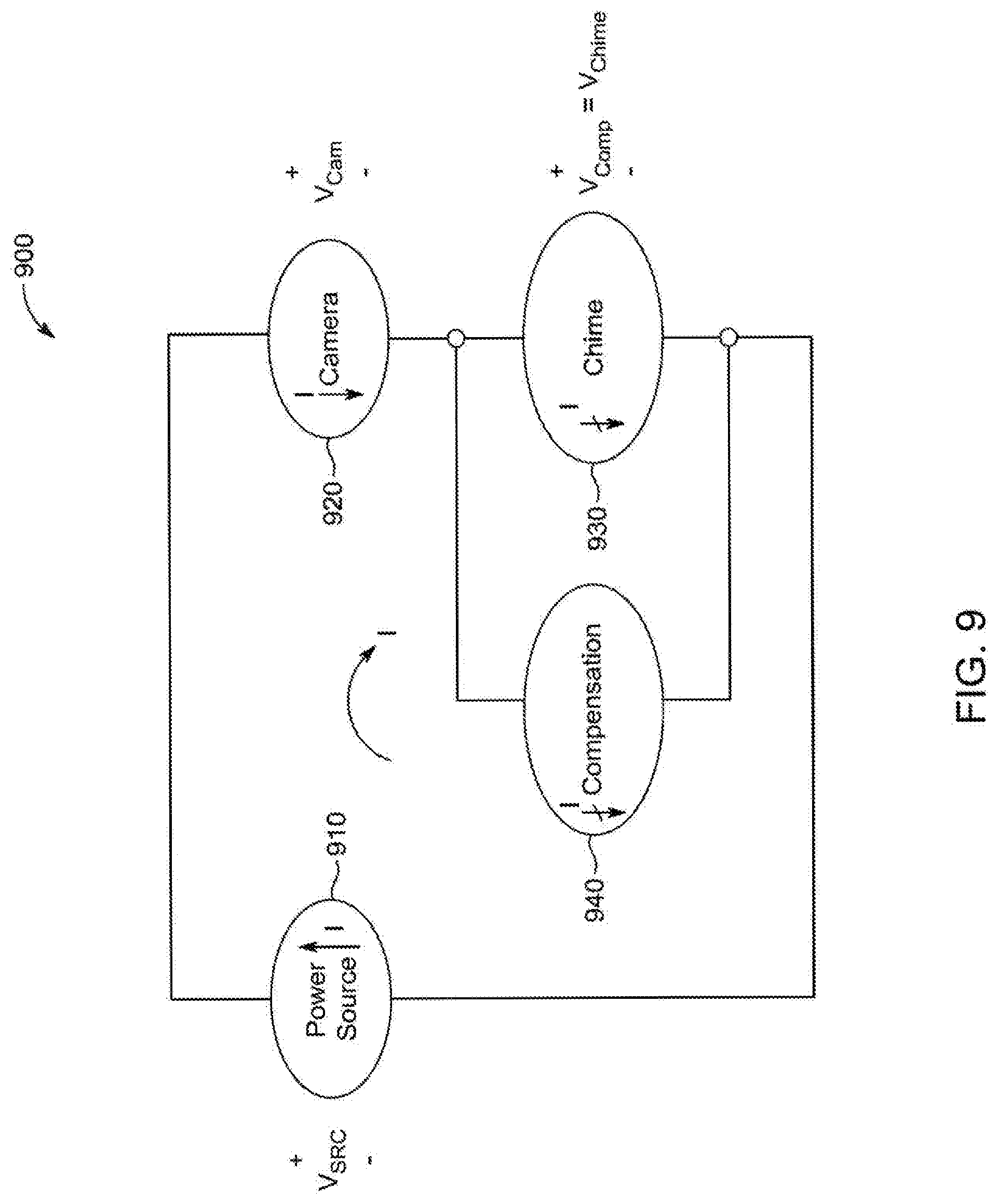
[0020] FIG. 9 shows an illustrative current diagram of a doorbell system in accordance with some implementations.
[0021] FIG. 10 shows an illustrative schematic diagram of doorbell system in accordance with some implementations.
[0022] FIG. 11 shows an illustrative timing diagram showing current consumption of various components within a doorbell system according to an embodiment.
[0023] FIG. 12 shows an illustrative current compensation network embodiment that can be used in connection with a doorbell system according to an embodiment.
[0024] FIG. 13 shows an illustrative current compensation network embodiment that can be used in connection with a doorbell system according to an embodiment.
[0025] FIG. 14 shows an illustrative current compensation network embodiment that can be used in connection with a doorbell system according to an embodiment.
[0026] Like reference numerals refer to corresponding parts throughout the several views of the drawings.
DESCRIPTION OF IMPLEMENTATIONS
[0027] In the following detailed description, for purposes of explanation, numerous specific details are set forth to provide a thorough understanding of the various embodiments. Those of ordinary skill in the art will realize that these various embodiments are illustrative only and are not intended to be limiting in any way. Other embodiments will readily suggest themselves to such skilled persons having the benefit of this disclosure.
[0028] In addition, for clarity purposes, not all of the routine features of the embodiments described herein are shown or described. One of ordinary skill in the art would readily appreciate that in the development of any such actual embodiment, numerous embodiment-specific decisions may be required to achieve specific design objectives. These design objectives will vary from one embodiment to another and from one developer to another. Moreover, it will be appreciated that such a development effort might be complex and time-consuming but would nevertheless be a routine engineering undertaking for those of ordinary skill in the art having the benefit of this disclosure.
[0029] FIG. 1 is an example smart home environment 100 in accordance with some implementations. The smart home environment 100 includes a structure 150 (e.g., a house, office building, garage, or mobile home) with various integrated devices. It will be appreciated that devices may also be integrated into a smart home environment 100 that does not include an entire structure 150, such as an apartment, condominium, or office space. Further, the smart home environment 100 may control and/or be coupled to devices outside of the actual structure 150. Indeed, several devices in the smart home environment 100 need not be physically within the structure 150. For example, a device controlling a pool heater 114 or irrigation system 116 may be located outside of the structure 150.
[0030] It is to be appreciated that "smart home environments" may refer to smart environments for homes such as a single-family house, but the scope of the present teachings is not so limited. The present teachings are also applicable, without limitation, to duplexes, townhomes, multi-unit apartment buildings, hotels, retail stores, office buildings, industrial buildings, and more generally any living space or work space.
[0031] It is also to be appreciated that while the terms user, customer, installer, homeowner, occupant, guest, tenant, landlord, repair person, and the like may be used to refer to the person or persons acting in the context of some particularly situations described herein, these references do not limit the scope of the present teachings with respect to the person or persons who are performing such actions. Thus, for example, the terms user, customer, purchaser, installer, subscriber, and homeowner may often refer to the same person in the case of a single-family residential dwelling, because the head of the household is often the person who makes the purchasing decision, buys the unit, and installs and configures the unit, and is also one of the users of the unit. However, in other scenarios, such as a landlord-tenant environment, the customer may be the landlord with respect to purchasing the unit, the installer may be a local apartment supervisor, a first user may be the tenant, and a second user may again be the landlord with respect to remote control functionality. Importantly, while the identity of the person performing the action may be germane to a particular advantage provided by one or more of the implementations, such identity should not be construed in the descriptions that follow as necessarily limiting the scope of the present teachings to those particular individuals having those particular identities.
[0032] The depicted structure 150 includes a plurality of rooms 152, separated at least partly from each other via walls 154. The walls 154 may include interior walls or exterior walls. Each room may further include a floor 156 and a ceiling 158. Devices may be mounted on, integrated with and/or supported by a wall 154, floor 156 or ceiling 158.
[0033] In some implementations, the integrated devices of the smart home environment 100 include intelligent, multi-sensing, network-connected devices that integrate seamlessly with each other in a smart home network (e.g., 202 FIG. 2A) and/or with a central server or a cloud-computing system to provide a variety of useful smart home functions. The smart home environment 100 may include one or more intelligent, multi-sensing, network-connected thermostats 102 (hereinafter referred to as "smart thermostats 102"), one or more intelligent, network-connected, multi-sensing hazard detection units 104 (hereinafter referred to as "smart hazard detectors 104"), one or more intelligent, multi-sensing, network-connected entryway interface devices 106 and 120 (hereinafter referred to as "smart doorbells 106" and "smart door locks 120"), and one or more intelligent, multi-sensing, network-connected alarm systems 122 (hereinafter referred to as "smart alarm systems 122").
[0034] In some implementations, the one or more smart thermostats 102 detect ambient climate characteristics (e.g., temperature and/or humidity) and control a HVAC system 103 accordingly. For example, a respective smart thermostat 102 includes an ambient temperature sensor.
[0035] The one or more smart hazard detectors 104 may include thermal radiation sensors directed at respective heat sources (e.g., a stove, oven, other appliances, a fireplace, etc.). For example, a smart hazard detector 104 in a kitchen 153 includes a thermal radiation sensor directed at a stove/oven 112. A thermal radiation sensor may determine the temperature of the respective heat source (or a portion thereof) at which it is directed and may provide corresponding blackbody radiation data as output.
[0036] The smart doorbell 106 and/or the smart door lock 120 may detect a person's approach to or departure from a location (e.g., an outer door), control doorbell/door locking functionality (e.g., receive user inputs from a portable electronic device 166-1 to actuate bolt of the smart door lock 120), announce a person's approach or departure via audio or visual means, and/or control settings on a security system (e.g., to activate or deactivate the security system when occupants go and come). In some implementations, the smart doorbell 106 includes some or all of the components and features of the camera 118. In some implementations, the smart doorbell 106 includes a camera 118, and therefore, is also called "doorbell camera 106" in this application.
[0037] The smart alarm system 122 may detect the presence of an individual within close proximity (e.g., using built-in IR sensors), sound an alarm (e.g., through a built-in speaker, or by sending commands to one or more external speakers), and send notifications to entities or users within/outside of the smart home network 100. In some implementations, the smart alarm system 122 also includes one or more input devices or sensors (e.g., keypad, biometric scanner, NFC transceiver, microphone) for verifying the identity of a user, and one or more output devices (e.g., display, speaker). In some implementations, the smart alarm system 122 may also be set to an "armed" mode, such that detection of a trigger condition or event causes the alarm to be sounded unless a disarming action is performed.
[0038] In some implementations, the smart home environment 100 includes one or more intelligent, multi-sensing, network-connected wall switches 108 (hereinafter referred to as "smart wall switches 108"), along with one or more intelligent, multi-sensing, network-connected wall plug interfaces 110 (hereinafter referred to as "smart wall plugs 110"). The smart wall switches 108 may detect ambient lighting conditions, detect room-occupancy states, and control a power and/or dim state of one or more lights. In some instances, smart wall switches 108 may also control a power state or speed of a fan, such as a ceiling fan. The smart wall plugs 110 may detect occupancy of a room or enclosure and control supply of power to one or more wall plugs (e.g., such that power is not supplied to the plug if nobody is at home).
[0039] In some implementations, the smart home environment 100 of FIG. 1 includes a plurality of intelligent, multi-sensing, network-connected appliances 112 (hereinafter referred to as "smart appliances 112"), such as refrigerators, stoves, ovens, televisions, washers, dryers, lights, stereos, intercom systems, garage-door openers, floor fans, ceiling fans, wall air conditioners, pool heaters, irrigation systems, security systems, space heaters, window AC units, motorized duct vents, and so forth. In some implementations, when plugged in, an appliance may announce itself to the smart home network, such as by indicating what type of appliance it is, and it may automatically integrate with the controls of the smart home. Such communication by the appliance to the smart home may be facilitated by either a wired or wireless communication protocol. The smart home may also include a variety of non-communicating legacy appliances 140, such as old conventional washer/dryers, refrigerators, and the like, which may be controlled by smart wall plugs 110. The smart home environment 100 may further include a variety of partially communicating legacy appliances 142, such as infrared ("IR") controlled wall air conditioners or other IR-controlled devices, which may be controlled by IR signals provided by the smart hazard detectors 104 or the smart wall switches 108.
[0040] In some implementations, the smart home environment 100 includes one or more network-connected cameras 118 that are configured to provide video monitoring and security in the smart home environment 100. The cameras 118 may be used to determine occupancy of the structure 150 and/or particular rooms 152 in the structure 150, and thus may act as occupancy sensors. For example, video captured by the cameras 118 may be processed to identify the presence of an occupant in the structure 150 (e.g., in a particular room 152). Specific individuals may be identified based, for example, on their appearance (e.g., height, face) and/or movement (e.g., their walk/gait). Cameras 118 may additionally include one or more sensors (e.g., IR sensors, motion detectors), input devices (e.g., microphone for capturing audio), and output devices (e.g., speaker for outputting audio). In some implementations, the cameras 118 are each configured to operate in a day mode and in a low-light mode (e.g., a night mode). In some implementations, the cameras 118 each include one or more IR illuminators for providing illumination while the camera is operating in the low-light mode. In some implementations, the cameras 118 include one or more outdoor cameras. In some implementations, the outdoor cameras include additional features and/or components such as weatherproofing and/or solar ray compensation.
[0041] The smart home environment 100 may additionally or alternatively include one or more other occupancy sensors (e.g., the smart doorbell 106, smart door locks 120, touch screens, IR sensors, microphones, ambient light sensors, motion detectors, smart nightlights 170, etc.). In some implementations, the smart home environment 100 includes radio-frequency identification (RFID) readers (e.g., in each room 152 or a portion thereof) that determine occupancy based on RFID tags located on or embedded in occupants. For example, RFID readers may be integrated into the smart hazard detectors 104.
[0042] The smart home environment 100 may also include communication with devices outside of the physical home but within a proximate geographical range of the home. For example, the smart home environment 100 may include a pool heater monitor 114 that communicates a current pool temperature to other devices within the smart home environment 100 and/or receives commands for controlling the pool temperature. Similarly, the smart home environment 100 may include an irrigation monitor 116 that communicates information regarding, irrigation systems within the smart home environment 100 and/or receives control information for controlling such irrigation systems.
[0043] By virtue of network connectivity, one or more of the smart home devices of Figure I may further allow a user to interact with the device even if the user is not proximate to the device. For example, a user may communicate with a device using a computer (e.g., a desktop computer, laptop computer, or tablet) or other portable electronic device 166 (e.g., a mobile phone, such as a smart phone). A webpage or application may be configured to receive communications from the user and control the device based on the communications and/or to present information about the device's operation to the user. For example, the user may view a current set point temperature for a device (e.g., a stove) and adjust it using a computer. The user may be in the structure during this remote communication or outside the structure.
[0044] As discussed above, users may control smart devices in the smart home environment 100 using a network-connected computer or portable electronic device 166. In some examples, some or all of the occupants (e.g., individuals who live in the home) may register their device 166 with the smart home environment 100. Such registration may be made at a central server to authenticate the occupant and/or the device as being associated with the home and to give permission to the occupant to use the device to control the smart devices in the home. An occupant may use their registered device 166 to remotely control the smart devices of the home, such as when the occupant is at work or on vacation. The occupant may also use their registered device to control the smart devices when the occupant is actually located inside the home, such as when the occupant is sitting on a couch inside the home. It should be appreciated that instead of or in addition to registering devices 166, the smart home environment 100 may make inferences about which individuals live in the home and are therefore occupants and which devices 166 are associated with those individuals. As such, the smart home environment may "learn" who is an occupant and permit the devices 166 associated with those individuals to control the smart devices of the home.
[0045] In some implementations, in addition to containing processing and sensing capabilities, devices 102, 104, 106, 108, 110, 112, 114, 116, 118, 120, and/or 122 (collectively referred to as "the smart devices") are capable of data communications and information sharing with other smart devices, a central server or cloud-computing system, and/or other devices that are network-connected. Data communications may be carried out using any of a variety of custom or standard wireless protocols (e.g., IEEE 802.15.4, ZigBee, 6LoWPAN, Thread, Z-Wave, Bluetooth Smart, ISA100.5A, WirelessHART, MiWi, etc.) and/or any of a variety of custom or standard wired protocols (e.g., Ethernet, HomePlug, etc.), or any other suitable communication protocol, including communication protocols not yet developed as of the filing date of this document.
[0046] In some implementations, the smart devices serve as wireless or wired repeaters. In some implementations, a first one of the smart devices communicates with a second one of the smart devices via a wireless router. The smart devices may further communicate with each other via a connection (e.g., network interface 160) to a network, such as the Internet 162. Through the Internet 162, the smart devices may communicate with a server system 164 (also called a central server system and/or a cloud-computing system herein). The server system 164 may be associated with a manufacturer, support entity, or service provider associated with the smart device(s). In some implementations, a user is able to contact customer support using a smart device itself rather than needing to use other communication means, such as a telephone or Internet-connected computer. In some implementations, software updates are automatically sent from the server system 164 to smart devices (e.g., when available, when purchased, or at routine intervals).
[0047] In some implementations, the network interface 160 includes a conventional network device (e.g., a router), and the smart home environment 100 of FIG. 1 includes a hub device 180 that is communicatively coupled to the network(s) 162 directly or via the network interface 160. The hub device 180 is further communicatively coupled to one or more of the above intelligent, multi-sensing, network-connected devices (e.g., smart devices of the smart home environment 100). Each of these smart devices optionally communicates with the hub device 180 using one or more radio communication networks available at least in the smart home environment 100 (e.g., ZigBee, Z-Wave, Insteon, Bluetooth, Wi-Fi and other radio communication networks). In some implementations, the hub device 180 and devices coupled with/to the hub device can be controlled and/or interacted with via an application running on a smart phone, household controller, laptop, tablet computer, game console or similar electronic device. In some implementations, a user of such controller application can view status of the hub device or coupled smart devices, configure the hub device to interoperate with smart devices newly introduced to the home network, commission new smart devices, and adjust or view settings of connected smart devices, etc. In some implementations the hub device extends capabilities of low capability smart device to match capabilities of the highly capable smart devices of the same type, integrates functionality of multiple different device types--even across different communication protocols, and is configured to streamline adding of new devices and commissioning of the hub device. In some implementations, hub device 180 further includes a local storage device for storing data related to, or output by, smart devices of smart home environment 100. In some implementations, the data includes one or more of: video data output by a camera device, metadata output by a smart device, settings information for a smart device, usage logs for a smart device, and the like.
[0048] In some implementations, smart home environment 100 includes a local storage device 190 for storing data related to, or output by, smart devices of smart home environment 100. In some implementations, the data includes one or more of: video data output by a camera device (e.g., camera 118 or doorbell camera 106), metadata output by a smart device, settings information for a smart device, usage logs for a smart device, and the like. In some implementations, local storage device 190 is communicatively coupled to one or more smart devices via a smart home network (e.g., smart home network 202, FIG. 2A). In some implementations, local storage device 190 is selectively coupled to one or more smart devices via a wired and/or wireless communication network. In some implementations, local storage device 190 is used to store video data when external network conditions are poor. For example, local storage device 190 is used when an encoding bitrate of camera 118 exceeds the available bandwidth of the external network (e.g., network(s) 162). In some implementations, local storage device 190 temporarily stores video data from one or more cameras (e.g., camera 118) prior to transferring the video data to a server system (e.g., server system 164).
[0049] In accordance with various implementations of the application, a doorbell camera 106 integrates a camera 118 in a smart doorbell device 106. The doorbell camera 106 has a doorbell button, a camera module, a processor and memory including programs executed by the processor, and is electrically coupled to a remote chime device that rings in response to a user press on the doorbell button. The doorbell camera 106 operates at a first camera mode and a second camera mode. In both of these two modes, the doorbell camera 106 continuously records video information from a field of view of the doorbell camera 106, and communicates with a remote server 164 to receive instructions from and/or upload the recorded video information to the remote server 164. More importantly, the doorbell camera 106 is configured to detect whether there is a user press on the doorbell button. In accordance with a determination that no user press is being applied on the doorbell button, the first camera mode is activated to bypass the remote chime device and couple the camera module of the doorbell camera 106 to a remote transformer for receiving a power supply therefrom. Conversely, in accordance with a determination that a user press is being applied on the doorbell button, the second doorbell mode is activated to couple both the camera module of the doorbell camera 106 and the remote chime device to the remote transformer. For example, the camera module and the remote chimer device are electrically coupled in series and both powered by the remote transformer at the second doorbell mode, thereby enabling the remote chime device to ring concurrently while the camera module is recording the video information. In some implementations, while the doorbell button is being pressed (i.e., at a second doorbell mode), the camera module of the doorbell camera 106 is electrically decoupled from the transformer, and relies on the battery to provide needed power. The battery is recharged at the first camera mode when the button is not pressed. The battery needs to be sized to be sufficiently large so that it can charge back up in between button presses. In some implementations, the doorbell button of the doorbell camera 106 is configured to sustain a predetermined number (e.g., 100) of continuous presses without losing battery power.
[0050] In some implementations, the doorbell camera 106 is located at a door of a structure 150, and the remote chime device and the transformer are located in two separate rooms 152 (e.g., in a kitchen 153 and a garage, respectively).
[0051] In some implementations, the doorbell camera 106 continues to operate as a standard doorbell (i.e., ring the remote chime device in response to a user press on the doorbell button), independently of whether the camera module of the doorbell camera 106 functions properly. For example, in some situations, the doorbell camera 106 loses connection to any local or wide area network. The camera module is disabled from capturing images and sharing the captured images with the remote server 164 or any client device 166, and however, the doorbell camera 106 still responds properly to the user press on its doorbell button.
[0052] Additionally, in some implementations, video and audio recording functions of the doorbell camera 106 are configured to comply with local laws and regulations that are enforced in different jurisdictions concerning recording video and audio information in public places without consent of those being recorded. The doorbell camera 106 is pre-programmed to comply with such laws and regulations in a factory, before it is shipped to a specific jurisdiction.
[0053] FIG. 2A is a block diagram illustrating a representative network architecture 200 that includes a smart home network 202 in accordance with some implementations. In some implementations, the smart devices 204 in the smart home environment 100 (e.g., devices 102, 104, 106, 108, 110, 112, 114, 116, 118, 120, and/or 122) combine with the hub device 180 to create a mesh network in smart home network 202. In some implementations, one or more smart devices 204 in the smart home network 202 operate as a smart home controller. Additionally and/or alternatively, hub device 180 operates as the smart home controller. In some implementations, a smart home controller has more computing power than other smart devices. In some implementations, a smart home controller processes inputs (e.g., from smart devices 204, electronic device 166, and/or server system 164) and sends commands (e.g., to smart devices 204 in the smart home network 202) to control operation of the smart home environment 100. In some implementations, some of the smart devices 204 in the smart home network 202 (e.g., in the mesh network) are "spokesman" nodes (e.g., 204-1) and others are "low-powered" nodes (e.g., 204-9). Some of the smart devices in the smart home environment 100 are battery powered, while others have a regular and reliable power source, such as by connecting to wiring (e.g., to 120V or 240V line voltage wires) behind the walls 154 of the smart home environment. The smart devices that have a regular and reliable power source are referred to as "spokesman" nodes. These nodes are typically equipped with the capability of using a wireless protocol to facilitate bidirectional communication with a variety of other devices in the smart home environment 100, as well as with the server system 164. In some implementations, one or more "spokesman" nodes operate as a smart home controller. On the other hand, the devices that are battery powered are the "low-power-nodes. These nodes tend to be smaller than spokesman nodes and typically only communicate using wireless protocols that require very little power, such as Zigbee, ZWave, 6LoWPAN, Thread, Bluetooth, etc.
[0054] In some implementations, some low-power nodes are incapable of bidirectional communication. These low-power nodes send messages, but they are unable to "listen." Thus, other devices in the smart home environment 100, such as the spokesman nodes, cannot send information to these low-power nodes.
[0055] In some implementations, some low-power nodes are capable of only a limited bidirectional communication. For example, other devices are able to communicate with the low-power nodes only during a certain time period.
[0056] As described, in some implementations, the smart devices serve as low-power and spokesman nodes to create a mesh network in the smart home environment 100. In some implementations, individual low-power nodes in the smart home environment regularly send out messages regarding what they are sensing, and the other low-powered nodes in the smart home environment--in addition to sending out their own messages--forward the messages, thereby causing the messages to travel from node to node (i.e., device to device) throughout the smart home network 202. In some implementations, the spokesman nodes in the smart home network 202, which are able to communicate using a relatively high-power communication protocol, such as IEEE 802.11, are able to switch to a relatively low-power communication protocol, such as IEEE 802.15.4, to receive these messages, translate the messages to other communication protocols, and send the translated messages to other spokesman nodes and/or the server system 164 (using, e.g., the relatively high-power communication protocol). Thus, the low-powered nodes using low-power communication protocols are able to send and/or receive messages across the entire smart home network 202, as well as over the Internet 162 to the server system 164. In some implementations, the mesh network enables the server system 164 to regularly receive data from most or all of the smart devices in the home, make inferences based on the data, facilitate state synchronization across devices within and outside of the smart home network 202, and send commands to one or more of the smart devices to perform tasks in the smart home environment.
[0057] As described, the spokesman nodes and some of the low-powered nodes are capable of "listening." Accordingly, users, other devices, and/or the server system 164 may communicate control commands to the low-powered nodes. For example, a user may use the electronic device 166 (e.g., a smart phone) to send commands over the Internet to the server system 164, which then relays the commands to one or more spokesman nodes in the smart home network 202. The spokesman nodes may use a low-power protocol to communicate the commands to the low-power nodes throughout the smart home network 202, as well as to other spokesman nodes that did not receive the commands directly from the server system 164.
[0058] In some implementations, a smart nightlight 170 (FIG. 1), which is an example of a smart device 204, is a low-power node. In addition to housing a light source, the smart nightlight 170 houses an occupancy sensor, such as an ultrasonic or passive IR sensor, and an ambient light sensor, such as a photo resistor or a single-pixel sensor that measures light in the room. In some implementations, the smart nightlight 170 is configured to activate the light source when its ambient light sensor detects that the room is dark and when its occupancy sensor detects that someone is in the room. In other implementations, the smart nightlight 170 is simply configured to activate the light source when its ambient light sensor detects that the room is dark. Further, in some implementations, the smart nightlight 170 includes a low-power wireless communication chip (e.g., a ZigBee chip) that regularly sends out messages regarding the occupancy of the room and the amount of light in the room, including instantaneous messages coincident with the occupancy sensor detecting the presence of a person in the room. As mentioned above, these messages may be sent wirelessly (e.g., using the mesh network) from node to node (i.e., smart device to smart device) within the smart home network 202 as well as over the Internet 162 to the server system 164.
[0059] Other examples of low-power nodes include battery-operated versions of the smart hazard detectors 104. These smart hazard detectors 104 are often located in an area without access to constant and reliable power and may include any number and type of sensors, such as smoke/fire/heat sensors (e.g., thermal radiation sensors), carbon monoxide/dioxide sensors, occupancy/motion sensors, ambient light sensors, ambient temperature sensors, humidity sensors, and the like. Furthermore, smart hazard detectors 104 may send messages that correspond to each of the respective sensors to the other devices and/or the server system 164, such as by using the mesh network as described above.
[0060] Examples of spokesman nodes include smart doorbells 106, smart thermostats 102, smart wall switches 108, and smart wall plugs 110. These devices are often located near and connected to a reliable power source, and therefore may include more power-consuming components, such as one or more communication chips capable of bidirectional communication in a variety of protocols.
[0061] In some implementations, the smart home environment 100 includes service robots 168 (FIG. 1) that are configured to carry out, in an autonomous manner, any of a variety of household tasks.
[0062] As explained above with reference to FIG. 1, in some implementations, the smart home environment 100 of FIG. 1 includes a hub device 180 that is communicatively coupled to the network(s) 162 directly or via the network interface 160. The hub device 180 is further communicatively coupled to one or more of the smart devices using a radio communication network that is available at least in the smart home environment 100. Communication protocols used by the radio communication network include, but are not limited to, ZigBee, Z-Wave, Insteon, EuOcean, Thread, OSIAN, Bluetooth Low Energy and the like. In some implementations, the hub device 180 not only converts the data received from each smart device to meet the data format requirements of the network interface 160 or the network(s) 162, but also converts information received from the network interface 160 or the network(s) 162 to meet the data format requirements of the respective communication protocol associated with a targeted smart device. In some implementations, in addition to data format conversion, the hub device 180 further processes the data received from the smart devices or information received from the network interface 160 or the network(s) 162 preliminary. For example, the hub device 180 can integrate inputs from multiple sensors/connected devices (including sensors/devices of the same and/or different types), perform higher level processing on those inputs--e.g., to assess the overall environment and coordinate operation among the different sensors/devices--and/or provide instructions to the different devices based on the collection of inputs and programmed processing. It is also noted that in some implementations, the network interface 160 and the hub device 180 are integrated to one network device. Functionality described herein is representative of particular implementations of smart devices, control application(s) running on representative electronic device(s) (such as a smart phone), hub device(s) 180, and server(s) coupled to hub device(s) via the Internet or other Wide Area Network. All or a portion of this functionality and associated operations can be performed by any elements of the described system--for example, all or a portion of the functionality described herein as being performed by an implementation of the hub device can be performed, in different system implementations, in whole or in part on the server, one or more connected smart devices and/or the control application, or different combinations thereof.
[0063] FIG. 2B illustrates a representative operating environment in which a server system 164 provides data processing for monitoring and facilitating review of events (e.g., motion, audio, security, etc.) in video streams captured by video cameras 118 or doorbell cameras 106. As shown in FIG. 2B, the server system 164 receives video data from video sources 222 (including cameras 118 or doorbell cameras 106) located at various physical locations (e.g., inside homes, restaurants, stores, streets, parking lots, and/or the smart home environments 100 of FIG. 1). Each video source 222 may be bound to one or more reviewer accounts, and the server system 164 provides video monitoring data for the video source 222 to client devices 220 associated with the reviewer accounts. For example, the portable electronic device 166 is an example of the client device 220. In some implementations, the server system 164 is a video processing server that provides video processing services to video sources and client devices 220.
[0064] In some implementations, each of the video sources 222 includes one or more video cameras 118 or doorbell cameras 106 that capture video and send the captured video to the server system 164 substantially in real-time. In some implementations, each of the video sources 222 includes a controller device (not shown) that serves as an intermediary between the one or more cameras and the server system 164. The controller device receives the video data from the one or more cameras, optionally performs some preliminary processing on the video data, and sends the video data to the server system 164 on behalf of the one or more cameras substantially in real-time. In some implementations, each camera has its own on-board processing capabilities to perform some preliminary processing on the captured video data before sending the processed video data (along with metadata obtained through the preliminary processing) to the controller device and/or the server system 164.
[0065] In accordance with some implementations, each of the client devices 220 includes a client-side module. The client-side module communicates with a server-side module executed on the server system 164 through the one or more networks 162. The client-side module provides client-side functionality for the event monitoring and review processing and communications with the server-side module. The server-side module provides server-side functionality for event monitoring and review processing for any number of client-side modules each residing on a respective client device 220. The server-side module also provides server-side functionality for video processing and camera control for any number of the video sources 222, including any number of control devices and the cameras.
[0066] In some implementations, the server system 164 includes one or more processors 212, a video storage database 210, an account database 214, an I/O interface to one or more client devices 216, and an I/O interface to one or more video sources 218. The I/O interface to one or more clients 216 facilitates the client-facing input and output processing. The account database 214 stores a plurality of profiles for reviewer accounts registered with the video processing server, where a respective user profile includes account credentials for a respective reviewer account, and one or more video sources linked to the respective reviewer account. The I/O interface to one or more video sources 218 facilitates communications with one or more video sources 222 (e.g., groups of one or more cameras and associated controller devices). The video storage database 210 stores raw video data received from the video sources 222, as well as various types of metadata, such as motion events, event categories, event category models, event filters, and event masks, for use in data processing for event monitoring and review for each reviewer account.
[0067] Examples of a representative client device 220 include a handheld computer, a wearable computing device, a personal digital assistant (PDA), a tablet computer, a laptop computer, a desktop computer, a cellular telephone, a smart phone, an enhanced general packet radio service (EGPRS) mobile phone, a media player, a navigation device, a game console, a television, a remote control, a point-of-sale (POS) terminal, a vehicle-mounted computer, an ebook reader, or a combination of any two or more of these data processing devices or other data processing devices.
[0068] Examples of the one or more networks 162 include local area networks (LAN) and wide area networks (WAN) such as the Internet. The one or more networks 162 are implemented using any known network protocol, including various wired or wireless protocols, such as Ethernet, Universal Serial Bus (USB), FIREWIRE, Long Term Evolution (LTE), Global System for Mobile Communications (GSM), Enhanced Data. GSM Environment (EDGE), code division multiple access (CDMA), time division multiple access (TDMA), Bluetooth, Wi-Fi, voice over Internet Protocol (VoIP), Wi-MAX, or any other suitable communication protocol.
[0069] In some implementations, the server system 164 is implemented on one or more standalone data processing apparatuses or a distributed network of computers. In some implementations, the server system 164 also employs various virtual devices and/or services of third party service providers (e.g., third-party cloud service providers) to provide the underlying computing resources and/or infrastructure resources of the server system 164. In some implementations, the server system 164 includes, but is not limited to, a server computer, a handheld computer, a tablet computer, a laptop computer, a desktop computer, or a combination of any two or more of these data processing devices or other data processing devices.
[0070] The server-client environment shown in FIG. 2B includes both a client-side portion (e.g., the client-side module) and a server-side portion (e.g., the server-side module). The division of functionality between the client and server portions of operating environment can vary in different implementations. Similarly, the division of functionality between a video source 222 and the server system 164 can vary in different implementations. For example, in some implementations, the client-side module is a thin-client that provides only user-facing input and output processing functions, and delegates all other data processing functionality to a backend server (e.g., the server system 164). Similarly, in some implementations, a respective one of the video sources 222 is a simple video capturing device that continuously captures and streams video data to the server system 164 with limited or no local preliminary processing on the video data. Although many aspects of the present technology are described from the perspective of the server system 164, the corresponding actions performed by a client device 220 and/or the video sources 222 would be apparent to one of skill in the art. Similarly, some aspects of the present technology may be described from the perspective of a client device or a video source, and the corresponding actions performed by the video server would be apparent to one of skill in the art. Furthermore, some aspects of the present technology may be performed by the server system 164, a client device 220, and a video source 222 cooperatively.
[0071] In some implementations, a video source 222 (e.g., a camera 118 or 106) transmits one or more streams of video data to the server system 164. In some implementations, the one or more streams may include multiple streams, of respective resolutions and/or frame rates, of the raw video captured by the camera 118 or 106. In some implementations, the multiple streams may include a "primary" stream with a certain resolution and frame rate, corresponding to the raw video captured by the camera 118 or 106, and one or more additional streams. An additional stream may be the same video stream as the "primary" stream but at a different resolution and/or frame rate, or a stream that captures a portion of the "primary" stream (e.g., cropped to include a portion of the field of view or pixels of the primary stream) at the same or different resolution and/or frame rate as the "primary" stream.
[0072] In some implementations, one or more of the streams are sent from the video source 222 directly to a client device 220 (e.g., without being routed to, or processed by, the server system 164). In some implementations, one or more of the streams is stored at the camera 118 or 106 (e.g., in memory 406, FIG. 4) and/or a local storage device (e.g., a dedicated recording device), such as a digital video recorder (DVR). For example, in accordance with some implementations, the camera 118 or 106 stores the most recent 24 hours of video footage recorded by the camera. In some implementations, portions of the one or more streams are stored at the camera 118 or 106 and/or the local storage device (e.g., portions corresponding to particular events or times of interest).
[0073] In some implementations, the server system 164 transmits one or more streams of video data to a client device 220 to facilitate event monitoring by a user. In some implementations, the one or more streams may include multiple streams, of respective resolutions and/or frame rates, of the same video feed. In some implementations, the multiple streams include a "primary" stream with a certain resolution and frame rate, corresponding to the video feed, and one or more additional streams. An additional stream may be the same video stream as the "primary" stream but at a different resolution and/or frame rate, or a stream that shows a portion of the "primary" stream (e.g., cropped to include portion of the field of view or pixels of the primary stream) at the same or different resolution and/or frame rate as the "primary" stream.
[0074] FIG. 3A is a block diagram illustrating the server system 164 in accordance with some implementations. The server system 164 typically includes one or more processing units (CPUs) 302, one or more network interfaces 304 (e.g., including an I/O interface to one or more client devices and an I/O interface to one or more electronic devices), memory 306, and one or more communication buses 308 for interconnecting these components (sometimes called a chipset). The memory 306 includes high-speed random access memory, such as DRAM, SRAM, DDR SRAM, or other random access solid state memory devices; and, optionally, includes non-volatile memory, such as one or more magnetic disk storage devices, one or more optical disk storage devices, one or more flash memory devices, or one or more other non-volatile solid state storage devices. The memory 306, optionally, includes one or more storage devices remotely located from one or more processing units 302. The memory 306, or alternatively the non-volatile memory within memory 306, includes a non-transitory computer readable storage medium. In some implementations, the memory 306, or the non-transitory computer readable storage medium of the memory 306, stores the following programs, modules, and data structures, or a subset or superset thereof: [0075] an operating system 310 including procedures for handling various basic system services and for performing hardware dependent tasks; [0076] a network communication module 312 for connecting the server system 164 to other systems and devices (e.g., client devices, electronic devices, and systems connected to one or more networks 162) via one or more network interfaces 304 (wired or wireless); [0077] a server-side module 314, which provides server-side functionalities for device control, data processing, and data review, including, but not limited to: [0078] a data receiving module 3140 for receiving data from electronic devices (e.g., video data from a camera 118 or 106, FIG. 1) via the hub device 180, and preparing the received data for further processing and storage in the data storage database 3160; [0079] a hub and device control module 3142 for generating and sending server-initiated control commands to modify operation modes of electronic devices (e.g., devices of a smart home environment 100), and/or receiving (e.g., from client devices 220) and forwarding user-initiated control commands to modify operation modes of the electronic devices; [0080] a data processing module 3144 for processing the data provided by the electronic devices, and/or preparing and sending processed data to a device for review (e.g., client devices 220 for review by a user), including, but not limited to: [0081] an event processor sub-module 3146 for processing event candidates and/or events within a received video stream (e.g., a video stream from cameras 118 or 106); [0082] an event categorizer sub-module 3148 for categorizing event candidates and/or events within the received video stream; and [0083] a user interface sub-module 3150 for communicating with a user (e.g., sending alerts, timeline events, etc. and receiving user edits and zone definitions and the like) [0084] a server database 316, including but not limited to: [0085] a data storage database 3160 for storing data associated with each electronic device (e.g., each camera) of each user account, as well as data processing models, processed data results, and other relevant metadata (e.g., names of data results, location of electronic device, creation time, duration, settings of the electronic device, etc.) associated with the data, where (optionally) all or a portion of the data and/or processing associated with the hub device 180 or smart devices are stored securely; [0086] an account database 3162 for storing account information for user accounts, including user account information such as user profiles 3163, information and settings for linked hub devices and electronic devices (e.g., hub device identifications), hub device specific secrets, relevant user and hardware characteristics (e.g., service tier, device model, storage capacity, processing capabilities, etc.), user interface settings, data review preferences, etc., where the information for associated electronic devices includes, but is not limited to, one or more device identifiers (e.g., MAC address and UUID), device specific secrets, and displayed titles; [0087] a device information database 3164 for storing device information related to one or more devices such as device profiles 3165, e.g., device identifiers and hub device specific secrets, independently of whether the corresponding hub devices have been associated with any user account; and [0088] an event information database 3166 for storing event information such as event records 3168, e.g., event log information, event categories, and the like.
[0089] Each of the above identified elements may be stored in one or more of the previously mentioned memory devices, and corresponds to a set of instructions for performing a function described above. The above identified modules or programs (i.e., sets of instructions) need not be implemented as separate software programs, procedures, or modules, and thus various subsets of these modules may be combined or otherwise rearranged in various implementations. In some implementations, the memory 306, optionally, stores a subset of the modules and data structures identified above. Furthermore, the memory 306, optionally, stores additional modules and data structures not described above.
[0090] FIG. 3B illustrates various data structures used by some implementations, including an event record 3168-i, a user profile 3163-i, and a device profile 3165-i. The event record 3168-i corresponds to an event i and data for the event i. In some instances, the data for motion event i includes event start data 31681 indicating when and/or how the event started, event segments data 31682, raw video data 31683, event end data 31684 indicating when and/or how the event ended, event features data 31685, scene features data 31686, associated user information 31687, and associated devices information 31688. In some instances, the event record 3168-i includes only a subset of the above data. In some instances, the event record 3168-i includes additional event data not shown such as data regarding event/motion masks.
[0091] The event start data 31681 includes date and time information such as a timestamp and optionally includes additional information such as information regarding the amount of motion present, a motion start location, amount of audio present, characteristics of the audio, and the like. Similarly, the event end data 31684 includes date and time information such as a timestamp and optionally includes additional information such as information regarding the amount of motion present, a motion start location, amount of audio present, characteristics of the audio, and the like.
[0092] The event segments 31682 includes information regarding segmentation of motion event i. In some instances, event segments are stored separately from the raw video data 31683. In some instances, the event segments are stored at a lower display resolution than the raw video data. For example, the event segments are optionally stored at 480p or 780p and the raw video data is stored at 1080i or 1080p. Storing the event segments at a lower display resolution enables the system to devote less time and resources to retrieving and processing the event segments. In some instances, the event segments are not stored separately and the segmentation information includes references to the raw video data 31683 as well as date and time information for reproducing the event segments. In some implementations, the event segments include one or more audio segments (e.g., corresponding to video segments).
[0093] The event features data 31685 includes information regarding event features such as event categorizations/classifications, object masks, motion masks, identified/recognized/tracked motion objects (also sometimes called blobs), information regarding features of the motion objects (e.g., object color, object dimensions, velocity, size changes, etc.), information regarding activity in zones of interest, and the like. The scene features data 31686 includes information regarding the scene in which the event took place such as depth map information, information regarding the location of windows, televisions, fans, the ceiling/floor, etc., information regarding whether the scene is indoors or outdoors, information regarding zones of interest, and the like. In some implementations, the event features data includes audio data, such as volume, pitch, characterizations, and the like.
[0094] The associated user information 31687 includes information regarding users associated with the event such as users identified in the event, users receiving notification of the event, and the like. In some instances, the associated user information 31687 includes a link, pointer, or reference to a user profile 3163 for to the user. The associated devices information 31688 includes information regarding the device or devices involved in the event (e.g., a camera 118 or 106 that recorded the event). In some instances, the associated devices information 31688 includes a link, pointer, or reference to a device profile 3165 for the device. In a specific example, the associated user information 31687 includes user identity of a visitor that has been recognized by the doorbell camera 106 when the visitor approaches the doorbell camera 106 and knocks at the door.
[0095] The user profile 3163-i corresponds to a user i associated with the smart home network (e.g., smart home network 202) such as a user of a hub device 204, a user identified by a hub device 204, a user who receives notifications from a hub device 204 or from the server system 164, and the like. In some instances, the user profile 3163-i includes user preferences 31631, user settings 31632, associated devices information 31633, and associated events information 31634. In some instances, the user profile 3163-i includes only a subset of the above data. In some instances, the user profile 3163-i includes additional user information not shown such as information regarding other users associated with the user i.
[0096] [The user preferences 31631 include explicit user preferences input by the user as well as implicit and/or inferred user preferences determined by the system (e.g., server system 164 and/or client device 220). In some instances, the inferred user preferences are based on historical user activity and/or historical activity of other users. The user settings 31632 include information regarding settings set by the user i such as notification settings, device settings, and the like. In some instances, the user settings 31632 include device settings for devices associated with the user i.
[0097] The associated devices information 31633 includes information regarding devices associated with the user i such as devices within the user's smart home environment 100 and/or client devices 220. In some instances, associated devices information 31633 includes a link, pointer, or reference to a corresponding device profile 3165. Associated events information 31634 includes information regarding events associated with user i such as events in which user i was identified, events for which user i was notified, events corresponding to user i's smart home environment 100, and the like. In some instances, the associated events information 31634 includes a link, pointer, or reference to a corresponding event record 3168.
[0098] The device profile 3165-i corresponds to a device i associated with a smart home network (e.g., smart home network 202) such a hub device 204, a camera 118 or 106, a client device 220, and the like. In some instances, the device profile 3165-i includes device settings 31651, associated devices information 31652, associated user information 31653, associated event information 31654, and environmental data 31655. In some instances, the device profile 3165-i includes only a subset of the above data. In some instances, the device profile 3165-i includes additional device information not shown such as information regarding whether the device is currently active.
[0099] The device settings 31651 include information regarding the current settings of device i such as positioning information, mode of operation information, and the like. In some instances, the device settings 31651 are user-specific and are set by respective users of the device i. The associated devices information 31652 includes information regarding other devices associated with device i such as other devices linked to device i and/or other devices in the same smart home network as device i. In some instances, the associated devices information 31652 includes a link, pointer, or reference to a respective device profile 3165 corresponding to the associated device.
[0100] The associated user information 31653 includes information regarding users associated with the device such as users receiving notifications from the device, users registered with the device, users associated with the smart home network of the device, and the like. In some instances, the associated user information 31653 includes a link, pointer, or reference to a user profile 3163 corresponding to the associated user.
[0101] The associated event information 31654 includes information regarding events associated with the device i such as historical events involving the device i. In some instances, the associated event information 31654 includes a link, pointer, or reference to an event record 3168 corresponding to the associated event.
[0102] The environmental data 31655 includes information regarding the environment of device i such as information regarding whether the device is outdoors or indoors, information regarding the light level of the environment, information regarding the amount of activity expected in the environment (e.g., information regarding whether the device is in a private residence versus a busy commercial property), information regarding environmental objects (e.g., depth mapping information for a camera), and the like.
[0103] FIG. 4 is a block diagram illustrating a representative smart device 204 in accordance with some implementations. In some implementations, the smart device 204 (e.g., any smart device of a smart home environment 100, FIG. 1) includes one or more processing units (e.g., CPUs, ASICs, FPGAs, microprocessors, and the like) 402, one or more communication interfaces 404, memory 406, communications module 442 with radios 440, and one or more communication buses 408 for interconnecting these components (sometimes called a chipset). In some implementations, the user interface 410 includes one or more output devices 412 that enable presentation of media content, including one or more speakers and/or one or more visual displays (e.g., a light ring formed on a periphery of a front cover plate, a button or a camera lens opening of a doorbell camera). In some implementations, the user interface 410 also includes one or more input devices 414, including user interface components that facilitate user input such as a keyboard, a mouse, a voice-command input unit or microphone, a touch screen display, a touch-sensitive input pad, a gesture capturing camera, a doorbell button or other input buttons or controls. Furthermore, some smart devices 204 use a microphone and voice recognition or a camera and gesture recognition to supplement or replace the keyboard. In some implementations, the smart device 204 includes one or more image/video capture devices 418 (e.g., cameras, video cameras, scanners, photo sensor units).
[0104] The built-in sensors 490 include, for example, one or more thermal radiation sensors, ambient temperature sensors, humidity sensors, IR sensors, occupancy sensors (e.g., using RFID sensors), ambient light sensors (e.g., the ambient light sensor (ALS) assembly 714 in FIG. 7A), motion detectors, accelerometers, and/or gyroscopes.
[0105] The radios 440 enable one or more radio communication networks in the smart home environments, and allow a smart device 204 to communicate with other devices. In some implementations, the radios 440 are capable of data communications using any of a variety of custom or standard wireless protocols (e.g., IEEE 802.15.4, Wi-Fi, ZigBee, 6LoWPAN, Thread, Z-Wave, Bluetooth Smart, ISA100.5A, WirelessHART, MiWi, etc.) custom or standard wired protocols (e.g., Ethernet, HomePlug, etc.), and/or any other suitable communication protocol, including communication protocols not yet developed as of the filing date of this document.
[0106] The communication interfaces 404 include, for example, hardware capable of data communications using any of a variety of custom or standard wireless protocols (e.g., IEEE 802.15.4, Wi-Fi, ZigBee, 6LoWPAN, Thread, Z-Wave, Bluetooth Smart, ISA100.5A, WirelessHART, MiWi, etc.) and/or any of a variety of custom or standard wired protocols (e.g., Ethernet, HomePlug, etc.), or any other suitable communication protocol, including communication protocols not yet developed as of the filing date of this document.
[0107] The memory 406 includes high-speed random access memory, such as DRAM, SRAM, DDR RAM, or other random access solid state memory devices; and, optionally, includes non-volatile memory, such as one or more magnetic disk storage devices, one or more optical disk storage devices, one or more flash memory devices, or one or more other non-volatile solid state storage devices. The memory 406, or alternatively the non-volatile memory within the memory 406, includes a non-transitory computer readable storage medium. In some implementations, the memory 406, or the non-transitory computer readable storage medium of the memory 406, stores the following programs, modules, and data structures, or a subset or superset thereof: [0108] operating logic 420 including procedures for handling various basic system services and for performing hardware dependent tasks; [0109] a device communication module 422 for connecting to and communicating with other network devices (e.g., network interface 160, such as a router that provides Internet connectivity, networked storage devices, network routing devices, server system 164, etc.) connected to one or more networks 162 via one or more communication interfaces 404 (wired or wireless); [0110] an input processing module 426 for detecting one or more user inputs or interactions from the one or more input devices 414 and interpreting the detected inputs or interactions; [0111] a user interface module 428 for providing and displaying a user interface in which settings, captured data, and/or other data for one or more devices (e.g., the smart device 204, and/or other devices in smart home environment 100) can be configured and/or viewed; [0112] one or more applications 430 for execution by the smart device (e.g., games, social network applications, smart home applications, and/or other web or non-web based applications) for controlling devices (e.g., executing commands, sending commands, and/or configuring settings of the smart device 204 and/or other client/electronic devices), and for reviewing data captured by devices (e.g., device status and settings, captured data, or other information regarding the smart device 204 and/or other client/electronic devices); [0113] a device-side module 432, which provides device-side functionalities for device control, data processing and data review, including but not limited to: [0114] a command receiving module 4320 for receiving, forwarding, and/or executing instructions and control commands (e.g., from a client device 220, from a server system 164, from user inputs detected on the user interface 410, etc.) for operating the smart device 204; [0115] a data processing module 4322 for processing data captured or received by one or more inputs (e.g., input devices 414, image/video capture devices 418, location detection device 416), sensors (e.g., built-in sensors 490), interfaces (e.g., communication interfaces 404, radios 440), and/or other components of the smart device 204, and for preparing and sending processed data to a device for review (e.g., client devices 220 for review by a user); and [0116] device data 434 storing data associated with devices (e.g., the smart device 204), including, but is not limited to: [0117] account data 4340 storing information related to user accounts loaded on the smart device 204, wherein such information includes cached login credentials, smart device identifiers (e.g., MAC addresses and UUIDs), user interface settings, display preferences, authentication tokens and tags, password keys, etc.; [0118] local data storage database 4342 for selectively storing raw or processed data associated with the smart device 204 (e.g., video surveillance footage captured by a camera 118 or 106); [0119] a bypass module 436 for detecting whether radio(s) 440 are transmitting signals via respective antennas coupled to the radio(s) 440 and to accordingly couple radio(s) 440 to their respective antennas either via a bypass line or an amplifier (e.g., a low noise amplifier); and [0120] a transmission access module 438 for granting or denying transmission access to one or more radio(s) 440 (e.g., based on detected control signals and transmission requests).
[0121] Each of the above identified elements may be stored in one or more of the previously mentioned memory devices, and corresponds to a set of instructions for performing a function described above. The above identified modules or programs (i.e., sets of instructions) need not be implemented as separate software programs, procedures, or modules, and thus various subsets of these modules may be combined or otherwise rearranged in various implementations. In some implementations, the memory 406, optionally, stores a subset of the modules and data structures identified above. Furthermore, the memory 406, optionally, stores additional modules and data structures not described above.
[0122] In some implementations, the smart device 204 provides visual and/or audio feedback to a person near the smart device 204. The feedback may concern an operational status of the smart device 204 itself, a status of the outdoor environment surrounding the smart device 204, the operational status of another electronic device associated with the smart device 204, and/or the operational status of a set of electronic devices associated with the smart device 204.
[0123] In some implementations, the smart device 204 includes a doorbell camera 106, and the doorbell camera 106 has physical features that can provide real time camera status information and/or audio/visual content that indicates or complements camera processing activity, to occupants of the environment without disturbing operation of the camera or the occupants. In some implementations, such physical features include a light ring that is provided at a periphery of a front cover, a periphery of a camera lens, or a periphery of a button on the doorbell camera 106, and is configured to be visible to occupants of the environment from a wide range of positions in the environment. For example, in some implementations, the light ring is configured to be visible in a range of positions that include at least areas of the environment that fall within the camera's field of view. In some implementations, the light ring has a plurality of individual lighting elements, each having associated lighting characteristics that are individually controllable to reflect local camera status and/or a camera processing state/operation. In some configurations, the controllable lighting characteristics include one or more of on/off state, hue, saturation and/or brightness/intensity. In some configurations, the lighting elements are controlled individually to display an overall pattern (e.g., an entire ring or one or more portions of a ring) that can be static or dynamic (e.g., one or more rotating portions of a ring) consisting of a single displayed color or two or more different displayed colors. Each of the patterns can conform to a visual language and correspond to a camera status and/or a camera processing operation. For example, a color or a pattern of two or more different colors (static or dynamic) can indicate that the camera is on or off, has an active or inactive connection to a server (e.g., a server that performs image processing or that distributes video and notifications to remote users), is actively processing local information from the environment, or has received a notification or status information from another smart device in the home environment or a server. In some implementations that include a speaker, the physical feature (e.g., a light ring) can be controlled by the camera to display patterns that correspond to audible beats/rhythm of music or audio messages being played from the speaker in a range of colors selected to match the tempo/feeling of the music or audio messages. Providing such information via light patterns is advantageous as this is readily perceived by all/most users in the environment (even if they do not have access to camera smart phone application) without intruding on activity of occupants in the environment, as audible alerts could do sometimes.
[0124] FIG. 5 illustrates a representative system architecture 500. In some implementations, the server system 164 includes functional modules for an event processor 3146, an event categorizer 3148, and a user-facing frontend 3150. The event processor 3146 obtains the event candidates (e.g., by processing the video stream, by receiving the event start information from the video source 222, or by detecting a user press on a doorbell button of a doorbell camera). In some implementations, the event candidates include motion event candidates. In some implementations, the event candidates include a user press on a doorbell button of a doorbell camera. In some implementations, the event candidates include audio and/or visual aspects. The event categorizer 3148 categorizes the event candidates into different event categories. The user-facing frontend 3150 generates event alerts and facilitates review of the events by a reviewer through a review interface on a client device 220. The client facing frontend also receives user edits on the event categories, user preferences for alerts and event filters, and zone definitions for zones of interest. The event categorizer optionally revises event categorization models and results based on the user edits received by the user-facing frontend. The server system 164 also includes a video and source data database 506, event categorization models database 510, and event data and event masks database 511. In some implementations, each of these databases is part of the server database 316 (e.g., part of data storage database 3160).
[0125] The server system 164 receives one or more video stream(s) 504 from the video source 222 and optionally receives event candidate information 502 such as event start information (e.g., motion start information) and source information 503 such as device settings for a camera 118 or 106 (e.g., a device profile 3165 for camera 118 or 106). In some implementations, the event processor sub-module 3146 communicates with the video source 222. The server system sends alerts for events 512 and event timeline information 513 to the client device 220. The server system 164 optionally receives user information from the client device 220 such as edits on event categories 514 and zone definitions 515.
[0126] The data processing pipeline 516 processes video information (e.g., a live video feed) received from a video source 222 (e.g., including a camera 118 or 106 and an optional controller device) and/or audio information received from one or more smart devices in real-time to identify and categorize events occurring in the smart home environment, and sends real-time event alerts and a refreshed event timeline to a client device 220 associated with a reviewer account for the smart home environment. The data processing pipeline 516 also processes stored information (such as stored video feeds from a video source 222) to reevaluate and/or re-categorize events as necessary, such as when new information is obtained regarding the event and/or when new information is obtained regarding event categories (e.g., a new activity zone is obtained from the user).
[0127] After video and/or audio data is captured at a smart device (517), the data is processed to determine if any potential event candidates are present. In some implementations, the data is initially processed at the smart device (e.g., video source 222 or camera 118 or 106). Thus, in some implementations, the smart device sends event candidate information, such as event start information, to the server system 164. In some implementations, the data is processed at the server system 164 for event start detection. In some implementations, the video and/or audio data is stored on server system 164 (e.g., in video and source data database 509). In some implementations, the video stream is stored on a server distinct from server system 164. In some implementations, after a motion start is detected, the relevant portion of the video stream is retrieved from storage (e.g., from video and source data database 509).
[0128] In some implementations, the event identification process includes segmenting the video stream into multiple segments then categorizing the event candidate within each segment. In some implementations, categorizing the event candidate includes an aggregation of background factors, entity detection and identification, motion vector generation for each motion entity, entity features, and scene features to generate motion features for the event candidate. In some implementations, the event identification process further includes categorizing each segment, generating or updating an event log based on categorization of a segment, generating an alert for the event based on categorization of a segment, categorizing the complete event, updating the event log based on the complete event, and generating an alert for the event based on the complete event. In some implementations, a categorization is based on a determination that the event occurred within a particular zone of interest. In some implementations, a categorization is based on a determination that the event candidate involves one or more zones of interest. In some implementations, a categorization is based on audio data and/or audio event characterization.
[0129] The event analysis and categorization process may be performed by the smart device (e.g., the video source 222) and the server system 164 cooperatively, and the division of the tasks may vary in different implementations, for different equipment capability configurations, and/or for different network and server load situations. After the server system 164 categorizes the event candidate, the result of the event detection and categorization may be sent to a reviewer associated with the smart home environment.
[0130] In some implementations, the server system 164 stores raw or compressed video data (e.g., in a video and source data database 509), event categorization models (e.g., in an event categorization model database 510), and event masks and other event metadata (e.g., in an event data and event mask database 511) for each of the video sources 222. In some implementations, the video data is stored at one or more display resolutions such as 480p, 780p, 1080i, 1080p, and the like.
[0131] In some implementations, the video source 222 (e.g., the camera 118 or 106) transmits a live video feed to the remote server system 164 via one or more networks (e.g., the network(s) 162). In some implementations, the transmission of the video data is continuous as the video data is captured by the camera 118 or 106. In some implementations, the transmission of video data is irrespective of the content of the video data, and the video data is uploaded from the video source 222 to the server system 164 for storage irrespective of whether any motion event has been captured in the video data. In some implementations, the video data may be stored at a local storage device of the video source 222 by default, and only video portions corresponding to motion event candidates detected in the video stream are uploaded to the server system 164 (e.g., in real-time).
[0132] In some implementations, the video source 222 dynamically determines at what display resolution the video stream is to be uploaded to the server system 164. In some implementations, the video source 222 dynamically determines which parts of the video stream are to be uploaded to the server system 164. For example, in some implementations, depending on the current server load and network conditions, the video source 222 optionally prioritizes the uploading of video portions corresponding to newly detected motion event candidates ahead of other portions of the video stream that do not contain any motion event candidates; or the video source 222 uploads the video portions corresponding to newly detected motion event candidates at higher display resolutions than the other portions of the video stream. This upload prioritization helps to ensure that important motion events are detected and alerted to the reviewer in real-time, even when the network conditions and server load are less than optimal. In some implementations, the video source 222 implements two parallel upload connections, one for uploading the continuous video stream captured by the camera 118 or 106, and the other for uploading video portions corresponding to detected motion event candidates. At any given time, the video source 222 determines whether the uploading of the continuous video stream needs to be suspended temporarily to ensure that sufficient bandwidth is given to the uploading of the video segments corresponding to newly detected motion event candidates.
[0133] In some implementations, the video stream uploaded for cloud storage is at a lower quality (e.g., lower resolution, lower frame rate, higher compression, etc.) than the video segments uploaded for motion event processing.
[0134] As shown in FIG. 5A, the video source 222 includes a camera 118 or 106, and an optional controller device. In some implementations, the camera 118 or 106 includes sufficient on-board processing power to perform all necessary local video processing tasks (e.g., cuepoint detection for motion event candidates, video uploading prioritization, network connection management, etc.), and the camera 118 or 106 communicates with the server system 164 directly, without any controller device acting as an intermediary. In some implementations, the camera 118 or 106 captures the video data and sends the video data to the controller device for the necessary local video processing tasks. The controller device optionally performs the local processing tasks for multiple cameras. For example, there may be multiple cameras in one smart home environment (e.g., the smart home environment 100, FIG. 1), and a single controller device receives the video data from each camera and processes the video data to detect motion event candidates in the video stream from each camera. The controller device is responsible for allocating sufficient outgoing network bandwidth to transmitting video segments containing motion event candidates from each camera to the server before using the remaining bandwidth to transmit the video stream from each camera to the server system 164. In some implementations, the continuous video stream is sent and stored at one server facility while the video segments containing motion event candidates are send to and processed at a different server facility.
[0135] In some implementations, the smart device sends additional source information 503 to the server system 164. This additional source information 503 may include information regarding a device state (e.g., IR mode, AE mode, DTPZ settings, etc.) and/or information regarding the environment in which the device is located (e.g., indoors, outdoors, night-time, day-time, etc.). In some implementations, the source information 503 is used by the server system 164 to perform event detection and/or to categorize event candidates. In some implementations, the additional source information 503 includes one or more preliminary results from video processing performed by the camera 118 or 106 (e.g., categorizations, object recognitions, motion masks, etc.).
[0136] In some implementations, the video portion after an event start incident is detected is divided into multiple segments. In some implementations, the segmentation continues until event end information (sometimes also called an "end-of-event signal") is obtained. In some implementations, the segmentation occurs within the server system 164 (e.g., by the event processor module 3146). In some implementations, the segmentation includes generating overlapping segments. For example, a 10-second segment is generated every second, such that a new segment overlaps the prior segment by 9 seconds.
[0137] In some implementations, each of the multiple segments is of the same or similar duration (e.g., each segment has a 10-12 second duration). In some implementations, the first segment has a shorter duration than the subsequent segments. Keeping the first segment short allows for real time initial categorization and alerts based on processing the first segment. The initial categorization may then be revised based on processing of subsequent segments. In some implementations, a new segment is generated if the motion entity enters a new zone of interest.
[0138] In some implementations, after the event processor module obtains the video portion corresponding to an event candidate, the event processor module 3146 obtains background factors and performs motion entity detection identification, motion vector generation for each motion entity, and feature identification. Once the event processor module 3146 completes these tasks, the event categorizer module 3148 aggregates all of the information and generates a categorization for the motion event candidate. In some implementations, false positive suppression is optionally performed to reject some motion event candidates before the motion event candidates are submitted for event categorization. In some implementations, determining whether a motion event candidate is a false positive includes determining whether the motion event candidate occurred in a particular zone. In some implementations, determining whether a motion event candidate is a false positive includes analyzing an importance score for the motion event candidate. The importance score for a motion event candidate is optionally based on zones of interest involved with the motion event candidate, background features, motion vectors, scene features, entity features, motion features, motion tracks, and the like.
[0139] In some implementations, the video source 222 has sufficient processing capabilities to perform, and does perform, the background estimation, motion entity identification, the motion vector generation, and/or the feature identification.
[0140] FIG. 6 is a block diagram illustrating a representative client device 220 associated with a user account in accordance with some implementations. The client device 220, typically, includes one or more processing units (CPUs) 602, one or more network interfaces 604, memory 606, and one or more communication buses 608 for interconnecting these components (sometimes called a chipset). Optionally, the client device also includes a user interface 610 and one or more built-in sensors 690 (e.g., accelerometer and gyroscope). The user interface 610 includes one or more output devices 612 that enable presentation of media content, including one or more speakers and/or one or more visual displays. The user interface 610 also includes one or more input devices 614, including user interface components that facilitate user input such as a keyboard, a mouse, a voice-command input unit or microphone, a touch screen display, a touch-sensitive input pad, a gesture capturing camera, or other input buttons or controls. Furthermore, some the client devices use a microphone and voice recognition or a camera and gesture recognition to supplement or replace the keyboard. In some implementations, the client device includes one or more cameras, scanners, or photo sensor units for capturing images (not shown). Optionally, the client device includes a location detection device 616, such as a GPS (global positioning satellite) or other geo-location receiver, for determining the location of the client device.
[0141] The memory 606 includes high-speed random access memory, such as DRAM, SRAM, DDR SRAM, or other random access solid state memory devices; and, optionally, includes non-volatile memory, such as one or more magnetic disk storage devices, one or more optical disk storage devices, one or more flash memory devices, or one or more other non-volatile solid state storage devices. The memory 606, optionally, includes one or more storage devices remotely located from one or more processing units 602. The memory 606, or alternatively the non-volatile memory within the memory 606, includes a non-transitory computer readable storage medium. In some implementations, the memory 606, or the non-transitory computer readable storage medium of the memory 606, stores the following programs, modules, and data structures, or a subset or superset thereof: [0142] an operating system 618 including procedures for handling various basic system services and for performing hardware dependent tasks; [0143] a network communication module 620 for connecting the client device 220 to other systems and devices (e.g., client devices, electronic devices, and systems connected to one or more networks 162) via one or more network interfaces 604 (wired or wireless); [0144] an input processing module 622 for detecting one or more user inputs or interactions from one of the one or more input devices 614 and interpreting the detected input or interaction; [0145] one or more applications 624 for execution by the client device (e.g., games, social network applications, smart home applications, and/or other web or non-web based applications) for controlling devices (e.g., sending commands, configuring settings, etc. to hub devices and/or other client or electronic devices) and for reviewing data captured by the devices (e.g., device status and settings, captured data, or other information regarding the hub device or other connected devices); [0146] a user interface module 622 for providing and displaying a user interface in which settings, captured data, and/or other data for one or more devices (e.g., smart devices 204 in smart home environment 100) can be configured and/or viewed; [0147] a client-side module 628, which provides client-side functionalities for device control, data processing and data review, including but not limited to: [0148] a hub device and device control module 6280 for generating control commands for modifying an operating mode of the hub device or the electronic devices in accordance with user inputs; and [0149] a data review module 6282 for providing user interfaces for reviewing data processed by the server system 164; and [0150] client data 630 storing data associated with the user account and electronic devices, including, but not limited to: [0151] account data 6300 storing information related to both user accounts loaded on the client device and electronic devices (e.g., of the video sources 222) associated with the user accounts, wherein such information includes cached login credentials, hub device identifiers (e.g., MAC addresses and UUIDs), electronic device identifiers (e.g., MAC addresses and UUIDs), user interface settings, display preferences, authentication tokens and tags, password keys, etc.; and [0152] a local data storage database 6302 for selectively storing raw or processed data associated with electronic devices (e.g., of the video sources 222, such as a camera 118 or 106).
[0153] Each of the above identified elements may be stored in one or more of the previously mentioned memory devices, and corresponds to a set of instructions for performing a function described above. The above identified modules or programs (i.e., sets of instructions) need not be implemented as separate software programs, procedures, modules or data structures, and thus various subsets of these modules may be combined or otherwise rearranged in various implementations. In some implementations, the memory 606, optionally, stores a subset of the modules and data structures identified above. Furthermore, the memory 606, optionally, stores additional modules and data structures not described above.
Example Functions of a Doorbell Camera System
[0154] In some implementations, the server-side module 314 of the server system 164 determines that a user press is being applied on a button of a doorbell camera 106, and in accordance with the determination, sends a push notification to a user mobile application 624 executed on a client device 220. Optionally, when such a notification is pushed into the client device 220, the user mobile application 624 is automatically activated to display a user interface to receive a user response. Alternatively, in some implementations, the server system 164 detects motion or recognizes a face of a person in a field of view of the doorbell camera 106 based on video images recorded by the camera 106. In accordance with the detection or the recognition, the server system 164 sends a push notification to the user mobile application 624 executed on the client device 220 in association with the doorbell camera 106. Optionally, facial recognition is implemented on device (i.e., locally on the doorbell camera 106) and in cloud (e.g., remotely in the server system 164). In some implementations, when face recognition is implemented locally, it is simplified according to local computational capability available at the doorbell camera 106. As a result of the facial recognition, the push notification is sent to the client device 220 indicating whether a known person has been recognized or a visitor is an unrecognizable person (e.g., a stranger). In some implementations, face recognition is only conducted after a user press on the doorbell button is detected.
[0155] Alternatively, in some implementations, face recognition is conducted before a user press on the doorbell button, and triggers a process to monitor and detect the user press on the doorbell button. Specifically, a motion stream is obtained from a camera (e.g., the doorbell camera 106) of a smart home environment 100. The doorbell camera 106 has a field of view of an entryway of the smart home environment 100. The motion stream is a video stream depicting movement or information regarding amount of motion in a scene. The server 164 determines based on an analysis of the motion stream that a visitor is approaching the entryway, and performs a facial recognition operation based on one or more frames of the motion stream. The server 164 then determines based on an outcome of the facial recognition operation whether the person is known to the smart home environment. A time window is initiated in response to the determination that a visitor is approaching, and the time window is optionally predefined to correspond to a reasonable amount of time for the visitor to complete approaching/reaching the entryway. During the time window, the server 164 obtains contextual information from one or more sensors of the smart home environment 100, and determines whether an action from the visitor (e.g., a doorbell press, a door knock) is detected within the time window. In accordance with an action being detected within the time window, a first type of response is initiated. Examples of the first type of response include sending a first type of notification to a user of a client device. In accordance with no action being detected within the time window, a second type of response is initiated. Examples of the second type of response include sending a second type of notification to a user of a client device.
[0156] In some implementations, images captured by the doorbell camera 106 are distorted (e.g., show a fisheye effect), because the doorbell camera 106 uses a wide-angle lens assembly to capture the images. The images are processed in the server system 164 before they are sent to the client device 220 for display in the user mobile application 624. Specifically, the distortion of the images is at least partially compensated before the images are displayed on the client device 220.
[0157] In some implementations, when the client device 220 loads the user mobile application 624 associated with the doorbell camera 106, the application 624 initiates a live video and/or audio connection to the doorbell camera, and allows video and audio information to stream within a predetermined duration of time (e.g., <1 second). Further, in some implementations, the user mobile application 624 displays an event list of events detected form the video and audio information received from the doorbell camera 106. Each event of the event list of events is represented by a thumbnail on a user interface of the user mobile application 624. In some implementations, the user mobile application 624 stores location information of a plurality of cameras used in the smart home environment 100, including the doorbell camera 106.
[0158] In some implementations, the doorbell camera 106, the client device 220 and the remote server 164 allow a user to interact with a visitor to a smart home environment 100 via an electronic greeting system of the smart home environment 100. The server 164 obtains motion data from a smart device (e.g., the doorbell camera 106), and identifies based on analysis of the motion data a motion event involving a visitor approaching an entryway (e.g., a door) of the smart home environment 100. The server 164 obtains context information from the smart home environment 100 for the motion event, and based on the context information, identifies a plurality of appropriate actions available to a user of a client device for interacting with the visitor via the doorbell camera 106. The identified actions are presented to the user of the client device 220. For example, the appropriate actions include, but are not limited to, displaying a visual pattern on a light ring of the doorbell camera 106, broadcasting an audio message to the visitor, and collecting more information concerning the visitor using the doorbell camera 106.
[0159] The doorbell integrated in the doorbell camera 106 can also take advantage of computational and communication capabilities of the doorbell camera 106. In some implementations, a schedule can be defined on the user mobile application 624 of the client device 220 to control a remote chime device that rings in response to a user press on the doorbell button of the doorbell camera 106. For example, in accordance with the schedule, the remote chime device is controlled to remain silent from 12 PM to 4 PM every day, thereby allowing a homeowner to have a quiet afternoon nap.
Doorbell Camera
[0160] FIGS. 7A and 7B are a front view and a rear view of a doorbell camera 106 in accordance with some implementations. The doorbell camera 106 integrates a camera module and a doorbell system within a device housing 702. The camera module includes a lens assembly 704 and an image sensor array that are configured to capture images, and a wireless transceiver that is configured to exchange data with a remote server over one or more wireless communication networks. The doorbell system is configured to ring a remote chimer device in response to a press on a button top 706 of a button assembly. The device housing 702 has a substantially elongated shape. Optionally, the elongated shape has a width that is less than a width of most doorframes available in the market, such that the doorbell camera 106 can be directly mounted on a commonly available doorframe. In some implementations, the lens assembly 704 of the camera module is disposed within a top half of the device housing 702, and the button top 706 of the doorbell system is disposed on a bottom half of the device housing 702. When the doorbell camera 106 is mounted on a wall surface or a doorbell frame, the lens assembly 704 is located on top of the button top 706, thereby allowing a field of view of the lens assembly 704 to remain clear when a user presses the button top 706.
[0161] Referring to FIGS. 7A and 7B, in this example, the device housing 702 includes an elongated body and two semicircular ends, and the elongated body has a width substantially equal to a diameter of the two semicircular ends. The lens assembly 704 is concentric with a top one of the two semicircular ends, and the button top 706 is concentric with a bottom one of the two semicircular ends. Such physical arrangements not only create a more aesthetically pleasing look for the doorbell camera 106, but also ensure sufficient separation between the lens assembly 702 and the button top 706, thereby avoiding a user press on the button top 706 to interfere with video recording of the camera module (e.g., block the field of view of the lens assembly 704).
[0162] In some implementations, the device housing 702 includes a front cover plate 708 that seals at least a plurality of electronic components, the lens assembly and a button assembly within the device housing 702. Optionally, the front cover plate 708 has a peripheral edge that interfaces with a body of the device housing 702. The peripheral edge is configured to form a water tight seal with an edge of the body of the device housing 702, thereby deterring water from entering the device housing 702 through the interface between the front cover plate 708 and the body of the device housing 702.
[0163] The button top 706 is part of the button assembly, and is configured to receive the user press on the button assembly. The front cover plate 708 therefore includes an button opening 710 configured to expose the button top 706 of the button assembly on the front cover plate 708. The button top 706 has a first diameter that is substantially smaller than a second diameter of the opening 710 of the front cover plate 708. The button top 706 can move vertically in a direction perpendicular to a plane of the button opening 710 (e.g., in a downward direction into or out of the device housing 702) when a user presses on the button top 706. The button assembly includes a flexible edge that surrounds the button top 706 and fills a gap between the button opening 710 and the button top 706. The flexible edge enables a range of motion for movement of the button top 706 with respect to the button opening 710 of the front cover plate 708. In some implementations, the flexible edge of the button assembly forms a water tight seal with an edge of the button opening 710 of the front cover plate 708, and deters water from entering the device housing 702 via the opening 710.
[0164] In some implementations, the front cover plate 708 of the device housing 702 is made of a single piece of material (e.g., glass and plastic). The single piece of material creates a more aesthetically pleasing look, reduces production costs by reducing the number of parts, reduces complexity by eliminating the need to tightly fit multiple sections, increases waterproofing of the device by eliminating seams between multiple sections, and increases a quality of the images captured by image sensors.
[0165] In some implementations, the front cover plate 708 includes a camera opening 712 configured to expose the lens assembly 704. The lens assembly 704 includes a cover glass 705 configured to protect the lens assembly 704. An edge of the cover glass 705 of the lens assembly 704 forms a watertight seal with an edge of the camera opening 712. Alternatively, in some implementations, the front cover plate 708 does not have the camera opening 712, but includes a substantially transparent area 712 that is disposed on top of the lens assembly 704 to allow light (e.g., visible and infrared light) to enter the lens assembly 704. In some implementations, the camera opening or transparent area 712 has a size substantially larger than that of lenses of the lens assembly 704. By these means, the camera opening or transparent area 712 of the front cover plate 708 does not become a limiting factor for a margin of a field of view of the doorbell camera 106, and the size of the lens assembly 704 determines the field of view for the doorbell camera 106. Stated another way, the margin of the field of view is limited by physical features of the lens assembly 704, rather than by the camera opening or transparent area 712 of the front cover plate 708. Such a substantially large camera opening or transparent area 712 enables a substantially wide angle view for the doorbell camera 106 when a wide angle lens assembly is applied.
[0166] In some implementations, the front cover plate 708 includes a substantially opaque area that is distinct from the substantially transparent area of the camera opening 712. An interior surface of the substantially opaque area is painted with dark color ink (e.g., black ink). The dark color ink could be transparent to infrared light, such that the substantially opaque area is opaque to visible light and transparent to infrared light. In an example, the interior surface of the front cover plate 708 is entirely covered by the ink except the button opening 710 exposing the button top 706 and the substantially transparent area 712 covering the lens assembly 704. Further, in some implementations, the doorbell camera 106 includes an array of IR illuminators (not shown in FIGS. 7A and 7B). The IR illuminators can be disposed below any portion behind the substantially opaque area. The IR illuminators are concealed under the front cover plate 708, but light generated by the IR illuminators can still penetrate the front cover plate 708 to illuminate the field of view of the doorbell camera 106.
[0167] In some implementations, the doorbell camera 106 further includes an ambient light sensor (ALS) assembly 714 at least partially disposed within the lens assembly 704. The ALS assembly 714 is configured to measure amount of light entering the lens assembly 702 from an ambient environment surrounding the lens assembly 704. Part of the ALS assembly 714 is exposed to incoming light, and therefore, visible from a front of the doorbell camera 106 in the lens assembly 704. The ALS assembly 714 is configured to compare the measured amount of light to a threshold illumination level, and the doorbell camera uses corresponding comparison results to determine its operation mode between a daytime mode and a night mode. Specifically, in some situations, the ALS assembly 714 determines that the mount of light entering the lens assembly 702 exceeds the threshold illumination level, and the doorbell camera 106 enables the daytime mode in which the IR illuminators are turned off. Alternatively, in some situations, the ALS assembly 714 determines that the amount of light entering the lens assembly 702 is not greater than the threshold illumination level, and the doorbell camera 106 enables a night mode in which the IR illuminators are optionally turned on to illuminate the field of view of the doorbell camera 106. In some implementations, two distinct threshold illumination levels are applied to enable a first type of switching from the daytime mode to the night mode and a second type of switching from the night node to the daytime mode. Thus, use of the ALS assembly 714 can be used to cause switching between the daytime and night modes and enable/disable the IR illuminators in an efficient manner.
[0168] The doorbell camera 106 further includes a microphone and a speaker. In some implementations, the front cover plate 708 includes a microphone aperture 716 to allow sound signals to reach the microphone concealed within the doorbell camera 106. In some implementations, the device housing 702 includes a plurality of speaker opening 718 at its bottom rim surface. When the doorbell camera 106 is mounted onto a wall or doorframe surface, the speaker holes 718 are not visible from a gaze of a visitor approaching or standing near the surface, while still being able to broadcast audio messages to the visitor. Given that the doorbell camera 106 includes both the microphone and the speaker, a remote user may review live video streams captured by the camera module of the doorbell camera 106, and have a conversation in real-time with the visitor.
[0169] In some implementations, both the microphone and the speaker of the doorbell camera 106 adopt waterproof features to deter water permeation into the electronic components within the device housing 702 and cause irreversible damages to the electronic components. Specifically, the waterproof features are integrated at the openings 716 and 718 to deter water permeation (such as from a jet or stream of water impinging on at least one of the openings 716 and 718). In an example, the microphone is disposed inside the device housing 102, and has a sound input region offset from the microphone aperture 716. A hydrophobic membrane is affixed to a first interior surface of the device housing 702 and covers the microphone aperture 716 thereon. The hydrophobic membrane is configured to allow transmission of sound waves and block water intrusion from the microphone aperture 716. A sound transmission channel couples the sound input region of the microphone to the microphone aperture 716 on the front cover plate 708. The sound transmission channel is configured to allow sound waves transmitted through the microphone aperture 716 and the hydrophobic membrane to be coupled to the sound input region of the microphone without exposing the sound input region to damaging pressures due to environmental impacts on the doorbell camera 106. In some implementations, the speaker may also adopt a sound input region offset from the speaker openings 718 and a respective hydrophobic membrane to block water intrusion while allowing transmission of sound waves from the speaker openings 718 to the sound input region of the speaker. More details of some examples of waterproof microphones and speakers are discussed in U.S. patent application Ser. No. 15/209,735, filed Jul. 13, 2016, titled "Magnetic Mount Assembly of a Camera," which is hereby incorporated by its entirety.
[0170] Referring to FIG. 7B, in some implementations, a rear exterior surface of the device housing 702 provides an access to at least one of a plurality of wire terminals 720 and an electrical connector 722 (e.g., a Universal Serial Bus (USB) connector). The plurality of wire terminals 720 include a first terminal and a second terminal configured to receive a power supply line and a ground line for driving the plurality of electronic components contained within the device housing 106. Specifically, in an example, each of the power supply line and the ground line includes a respective fork terminal coupled to a corresponding wire terminal 720, and fixed thereto by tightening a screw fastener. Under some circumstances, the doorbell camera 106 is mounted on a wall or doorframe surface in place of a conventional doorbell, and the plurality of wire terminals 722 are coupled to receive the power supply line and the ground line that were applied to drive the conventional doorbell.
[0171] Alternatively, in some implementations, the electrical connector 722 is coupled to one or more electrical wires for receiving a power supply or exchanging data with another electronic device. In an example, both the plurality of wire terminals 720 and the electrical connector 722 are available on the rear exterior surface of the device housing 702. The electrical connector 722 is only connected in a factory for testing, calibrating and/or setting up the doorbell camera 106, while the plurality of wire terminals 720 are applied to provide the power supply in the factory and/or after the doorbell camera 106 is shipped to a customer.
[0172] In some implementations, the rear exterior surface of the device housing 702 includes a plurality of recesses 724. For example, the plurality of wire terminals 720 is disposed within a first recess 724A, and separated by a separation 726 that protects the lines connected to the first and second terminals of the plurality of wire terminals 720 from being shorted to each other. A height of the separation 726 is smaller than a depth of the first recess, and the depth of the first recess 724A is configured to be greater than a height of a connection formed between the plurality of wire terminals 720 and the power supply or ground line. Specifically, in the above example, when the screw fastener is used to fix the fork terminal of the power supply or ground line onto one of the plurality of wire terminals 720, the depth of the first recess 724A is configured to be greater than a total height summing a thickness of the fork terminal and a height of a screw head of the screw fastener. As such, when the power supply and ground lines are connected (i.e., tightened) to the plurality of wire terminals 720, the lines extend beyond the first recess 724A, while the corresponding connections (i.e., at the plurality of wire terminals 720) do not rise beyond the rear exterior surface of the device housing 702.
Doorbell Camera With Battery at Chime
[0173] FIG. 8 is a schematic block diagram of a doorbell camera system 800 in accordance with some implementations. Doorbell camera system 800 can include doorbell camera subsystem 801, transformer 810, high voltage power source 820, and chime subsystem 830. Doorbell camera subsystem 801 may be placed on an exterior surface of a structure, and transformer 810, high voltage power source 820, and chime system 830 may be placed inside of the structure. Doorbell camera subsystem 801 may include doorbell button 802, camera module 804, an LED indicator (not shown), a speaker (not shown), a microphone (not shown), a processor and memory (not shown) including programs executed by the processor. Camera module 804 can include a lens assembly and an image sensor array that are configured to capture images at a premises, and a wireless transceiver that is configured to exchange data with a remote server over one or more wireless communication networks. Doorbell button 802 can be configured to trigger a remote chime 836 in response to a user press of button 802. In some implementations, the LED indicator is configured to illuminate through a peripheral edge of the doorbell button 802.
[0174] High voltage power source 810 may be an AC line power source (e.g., 110 v AC) received from a circuit breaker box within the structure. Transformer 820 may be coupled to power source 810, doorbell camera subsystem 801, and chime subsystem 830. Transformer 820 may transform one or more characteristics of the power signal received from power source 810 to have one or more different characteristics (voltage and/or current) of the power signal that exits transformer 820. For example, transformer 820 may step down voltage of the power signal received on its primary windings to a lower voltage power signal that is output on its secondary windings such that camera doorbell 801 and chime system 830 are supplied with the lower voltage power signal. In system 800, power provided by transformer 820 is operative to power doorbell camera 803 and chime subsystem 830.
[0175] Chime subsystem 830 may include electronics 832, battery 834, and chime 836. Electronics 832 may include any electronics such as a processor, power regulating circuitry, and other circuitry (that is described in more detail below). Battery 834 may be a rechargeable battery. Chime 836 may be any suitable apparatus capable of producing a doorbell sound in response to a button press on button 802. For example, chime 836 may be a speaker. As another example, chime 836 may be an electrical mechanical device that rings one or more bells or chimes.
[0176] Doorbell camera subsystem 801 may communicate with chime system 830 via power line communications using power lines 840 and 841 or via bypass communications line 842. In one embodiment, bypass communications line 842 may be a separate wire coupling doorbell camera 802 to chime subsystem 830 is electrically coupled to chime subsystem 830. In another embodiment, bypass communications line 842 may splice or tap into an existing connection between doorbell camera 801 and transformer 820, between transformer 820 and chime subsystem 830, or between doorbell camera subsystem 801 and chime subsystem 830.
[0177] In another approach, bypass unit 850 may be used in system 800. If bypass unit is used, power line connection 840 is severed, and transformer 820 may be connected to bypass unit 850 via line 851, bypass unit 850 may be connected to doorbell camera subsystem 801 via line 852, and bypass unit 850 may be connected to chime subsystem 830 via lines 853 and 854.
[0178] It should be appreciated that although the power line connections in FIG. 8 are represented by single lines, multiple lines may exist. For example, two lines may exist to provide a return path. As another example, bypass line 842 may be used as another power line to couple doorbell camera 801 to chime system 830. Such a power line may form a current loop that starts with transformer 820, proceeds to doorbell camera 801, and then to chime system 830, and returns to transformer 820.
[0179] In yet another approach, doorbell camera subsystem 801 may communicate with chime subsystem 830 via wireless communications. The wireless communications can include several radios each of which configured for one of broadband (e.g., Wi-Fi, cellular, etc.) communications, point-to-point (e.g., Bluetooth) communications, and mesh networking (e.g., Thread, Zigbee, ZWave, IEEE 802.15.4, etc.) communications.
[0180] Contrary to legacy doorbell camera systems that co-locate a battery with the camera, the doorbell camera system according to embodiments described herein co-locates the battery with the chime subsystem and not with the camera subsystem. In this approach, camera 804 is always powered by line power and chime 836 is activated by a battery that is recharged using line power in between button presses. Moving the battery away from doorbell camera subsystem can enable enhanced design flexibility for the doorbell camera subsystem. For example, the industrial design doorbell camera body can be shrunk (i.e., because no battery is present), and additional features (e.g., improved camera sensor, less feature throttling, improved speaker quality, and wireless communications with other devices) can be added because the doorbell camera system is no longer reliant on a battery. Moreover, by moving the battery away from the doorbell camera subsystem, the battery itself is no longer exposed to possible high temperature fluctuations outside. In addition, the battery can be sized bigger because it is no longer confined to the size limitations of a doorbell housing. The battery can be positioned within the structure, for example, such as near the transformer. Furthermore, because the battery is co-located with the chime, additional features relating to the chime may be employed that were not previously possible with legacy doorbell camera systems. For example, the legacy chime (e.g., house chime) may be replaced or supplemented with a new chime such as a speaker.
[0181] Doorbell camera system 800 can operate according to different modes of operations. In a first mode of operation, chime 836 is only powered by battery 834. Thus, during a button press event, power supplied by power source 810 may supply power to battery 834 and battery 834 may supply power to chime 836. During non-button press events, power supplied by power source 810 may supply power to battery 834. In a second mode of operation, chime 836 is simultaneously powered by power source 810 and battery 834. Thus, during a doorbell button press event, power source 810 and battery 834 are used to power chime 836, and during non-button press events, power source 810 is used to power battery 834. Electronics 832 may control usage of power as appropriate for both modes of operation.
[0182] FIG. 9 shows an illustrative current diagram of a doorbell system 900 according to an embodiment. As shown, doorbell system 900 may include several bubbles that represent current draw or supply of different components of system 900. In particular, system 900 includes power source current bubble 910, camera current bubble 920, chime current bubble 930, all of which are in series with each other, and compensation network current bubble 940, which is in parallel with bubble 930. Power source current bubble 910 may be representative of current supplied by to transformer 820 (of FIG. 8), camera current bubble 920 may be representative of current consumed by doorbell camera subsystem 801 (of FIG. 8), and chime current bubble 930 may be representative of current consumed by a portion of chime subsystem 830 (of FIG. 8). Compensation network current bubble 940 may representative of current consumed by a compensation network that may be integrated with chime subsystem 830. According to Kirchhoff s law, the sum of the current flowing into a particular node is equal to the sum of currents flowing out of that node. Thus, the current (I) flowing out of power source current bubble 910 should be the same as the current flowing into power source current bubble 910. This current (I) flows through camera current bubble 920 and the parallel combination of chime current bubble 930 and compensation network current bubble 940. The current consumed by the camera (I.sub.camera) may be approximately the same as (I). The current consumed by chime (I.sub.chime) may not be approximately the same as (I). In some embodiments, (I.sub.chime) may be less than (I). A current compensation network, represented by bubble 940, may balance the current drawn by (I.sub.chime) by consuming the appropriate quantity of current (I.sub.compensation) required to ensure that that combined current consumption of bubbles 930 and 940 is approximately the same as (I). Thus, by compensating for the lesser current draw of (I.sub.chime) via the current compensation network, Kirchoff s law is adhered to and the current (I) is returned to power source current bubble 910. The current compensation network can serve as a current balancing circuit to ensure that the current drawn by (I.sub.camera) and is balanced with the current drawn by the sum of (I.sub.chime) and (I.sub.compensation). Balancing the current draw between (I.sub.camera) and (I.sub.chime) can prevent malfunctions in doorbell system 900.
[0183] The compensation network also ensures that voltages are balance between the camera and chime so that they both stay within their respective operating voltage ranges. The voltages for power source (V.sub.SRC), camera (V.sub.CAM), compensation network (V.sub.COMP), and chime (V.sub.chime) are shown. V.sub.SRC is equal to the sum of V.sub.CAM and V.sub.COMP, and V.sub.COMP is equal to V.sub.CHIME. The compensation circuitry can adjust its current compensation, which in turn adjusts V.sub.COMP to maintain V.sub.CAM and V.sub.CHIME in the appropriate their respective voltage ranges.
[0184] FIG. 10 shows an illustrative schematic diagram of doorbell system 1000 in accordance with an embodiment. System 1000 can include power source 1010, camera subsystem 1020, and chime subsystem 1050. Camera subsystem 1020 may be operative to provided doorbell button press detection and camera functionality. Chime subsystem 1050 may be operative to operate a doorbell chime. Current may flow from power source 1010 to camera subsystem 1020, and then to chime subsystem 1050, and back to power source 1010. Power source 1010 may be a transformer that is coupled to utility power supply line. The power provide by power source 1010 may be provided in alternating current.
[0185] Camera subsystem 1020 can include power conditioning circuitry 1024, processor 1028, doorbell 1030, camera 1034, and doorbell button press trigger 1036. Power conditioning circuitry 1024 can be operative to condition the AC power signal received from power source 1010 to a DC power signal suitable for the operation of processor 1028, doorbell 1030, and camera 1034. In some embodiments, power conditioning circuitry 1024 can include rectifier 1025 and buck converter 1026. Rectifier 1025 may be a full-bridge rectifier, for example. Rectifier 1025 may convert an AC power signal to a DC power signal. Buck converter 1026 may be operative to step down and regulate the voltage level of the DC power signal provided by rectifier 1025. Buck converter 1026 may use power electronics that use a power switching transistor to modulate the DC power signal to a desired voltage level. It should be appreciated that many different power conditioning circuit arrangements may be used to condition the power signal. For example, a boost converter, buck-boost converter, or a boost-buck converter may be used in place of buck converter 1026.
[0186] The DC regulated power supplied by power conditioning circuitry 1024 is provided to processor 1028 and camera 1034. This conditioned power can ensure that processor 1028 and camera 1034 are provided with the power required to perform their respective operations. When camera 1034 is active, power conditioning circuitry 1024 is operative to supply uninterrupted power to camera 1034 so that it can operate as intended, regardless of environmental conditions impacting camera subsystem 1020.
[0187] The arrangement of camera subsystem 1020 is different than other configurations in that there is no battery associated with camera subsystem 1020. The battery has been moved to chime subsystem 1050 (discussed below). Locating the battery away from camera subsystem 1020 eliminates thermal cycling issues that may plague the battery due to its proximity external to the structure. For example, if camera subsystem 1020 is exposed to sun light, it may be exposed to relatively high temperatures that affect the battery.
[0188] Chime subsystem 1050 can include current compensation network 1052, power conditioning circuitry 1054, processor 1058, battery charger/boost converter 1060, battery 1062, chime driver circuitry 1064, chime 1066, and doorbell button press sensor 1068. Current compensation network 1052 may be operative to balance the current draw of chime subsystem 1050 with the current drawn by camera subsystem 1020. Current compensation network 1052 can adjust a quantity of current consumed by chime subsystem 1050 by dynamically varying the amount of current it consumes based on operation of other components within chime subsystem 1050 or the current being consumed by camera subsystem 1020. Different examples of current compensation networks are discussed below in more detail.
[0189] In one embodiment, doorbell button press trigger 1036 and doorbell button press sensor 1068 may be coupled to the power line to perform power line communications among camera subsystem 1020 and chime subsystem 1050. In other embodiments, trigger 1036 and sensor 1068 may communicate with each other through other methods such as by a wireless radio frequency signal.
[0190] Currently compensation network 1052 is shown being connected to a return path of rectifier 1025 and to power conditioning circuitry 1054, and in particular to rectifier 1055 (of circuitry 1054). Power conditioning circuitry 1054 may include rectifier 1055 (e.g., a full bridge rectifier) and buck converter 1056. Power conditioning circuitry 1054 may convert an AC power signal (received from power source 1010) to a DC power signal suitable for processor 1058. The DC power signal may be provided to battery charger/boost converter 1060, which may supply power with an appropriate voltage to charge battery 1062 and may also supply power with the appropriate voltage to enable chime driver circuitry 1064 to activate chime 1066. Processor 1058 may be coupled to chime driver circuitry 1064 and operative to cause driver circuitry 1064 to activate chime 1066. For example, when the button at doorbell 1030 is pressed, processor 1028 may detect the button press event and cause doorbell button press trigger 1036 to communicate the doorbell event over the power line connected to chime subsystem 1050. Doorbell button press sensor 1068 may detect the doorbell event on the power line and communicate the detected event to processor 1058, which then causes chime 1066 to activate by communicating with driver circuitry 1064.
[0191] When chime 1066 is activated, it may require more current to operate than that available from power source 1010. Thus, when chime activation is requested, battery 1062 may supply the supplemental current required by chime 1066. Since battery 1062 is located with chime subsystem 1050, which is typically located within the structure, it is not subject to temperature fluctuations that it would otherwise be subject to if it were included as part of camera subsystem 1020.
[0192] It should be understood that in some embodiments, components of chime subsystem 1050 may arranged in a different configuration. For example, processor 1058 may be coupled to receive power from charger boost 1060 as opposed to buck converter 1056.
[0193] FIG. 11 shows an illustrative timing diagram showing current consumption of various components within doorbell system 1000 according to an embodiment. Starting at time, to, doorbell system 1000 may operate in standby or NO doorbell mode and a doorbell mode. When operating in the standby or NO doorbell event mode, camera subsystem 1020 may draw current (I.sub.camera) and chime subsystem 1050 may draw the sum of currents (I.sub.compensation) and (I.sub.chime), where (I.sub.compensation) refers to current consumed by current compensation network 1052 and (I.sub.chime) refers to current consumed by power conditioning circuitry 1054, processor 1058, boost converter 1060, battery 1062, driver 1064, and chime 1066. Because chime 1066 is not active, the (I.sub.chime) current may be less than (I.sub.camera). Current compensation network 1052 can dynamically adjust how much current it consumes to balance the current consumed by the sum of (I.sub.compensation) and (I.sub.chime) so that the sum approximately equals (I.sub.camera). In the standby or NO doorbell mode, (I.sub.compensation) may be greater than it would be when doorbell system 1000 is in the doorbell operating mode.
[0194] In the doorbell operating mode, which starts at time, t1, camera subsystem 1020 may continue to draw current (I.sub.camera) and chime subsystem 1050 may draw the sum of currents (I.sub.compensation) and (I.sub.chime). However, in the doorbell operating mode, (I.sub.chime) may be greater than it was when operating in NO doorbell mode. As a result, current compensation network 1052 can dynamically reduce its (I.sub.compensation) to ensure that the sum of (I.sub.compensation) and (I.sub.chime) is approximately equal to (I.sub.camera).
[0195] FIG. 12 shows an illustrative current compensation network embodiment that can be used in connection with a doorbell system according to an embodiment. In particular, FIG. 12 shows a portion of doorbell system 1000 of FIG. 10, but includes additional details for current compensation network 1252, which can replace compensation network 1052. Current compensation network 1252 may include variable resistor circuitry 1253 and control 1254. Variable resistor 1253 may be coupled to receive AC power from power source 1010 and is coupled to rectifier 1055, control 1254, and the return path to power source 1010. Variable resistor 1253 can be operative to dynamically adjust its resistance to vary the amount of (I.sub.compensation) current that it consumes based on a signal provided by control 1254. Control 1254 may control variable resistor 1253 based on whether the doorbell chime has been activated. If the doorbell chime is not active, control 1254 may configure variable resistor 1253 to pull current (I.sub.compensation) to compensate for the lack of current not being drawn by the doorbell chime. In other words, variable resistor 1253 may be configured to pull more current when the doorbell chime is not active than when it is active. Thus, if the doorbell chime is active, control 1254 may configure variable resistor 1253 to pull current (I.sub.compensation) that is less than the current pulled when the doorbell chime is not active.
[0196] FIG. 13 shows an illustrative current compensation network embodiment that can be used in connection with a doorbell system according to an embodiment. In particular, FIG. 13 shows a portion of doorbell system 1000 of FIG. 10, but includes additional details for current compensation network 1352, which can replace compensation network 1052. Current compensation network 1352 may include resistor 1353, switch 1354, and pulse width modulation (PWM) controller 1355. Switch 1354 is in parallel with resistor 1353. Controller 1355 can control how much current is consumed by compensation network 1352 by controlling the duty cycle of switch 1354. If the duty cycle is zero, then switch 1354 is OPEN and the amount of current consumed is controlled by the full resistance value of resistor 1353. If duty cycle is one, then switch 1354 is CLOSED and the current consumed by compensation network 1352 may be maximized because the effective resistance of resistor 1353 is decreased. Controller 155 can select also select a duty cycle between zero and one to control the amount of current consumed by compensation network 1352. During operation, when the chime is inactive, switch 1354 may be CLOSED or duty cycled ON (to increase current consumption by the compensation network), and when the chime is active, switch 1354 maybe OPENED so that the current consumed by the compensation is current is minimal and the current is primarily provided to the chime.
[0197] FIG. 14 shows an illustrative current compensation network embodiment that can be used in connection with a doorbell system according to an embodiment. In particular, FIG. 14 shows a portion of doorbell system 1000 of FIG. 10, but includes additional details for current compensation network 1452, which can replace compensation network 1052. Current compensation network 1452 may include resistors 1453 and 1454, variable resistance component (VRC) 1455, amplifier 1456, and reference voltage 1457. As shown, resistor 1453 is coupled to rectifier 1055, VRC 1455, resistor 1454, and buck converter 1056. Resistor 1454 is coupled to rectifier 1055, buck converter 1056, and positive terminal of amplifier 1456. Resistor 1458 is coupled to resistor 1454 and the return to power source 1010. Amplifier 1456 is coupled to the output of rectifier 1055. The output of amplifier 1456 is coupled to VRC 1455, the negative terminal is coupled to reference voltage 1457. Amplifier 1456 is ON when the voltage at its positive terminal is greater than the voltage at its negative terminal, and amplifier 1456 is OFF when the voltage at its positive terminal is less than the voltage at its negative terminal. VRC 1455 may function as a variable resistor or MOSFET. A MOSFET resistance can vary across a range--from (0'.OMEGA. to an "OPEN". The voltage at the positive terminal may be greater than the reference voltage during standby or a non-button press mode, in which case, VRC 1455 is adjusted to increase the current consumed by compensation circuit 1452. The voltage at the positive terminal may be less than the reference voltage during a button press event, in which case, VRC 1455 is adjusted to increase the current available for consumption by the chime, and compensation circuit 1452 does not consume any extra current.
[0198] For situations in which the systems discussed above collect information about users, the users may be provided with an opportunity to opt in/out of programs or features that may collect personal information (e.g., information about a user's preferences or usage of a smart device). In addition, in some implementations, certain data may be anonymized in one or more ways before it is stored or used, so that personally identifiable information is removed. For example, a user's identity may be anonymized so that the personally identifiable information cannot be determined for or associated with the user, and so that user preferences or user interactions are generalized (for example, generalized based on user demographics) rather than associated with a particular user.
[0199] Although some of various drawings illustrate a number of logical stages in a particular order, stages that are not order dependent may be reordered and other stages may be combined or broken out. While some reordering or other groupings are specifically mentioned, others will be obvious to those of ordinary skill in the art, so the ordering and groupings presented herein are no
D00000
D00001
D00002
D00003
D00004
D00005
D00006
D00007
D00008
D00009
D00010
D00011
D00012

D00013
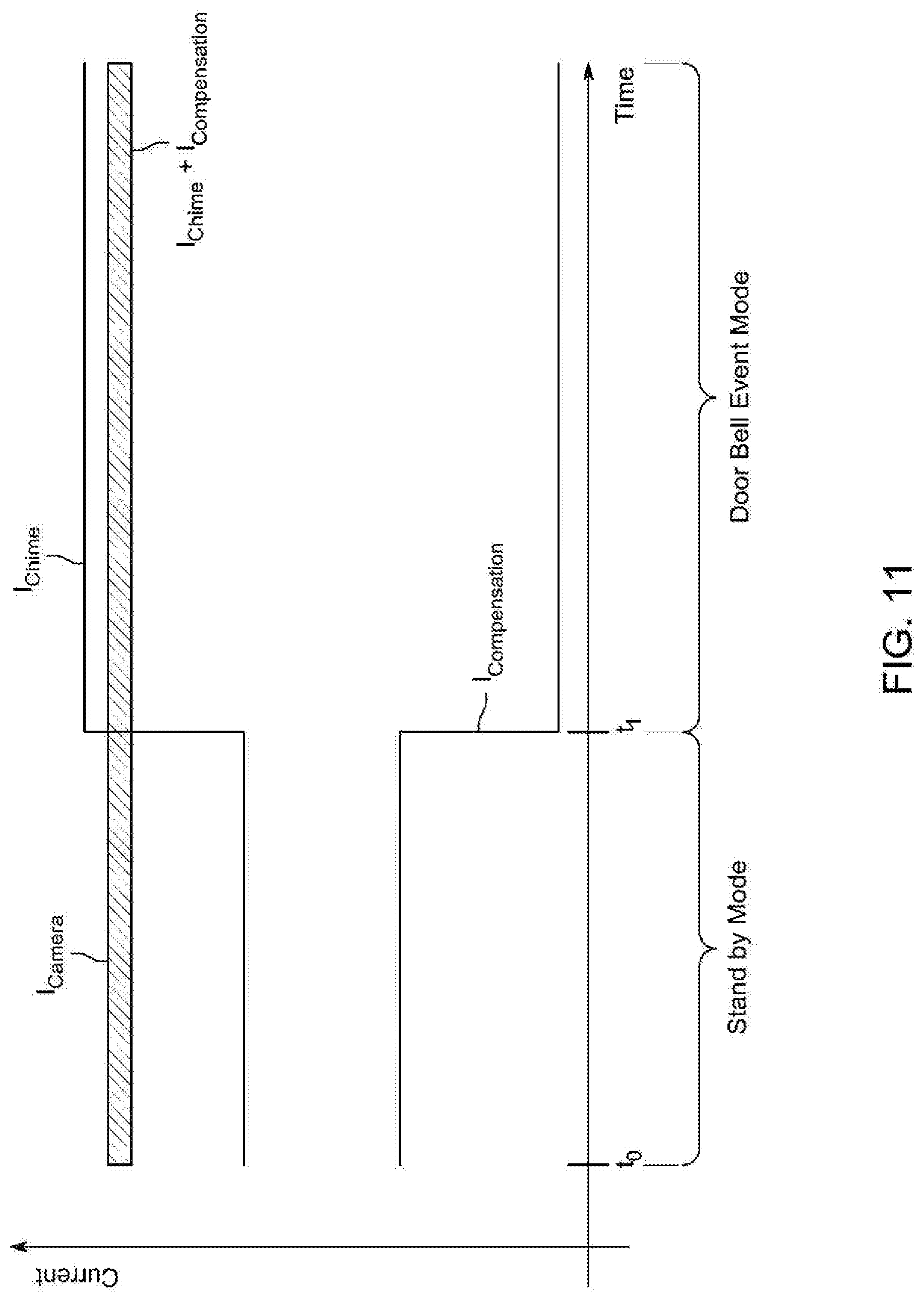
D00014
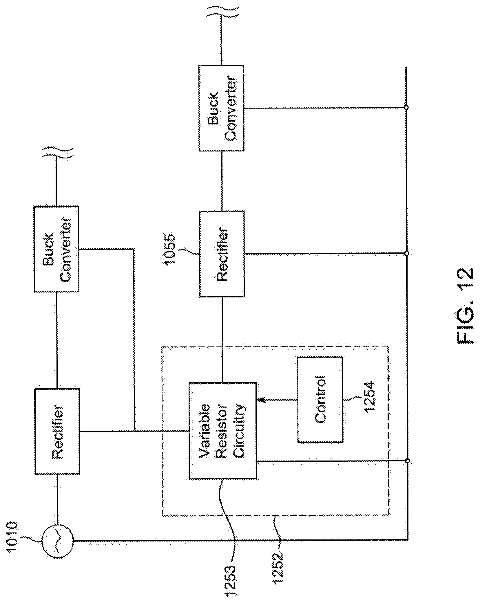
D00015

D00016
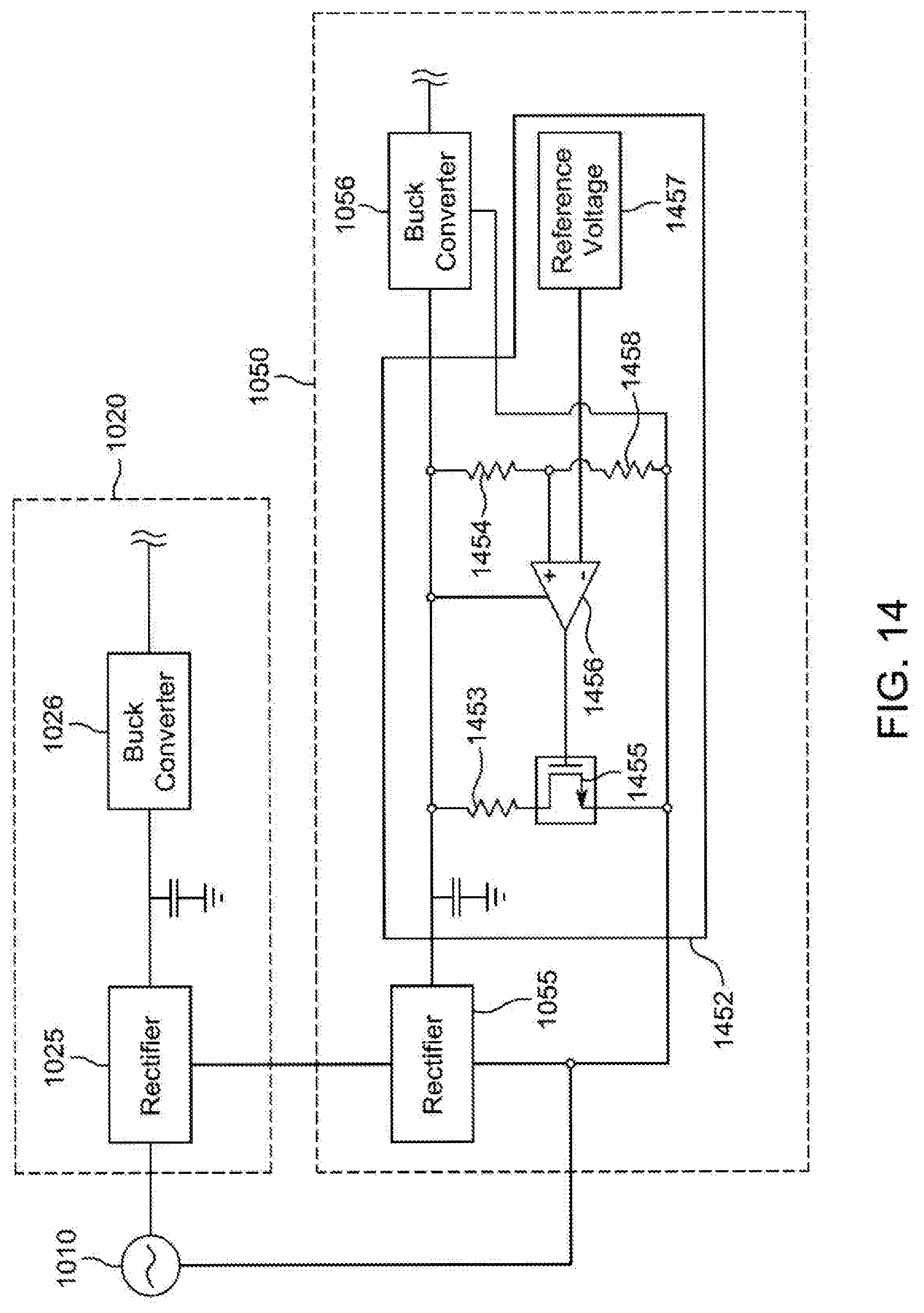
XML
uspto.report is an independent third-party trademark research tool that is not affiliated, endorsed, or sponsored by the United States Patent and Trademark Office (USPTO) or any other governmental organization. The information provided by uspto.report is based on publicly available data at the time of writing and is intended for informational purposes only.
While we strive to provide accurate and up-to-date information, we do not guarantee the accuracy, completeness, reliability, or suitability of the information displayed on this site. The use of this site is at your own risk. Any reliance you place on such information is therefore strictly at your own risk.
All official trademark data, including owner information, should be verified by visiting the official USPTO website at www.uspto.gov. This site is not intended to replace professional legal advice and should not be used as a substitute for consulting with a legal professional who is knowledgeable about trademark law.