Roller Structure And Method Of Manufacturing Same
WANG; TING-JUI
U.S. patent application number 16/531239 was filed with the patent office on 2019-11-21 for roller structure and method of manufacturing same. The applicant listed for this patent is FIVETECH TECHNOLOGY INC.. Invention is credited to TING-JUI WANG.
| Application Number | 20190353202 16/531239 |
| Document ID | / |
| Family ID | 68533545 |
| Filed Date | 2019-11-21 |


| United States Patent Application | 20190353202 |
| Kind Code | A1 |
| WANG; TING-JUI | November 21, 2019 |
ROLLER STRUCTURE AND METHOD OF MANUFACTURING SAME
Abstract
A roller structure includes a roller having an axial hole and an axle portion disposed in the axial hole to allow the roller to rotate about the axle portion; a sleeve with an end disposed at an end of the axle portion and another end having a fitting portion, the fitting portion being fitted to a carried object, the sleeve has a first blocking portion positioned proximate to a side of the roller to allow the roller to rotate between the first blocking portion and the fitting portion, wherein one of the axle portion, the axial hole and the first blocking portion has a substance conducive to reduction of friction between the roller and the sleeve. A method of manufacturing the roller structure is further introduced.
| Inventors: | WANG; TING-JUI; (NEW TAIPEI CITY, TW) | ||||||||||
| Applicant: |
|
||||||||||
|---|---|---|---|---|---|---|---|---|---|---|---|
| Family ID: | 68533545 | ||||||||||
| Appl. No.: | 16/531239 | ||||||||||
| Filed: | August 5, 2019 |
Related U.S. Patent Documents
| Application Number | Filing Date | Patent Number | ||
|---|---|---|---|---|
| 14940222 | Nov 13, 2015 | |||
| 16531239 | ||||
| Current U.S. Class: | 1/1 |
| Current CPC Class: | F16C 2314/72 20130101; F16C 13/006 20130101; B23P 15/003 20130101; F16C 13/022 20130101; A47B 88/437 20170101; F16C 33/6696 20130101; F16C 33/6637 20130101 |
| International Class: | F16C 13/00 20060101 F16C013/00; F16C 33/66 20060101 F16C033/66 |
Foreign Application Data
| Date | Code | Application Number |
|---|---|---|
| Nov 17, 2014 | TW | 103139832 |
Claims
1. A roller structure, comprising a roller having an axial hole and an axle portion disposed in the axial hole to allow the roller to rotate about the axle portion; a sleeve with an end disposed at an end of the axle portion and another end having a fitting portion, the fitting portion being fitted to a carried object, the sleeve has a first blocking portion positioned proximate to a side of the roller to allow the roller to rotate between the first blocking portion and the fitting portion, wherein one of the axle portion, the axial hole and the first blocking portion has a substance conducive to reduction of friction between the roller and the sleeve.
2. The roller structure of claim 1, wherein friction between the roller rolling and the sleeve is less than friction between a roller surface contact object and the roller rolling on the roller surface contact object, allowing the roller to roll on the roller surface contact object and the axle portion under an applied force.
3. The roller structure of claim 1, wherein the substance conducive to reduction of friction is liquid, solid, powder or aerosol.
4. The roller structure of claim 1, wherein the substance conducive to reduction of friction is Teflon, oil, plastic, lubricant, pad or washer.
5. The roller structure of claim 1, wherein friction between the roller and the sleeve is less than friction between a roller surface contact object and the roller rolling on the roller surface contact object while the roller is rolling and bearing the weight of the carried object.
6. The roller structure of claim 1, wherein the substance conducive to reduction of friction is coated or mounted on one of the axle portion, the axial hole and the first blocking portion by spraying, soaking, adhesion, engagement, electroplating, smearing, adsorption or fastening.
7. The roller structure of claim 1, further comprising a second blocking portion disposed at another end of the axle portion and positioned proximate to another side of the roller to allow the roller to rotate between the first blocking portion and the second blocking portion, the second blocking portion having a substance conducive to reduction of friction between the roller and the sleeve.
8. The roller structure of claim 7, wherein the substance conducive to reduction of friction is coated or mounted on the second blocking portion by spraying, soaking, adhesion, engagement, electroplating, smearing, adsorption or fastening.
9. A method of manufacturing the roller structure of claim 1, comprising a step of coating or mounting on one of the axle portion, the axial hole, the first blocking portion and the second blocking portion a substance conducive to reduction of friction between the roller and the sleeve.
Description
CROSS-REFERENCE TO RELATED APPLICATION
[0001] This application is a continuation-in-part patent application of U.S. application Ser. No. 14/940,222 filed on Nov. 13, 2015, the entire contents of which are hereby incorporated by reference for which priority is claimed under 35 U.S.C. .sctn. 120.
BACKGROUND OF THE INVENTION
1. Field of the Invention
[0002] The present disclosure relates to roller structures and methods of manufacturing the same, and in particular to a roller structure conducive to reduction of friction a roller rolling and thereby enhancement of the ease of the rolling of the roller with a view to enhancing ease of use, and a method of manufacturing the roller structure.
2. Description of the Related Art
[0003] It is well known that rollers are mounted on a movable object, such as a sliding door of an apparatus or cabinet, a drawer, or a movable board, to reduce the friction between the movable object and a rail or any other object. Given the rolling contact between each rolling roller and the track or any other object, the friction therebetween decreases so as to render movement smooth.
[0004] However, conventional roller assembly structures and methods of manufacturing the same still have room for improvement. For instance, when rolling, conventional rollers have to bear the weight of a moving object, and thus the friction between the roller surface and an external rolling contact surface, or between the inner rim of the roller and the contact surface of its axle portion, is excessively great to the detriment of the rolling.
[0005] Therefore, it is important to provide a roller structure and a method of manufacturing the same to effectively reduce the rolling friction of the roller, and thus the roller rolls easily, thereby enhancing ease of use.
BRIEF SUMMARY OF THE INVENTION
[0006] In view of the aforesaid drawbacks of the prior art, it is an objective of the present disclosure to provide a roller structure and a method of manufacturing the same to effectively reduce the rolling friction of the roller, and thus the roller rolls easily, thereby enhancing ease of use.
[0007] To achieve at least the above objective, the present disclosure provides a roller structure, comprising a roller having an axial hole and an axle portion disposed in the axial hole to allow the roller to rotate about the axle portion; a sleeve with an end disposed at an end of the axle portion and another end having a fitting portion, the fitting portion being fitted to a carried object, the sleeve has a first blocking portion positioned proximate to a side of the roller to allow the roller to rotate between the first blocking portion and the fitting portion, wherein one of the axle portion, the axial hole and the first blocking portion has a substance conducive to reduction of friction between the roller and the sleeve.
[0008] Regarding the roller structure, friction between the roller rolling and the sleeve is less than friction between a roller surface contact object and the roller rolling on the roller surface contact object, allowing the roller to roll on the roller surface contact object and the axle portion under an applied force.
[0009] Regarding the roller structure, the substance conducive to reduction of friction is liquid, solid, powder or aerosol.
[0010] Regarding the roller structure, the substance conducive to reduction of friction is Teflon, oil, plastic, lubricant, pad or washer.
[0011] Regarding the roller structure, friction between the roller and the sleeve is less than friction between a roller surface contact object and the roller rolling on the roller surface contact object while the roller is rolling and bearing the weight of the carried obj ect.
[0012] Regarding the roller structure, the substance conducive to reduction of friction is coated or mounted on one of the axle portion, the axial hole and the first blocking portion by spraying, soaking, adhesion, engagement, electroplating, smearing, adsorption or fastening.
[0013] The roller structure further comprises a second blocking portion disposed at another end of the axle portion and positioned proximate to another side of the roller to allow the roller to rotate between the first blocking portion and the second blocking portion, the second blocking portion having a substance conducive to reduction of friction between the roller and the sleeve.
[0014] Regarding the roller structure, substance conducive to reduction of friction is coated or mounted on the second blocking portion by spraying, soaking, adhesion, engagement, electroplating, smearing, adsorption or fastening.
[0015] The present disclosure further provides a method of manufacturing a roller structure, wherein a substance conducive to reduction of friction is coated or mounted on the axle portion, the axial hole, the first blocking portion or the second blocking portion to reduce friction between the roller and the sleeve.
[0016] Therefore, the roller structure and the method of manufacturing the same according to the present disclosure effectively reduce the rolling friction of the roller, and thus the roller rolls easily, thereby enhancing ease of use.
BRIEF DESCRIPTION OF THE DRAWINGS
[0017] FIG. 1 is an exploded view of a roller structure according to the first embodiment of the present disclosure.
[0018] FIG. 2 is a schematic view of how the roller structure according to the first embodiment of the present disclosure operates.
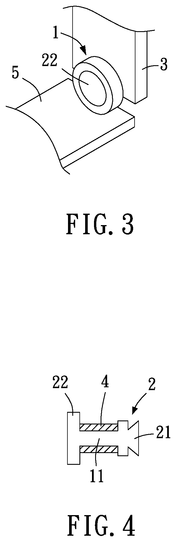
[0019] FIG. 3 is another schematic view of how the roller structure according to the first embodiment of the present disclosure operates.
[0020] FIG. 4 is a schematic view of a substance conducive to reduction of friction according to the second embodiment of the present disclosure.
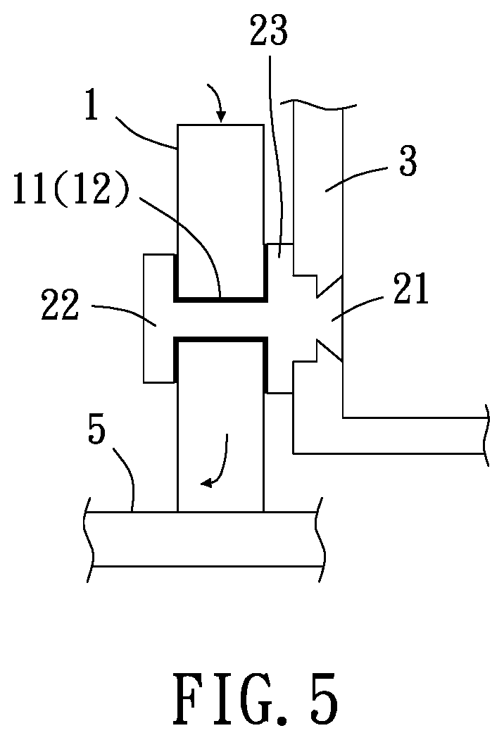
[0021] FIG. 5 is a cross-sectional view of the roller structure according to the third embodiment of the present disclosure.
DETAILED DESCRIPTION OF THE INVETION
[0022] To facilitate understanding of the object, characteristics and effects of this present disclosure, embodiments together with the attached drawings for the detailed description of the present disclosure are provided.
[0023] Referring to FIG. 1 through FIG. 4, the present disclosure provides a roller structure and a method of manufacturing the same. The roller structure comprises a roller 1 and a sleeve 2. The roller 1 has an axle portion 11 which the roller 1 rotates about. The roller 1 has an axial hole 12. The axle portion 11 is disposed in the axial hole 12 such that the roller 1 rotates about the axle portion 11. The sleeve 2 has one end disposed at one end of the axle portion 11. The other end of the sleeve 2 has a fitting portion 21. The fitting portion 21 is fitted to a carried object 3. The sleeve 2 has a first blocking portion 22 positioned proximate to one side of the roller 1 and disposed at the other end of the axle portion 11; hence, the roller 1 rotates between the first blocking portion 22 and the fitting portion 21. A substance 4 conducive to reduction of friction is coated or mounted on the axle portion 11, the axial hole 12 and the first blocking portion 22 to reduce friction between the roller 1 and the sleeve 2, so as to reduce the rolling friction of the roller 1 and allow the roller 1 to rotate easily, thereby enhancing ease of use.
[0024] In a preferred embodiment of the present disclosure, the friction between the roller 1 rolling and the sleeve 2 is less than the friction between a roller surface contact object 5 and the roller 1 rolling on the roller surface contact object 5 to allow the roller 1 to roll on the roller surface contact object 5 and about the axle portion 11 under an applied force. Hence, the roller structure of the present disclosure effectively reduces the rolling friction of the roller 1, and thus the roller 1 rotates easily, thereby enhancing ease of use.
[0025] In a preferred embodiment of the present disclosure, the substance 4 conducive to reduction of friction is liquid, solid, powder or aerosol. Hence, the nature of the substance 4 conducive to reduction of friction is chosen according to whether the substance 4 conducive to reduction of friction is coated or mounted, so as to facilitate the manufacturing of the substance 4 conducive to reduction of friction, thereby rendering the present disclosure practical.
[0026] In a preferred embodiment of the present disclosure, the substance 4 conducive to reduction of friction is Teflon, oil, plastic, lubricant, pad or washer. As shown in FIG. 4, the substance 4 conducive to reduction of friction is a washer made of a material according to whether it is coated or mounted, so as to facilitate the manufacturing of the substance 4 conducive to reduction of friction, thereby rendering the present disclosure practical.
[0027] In a preferred embodiment of the present disclosure, the friction between the roller 1 and the sleeve 2 is less than the friction between a roller surface contact object 5 and the roller 1 rolling on the roller surface contact object 5 while the roller 1 is rolling and bearing the weight of the carried object 3. Therefore, the roller structure of the present disclosure effectively reduces the rolling friction of the roller 1, and thus the roller 1 rotates easily, thereby enhancing ease of use.
[0028] In a preferred embodiment of the present disclosure, the substance 4 conducive to reduction of friction is coated or mounted on the axle portion 11, the axial hole 12 and the first blocking portion 22 by spraying, soaking, adhesion, engagement, electroplating, smearing, adsorption or fastening, depending on whether the substance 4 conducive to reduction of friction is coated or mounted, so as to facilitate the manufacturing of the substance 4 conducive to reduction of friction. Therefore, the present disclosure is practical.
[0029] Referring to FIG. 5, in a preferred embodiment of the present disclosure, the roller structure further comprises a second blocking portion 23 disposed at the other end of the axle portion 11 and positioned proximate to the other side of the roller 1 such that the roller 1 rotates between the first blocking portion 22 and the second blocking portion 23. The substance 4 conducive to reduction of friction is coated or mounted on the second blocking portion 23 to reduce the friction between the roller 1 and the sleeve 2. Hence, the roller structure of the present disclosure effectively reduces the rolling friction of the roller 1, and thus the roller 1 rotates easily, thereby enhancing ease of use.
[0030] In a preferred embodiment of the present disclosure, the substance 4 conducive to reduction of friction is coated or mounted on the second blocking portion 23 by spraying, soaking, adhesion, engagement, electroplating, smearing, adsorption or fastening as need to facilitate the manufacturing of the substance 4 conducive to reduction of friction and thereby render the present disclosure practical.
[0031] The present disclosure further provides a method of manufacturing a roller structure, wherein the substance 4 conducive to reduction of friction is coated or mounted on the axle portion 11, the axial hole 12, the first blocking portion 22 and the second blocking portion 23 to reduce the friction between the roller 1 and the sleeve 2. Therefore, the method of manufacturing a roller structure according to the present disclosure effectively reduces the rolling friction of the roller 1, and thus the roller 1 rotates easily, thereby enhancing ease of use.
[0032] While the present disclosure has been described by means of specific embodiments, numerous modifications and variations could be made thereto by those skilled in the art without departing from the scope and spirit of the present disclosure set forth in the claims.
* * * * *
D00000
D00001
D00002
D00003
XML
uspto.report is an independent third-party trademark research tool that is not affiliated, endorsed, or sponsored by the United States Patent and Trademark Office (USPTO) or any other governmental organization. The information provided by uspto.report is based on publicly available data at the time of writing and is intended for informational purposes only.
While we strive to provide accurate and up-to-date information, we do not guarantee the accuracy, completeness, reliability, or suitability of the information displayed on this site. The use of this site is at your own risk. Any reliance you place on such information is therefore strictly at your own risk.
All official trademark data, including owner information, should be verified by visiting the official USPTO website at www.uspto.gov. This site is not intended to replace professional legal advice and should not be used as a substitute for consulting with a legal professional who is knowledgeable about trademark law.