Expanding And Collapsing Apparatus And Methods Of Use
BROWN; Gareth Edward George
U.S. patent application number 16/066046 was filed with the patent office on 2019-11-21 for expanding and collapsing apparatus and methods of use. The applicant listed for this patent is PEAK WELL SYSTEMS LIMITED, PEAK WELL SYSTEMS PTY LTD. Invention is credited to Gareth Edward George BROWN.
| Application Number | 20190352988 16/066046 |
| Document ID | / |
| Family ID | 57963362 |
| Filed Date | 2019-11-21 |


View All Diagrams
| United States Patent Application | 20190352988 |
| Kind Code | A1 |
| BROWN; Gareth Edward George | November 21, 2019 |
EXPANDING AND COLLAPSING APPARATUS AND METHODS OF USE
Abstract
The invention provides an expanding and collapsing ring apparatus (171) and method of use. The expanding and collapsing ring comprises a plurality of elements (177) assembled together to form a ring structure (172, 173a, 173b) oriented in a plane around a longitudinal axis. The ring structure is operable to be moved between a collapsed condition and a first expanded condition by movement of the plurality of elements on actuation by an axial force. The apparatus further comprises a secondary expanding and collapsing mechanism operable to move the ring structure between its collapsed condition or its first expanded conditions to a second expanded condition on actuation by an axial force. Applications of the invention include oilfield devices, including anti-extrusion rings, plugs, packers, locks, patching tools, connection systems, and variable diameter tools run in a wellbore.
| Inventors: | BROWN; Gareth Edward George; (Ellon, GB) | ||||||||||
| Applicant: |
|
||||||||||
|---|---|---|---|---|---|---|---|---|---|---|---|
| Family ID: | 57963362 | ||||||||||
| Appl. No.: | 16/066046 | ||||||||||
| Filed: | December 23, 2016 | ||||||||||
| PCT Filed: | December 23, 2016 | ||||||||||
| PCT NO: | PCT/GB2016/054065 | ||||||||||
| 371 Date: | June 25, 2018 |
| Current U.S. Class: | 1/1 |
| Current CPC Class: | E21B 47/08 20130101; E21B 23/01 20130101; E21B 33/134 20130101; E21B 33/1216 20130101; E21B 10/32 20130101; E21B 17/1014 20130101; E21B 33/04 20130101; E21B 33/128 20130101 |
| International Class: | E21B 23/01 20060101 E21B023/01; E21B 33/128 20060101 E21B033/128 |
Foreign Application Data
| Date | Code | Application Number |
|---|---|---|
| Dec 23, 2015 | GB | 1522725.9 |
| Dec 23, 2015 | GB | 1522741.6 |
Claims
1. An expanding and collapsing ring apparatus comprising: a plurality of elements assembled together to form a ring structure oriented in a plane around a longitudinal axis; wherein the ring structure is operable to be moved between a collapsed condition and a first expanded condition by movement of the plurality of elements on actuation by an axial force; and wherein the apparatus further comprises a secondary expanding and collapsing mechanism operable to move the ring structure between its collapsed condition or its first expanded condition to a second expanded condition on actuation by an axial force.
2. The apparatus according to claim 1, wherein the plurality of elements is operable to be moved relative to one another between the expanded and collapsed conditions by sliding the elements with respect to one another in the plane of the ring structure.
3. The apparatus according to claim 1, wherein the ring structure comprises one or more ring surfaces configured to be presented to an auxiliary surface when actuated to an expanded condition or a collapsed condition.
4. The apparatus according to claim 3, wherein the one or more ring surfaces comprises a substantially cylindrical surface arranged to contact or otherwise interact with an inner surface of a tubular or bore.
5. The apparatus according to claim 3, wherein the ring surface is substantially smooth.
6. The apparatus according to claim 3, wherein the ring surface is provided with one or more functional formations thereon, for interacting with an auxiliary surface.
7. The apparatus according to claim 1, wherein the elements are configured to move between their expanded and collapsed radial positions in a path which is tangential to a circle described around and concentric with the longitudinal axis.
8. The apparatus according to claim 1, wherein each element of the ring structure comprises a first contact surface and second contact surface respectively in abutment with first and second adjacent elements, and wherein the elements are configured to slide relative to one another along their respective contact surfaces.
9. The apparatus according to claim 8, wherein the first contact surface and/or the second contact surface are oriented tangentially to a circle described around and concentric with the longitudinal axis.
10. The apparatus according to claim 8, wherein the first contact surface and the second contact surface converge towards one another in a direction towards an inner surface of the ring structure.
11. (canceled)
12. The apparatus according to claim 1, wherein the elements are provided with interlocking profiles for interlocking with an adjacent element.
13. The apparatus according to claim 1, comprising a biasing means configured to bias the ring structure to one of its expanded or collapsed conditions.
14-15. (canceled)
16. The apparatus according to claim 1, wherein the ring structure is a first ring structure, and the secondary expanding and collapsing mechanism comprises a second ring structure, wherein the second ring structure is operable to move the first ring structure from an intermediate expanded condition to a fully expanded condition.
17. The apparatus according to claim 16, wherein the second ring structure is one of a second pair of ring structures, operable to move the first ring structure from an intermediate expanded condition to a fully expanded condition.
18. The apparatus according to claim 17, wherein each of the second pair of ring structures are disposed on opposing sides of the first ring structure.
19. The apparatus according to claim 17, wherein each of the second pair of ring structures comprises a plurality of second elements assembled together to form the second ring structure oriented in a plane around the longitudinal axis.
20. The apparatus according to claim 19, wherein the plurality of second elements is operable to be moved relative to one another between expanded and collapsed conditions of the respective second ring structures by sliding the second elements with respect to one another in the planes of the second ring structures.
21. The apparatus according to claim 16, wherein each of the second ring structures defines a respective outer surface, which is inclined with respect to a surface parallel to the longitudinal axis.
22. The apparatus according to claim 21, wherein the respective outer surfaces are conical wedge surfaces which face the first ring structure.
23. The apparatus according to claim 19, wherein the plurality of elements of the second ring structures are operable to be moved between their expanded and collapsed conditions by sliding with respect to one another in the plane of the second ring structure, in a direction tangential to a circle concentric with the second ring structure.
24. The apparatus according to claim 1, wherein the apparatus comprises a plurality of additional ring structures arranged in functional pairs, and operable to move the first ring structure from an intermediate expanded condition to a subsequent intermediate expanded condition, or a fully expanded condition.
25. The apparatus according to claim 24, wherein each additional ring structure comprises a biasing means configured to bias the first ring structure to one of its expanded or collapsed conditions, and wherein biasing means of the first and second or additional ring structures are selected to define a sequence of expanding and collapsing of the apparatus.
26-29. (canceled)
30. The apparatus according claim 1, wherein each of a functional pair of additional ring structures and/or the elements thereof are configured to limit the travel of a corresponding additional ring structures and/or the elements thereof.
31. An oilfield tool comprising the apparatus of claim 1.
32. The oilfield tool according to claim 31, configured as a downhole tool selected from the group consisting of: a plug, a packer, an anchor, a tubing hanger, or a downhole locking tool.
33-34. (canceled)
35. A variable diameter downhole tool comprising an apparatus according to claim 1.
36. (canceled)
37. A connector system comprising a first connector and a second connector, wherein one of the first and second connectors comprises the apparatus of claim 1.
38. A patch apparatus for a fluid conduit or tubular, the patch apparatus comprising the apparatus of claim 1.
39. A method of expanding an apparatus, the method comprising: providing an apparatus comprising: a plurality of elements assembled together to form a ring structure oriented in a plane around a longitudinal axis; and a secondary expanding and collapsing mechanism; imparting an axial force to the ring structure to move the plurality of elements from a collapsed condition to a first expanded condition; and imparting an axial force to the secondary expanding and collapsing mechanism to move the first ring structure from its first expanded condition to a second expanded condition.
40. A method of collapsing an apparatus, the method comprising: providing an apparatus comprising: a plurality of elements assembled together to form a ring structure oriented in a plane around a longitudinal axis; and a secondary expanding and collapsing mechanism; releasing or reducing an axial force from the secondary expanding and collapsing mechanism to move the ring structure from a second expanded condition to a first expanded condition; and releasing or reducing an axial force from the ring structure to move the plurality of elements, thereby moving the ring structure from the first expanded condition to a collapsed condition.
Description
[0001] The present invention relates to an expanding and collapsing apparatus and methods of use, and in particular aspects, to an expanding apparatus in the form of a ring, operable to move between a collapsed condition and an expanded condition. The invention also relates to tools and devices incorporating the expansion apparatus and methods of use. Preferred embodiments of the invention relate to oilfield apparatus (including but not limited to downhole apparatus and wellhead apparatus) incorporating the apparatus and methods of use.
BACKGROUND TO THE INVENTION
[0002] In many fields of mechanical engineering, and in the field of hydrocarbon exploration and production in particular, it is known to provide expansion mechanisms for the physical interaction of tubular components. Expansion mechanisms may expand outwardly to engage an external surface, or may collapse inwardly to engage an internal surface.
[0003] Applications are many and varied, but those in hydrocarbon exploration and production include the actuation and setting of flow barriers and seal elements such as plugs and packers, anchoring and positioning tools such as wellbore anchors, casing and liner hangers, and locking mechanisms for setting equipment downhole. Other applications include providing mechanical support or back up for elements such as elastomers or inflatable bladders.
[0004] A typical anti-extrusion ring is positioned between a packer or seal element and its actuating slip members, and is formed from a split or segmented metallic ring. During deployment of the packer or seal element, the segments move to a radially expanded condition. During expansion and at the radially expanded condition, spaces are formed between the segments, as they are required to occupy a larger annular volume. These spaces create extrusion gaps, which may result in failure of the packer or seal under working conditions.
[0005] Various configurations have been proposed to minimise the effect of spaces between anti-extrusion segments, including providing multi-layered rings, such that extrusion gaps are blocked by an offset arrangement of segments. For example, U.S. Pat. No. 6,598,672 describes an anti-extrusion rings for a packer assembly which has first and second ring portions which are circumferentially offset to create gaps in circumferentially offset locations.
[0006] U.S. Pat. No. 2,701,615 discloses a well packer comprising an arrangement of crowned spring metal elements which are expanded by relative movement.
[0007] Other proposals, for example those disclosed in U.S. Pat. Nos. 3,572,627, 7,921,921, US 2013/0319654, U.S. Pat. Nos. 7,290,603 and 8,167,033 include arrangements of circumferentially lapped segments. U.S. Pat. No. 3,915,424 describes a similar arrangement in a drilling BOP configuration, in which overlapping anti-extrusion members are actuated by a radial force to move radially and circumferentially to a collapsed position which supports annular sealing elements. Such arrangements avoid introducing extrusion gaps during expansion, but create a ring with uneven or stepped faces or flanks. These configurations do not provide an unbroken support wall for a sealing element, are spatially inefficient, and may be difficult to reliably move back to their collapsed configurations.
[0008] U.S. Pat. No. 8,083,001 proposes an alternative configuration in which two sets of wedge shaped segments are brought together by sliding axially with respect to one another to create an expanded gauge ring.
[0009] In anchoring, positioning, setting, locking and connection applications, radially expanding and collapsing structures are typically circumferentially distributed at discrete locations when at their increased outer diameter. This reduces the surface area available to contact an auxiliary engagement surface, and therefore limits the maximum force and pressure rating for a given size of device.
SUMMARY OF THE INVENTION
[0010] It is amongst the claims and objects of the invention to provide an expanding and collapsing apparatus and methods of use which obviate or mitigate disadvantages of previously proposed expanding and collapsing apparatus.
[0011] It is amongst the aims and objects of the invention to provide an oilfield apparatus, including a downhole apparatus or a wellhead apparatus, incorporating an expanding and collapsing apparatus, which obviates or mitigates disadvantages of prior art oilfield apparatus.
[0012] Further aims and objects of the invention will be apparent from reading the following description.
[0013] According to a first aspect of the invention, there is provided an expanding and collapsing ring apparatus comprising:
a plurality of elements assembled together to form a ring structure oriented in a plane around a longitudinal axis; wherein the ring structure is operable to be moved between a collapsed condition and a first expanded condition by movement of the plurality of elements on actuation by an axial force; and wherein the apparatus further comprises a secondary expanding and collapsing mechanism operable to move the first ring structure between its collapsed condition or its first expanded condition to a second expanded condition on actuation by an axial force.
[0014] The ring structure may be a first ring structure, and the apparatus may comprise at least one additional ring structure, wherein the additional ring structure is operable to move the first ring structure from an intermediate expanded condition to a fully expanded condition.
[0015] Preferably, the plurality of elements is operable to be moved relative to one another between the expanded and collapsed conditions, and more preferably, is operable to be moved by sliding the elements with respect to one another in the plane of the ring structure.
[0016] The plane of the ring structure may be perpendicular to the longitudinal axis. The ring structure, and its plane of orientation, may be operable to move on the apparatus during expansion and/or collapsing. The movement of the plane may be an axial sliding movement, during expanding and/or collapsing of the ring structure.
[0017] The apparatus may be normally collapsed, and may be actuated to be expanded. Alternatively, the apparatus may be normally expanded, and may be actuated to be collapsed.
[0018] The ring structure may comprise one or more ring surfaces, which may be presented to an auxiliary surface, for example the surface of a tubular, when actuated to an expanded condition or a collapsed condition. The one or more ring surfaces may include a ring surface which is parallel to the longitudinal axis of the apparatus. Alternatively, or in addition, the one or more ring surfaces may include a surface which is perpendicular to the longitudinal axis of the apparatus, and/or a surface which is inclined to the longitudinal axis of the apparatus.
[0019] The ring surface may be an outer ring surface, and may be a substantially cylindrical surface. The ring surface may be arranged to contact or otherwise interact with an inner surface of a tubular or bore.
[0020] The ring surface may be substantially smooth. Alternatively, the ring surface may be profiled, and/or may provided with one or more functional formations thereon, for interacting with an auxiliary surface.
[0021] In the collapsed condition, the elements may be arranged generally at collapsed radial positions, and may define a collapsed outer diameter and inner diameter of the ring structure.
[0022] In the first expanded condition, the elements may be arranged generally at expanded radial positions, and may define a first expanded outer diameter and inner diameter of the ring structure. The ring surface may be located at or on the expanded outer diameter of the ring structure, or may be located at or on the collapsed inner diameter of the ring structure.
[0023] The elements may be configured to move between their first expanded and collapsed radial positions in a path which is tangential to a circle described around and concentric with the longitudinal axis.
[0024] Preferably, each element of the ring structure comprises a first contact surface and second contact surface respectively in abutment with first and second adjacent elements. The elements may be configured to slide relative to one another along their respective contact surfaces.
[0025] The first contact surface and/or the second contact surface may be oriented tangentially to a circle described around and concentric with the longitudinal axis. The first contact surface and the second contact surface are preferably non-parallel. The first contact surface and the second contact surface may converge towards one another in a direction towards an inner surface of the ring structure (and may therefore diverge away from one another in a direction away from an inner surface of the ring structure).
[0026] At least some of the elements are preferably provided with interlocking profiles for interlocking with an adjacent element. Preferably the interlocking profiles are formed in the first and/or second contact surfaces. Preferably, an element is configured to interlock with a contact surface of an adjacent element. Such interlocking may prevent or restrict separation of assembled adjacent elements in a circumferential and/or radial direction of the ring structure, while enabling relative sliding movement of adjacent elements.
[0027] Preferably, at least some of, and more preferably all of, the elements assembled to form a ring are identical to one another, and each comprises an interlocking profile which is configured to interlock with a corresponding interlocking profile on another element. The interlocking profiles may comprise at least one recess such as groove, and at least one protrusion, such as a tongue or a pin, configured to be received in the groove. The interlocking profiles may comprise at least one dovetail recess and dovetail protrusion.
[0028] The first and second contact surfaces of an element may be oriented on first and second planes, which may intersect an inner surface of the ring at first and second intersection lines, such that a sector of an imaginary cylinder is defined between the longitudinal axis and the intersection lines. The central angle of the sector may be 45 degrees or less. Such a configuration corresponds to eight or more elements assembled together to form the ring structure.
[0029] Preferably, the central angle of the sector is 30 degrees or less, corresponding to twelve or more elements assembled together to form the ring. More preferably, the central angle of the sector is in the range of 10 degrees to 20 degrees, corresponding to eighteen to thirty-six elements assembled together to form the ring. In a particular preferred embodiment, the central angle of the sector is 15 degrees, corresponding to twenty-four elements assembled together to form the ring structure.
[0030] Preferably, an angle described between the first contact and second contact surfaces corresponds to the central angle of the sector. Preferably therefore, an angle described between the first contact and second contact surfaces is in the range of 10 degrees to 20 degrees, and in a particular preferred embodiment, the angle described between the first contact and second contact surfaces is 15 degrees, corresponding to twenty-four elements assembled together to form the ring structure.
[0031] In a preferred embodiment, the apparatus comprises a support surface for the ring structure. The support surface may be the outer surface of a mandrel or tubular. The support surface may support the ring structure in a collapsed condition of the apparatus.
[0032] In some embodiments, the apparatus is operated in its second expanded condition, and in other embodiments, the apparatus is operated in its collapsed condition. Preferably, elements forming the ring structure are mutually supportive in an operating condition of the apparatus. Where the operating condition of the apparatus its expanded condition (i.e. when the apparatus is operated in its expanded condition), the ring structure is preferably a substantially solid ring structure in its second expanded condition, and the elements may be fully mutually supported.
[0033] The apparatus may comprise a formation configured to impart a radial expanding or collapsing force component to the elements of a ring structure and/or secondary expanding and collapsing mechanism from an axial actuation force. The apparatus may comprise a pair of formations configured to impart a radial expanding or collapsing force component to the elements of a ring structure from an axial actuation force. The formation (or formations) may comprise a wedge or wedge profile, and may comprise a cone wedge or wedge profile.
[0034] The apparatus may comprise a biasing means, which may be configured to bias the first ring structure to one of its expanded or collapsed conditions. The biasing means may comprise a circumferential spring, a garter spring, or a spiral retaining ring. The biasing means may be arranged around an outer surface of a ring structure, to bias it towards a collapsed condition, or may be arranged around an inner surface of a ring structure, to bias it towards an expanded condition. One or more elements may comprise a formation such as a groove for receiving the biasing means. Preferably, grooves in the elements combine to form a circumferential groove in the ring structure. Multiple biasing means may be provided on the ring structure.
[0035] Preferably, the secondary expanding and collapsing mechanism comprises a second ring structure, and more preferably comprises a pair of second ring structures. The second ring structure(s) may be operable to move the first ring structure from an intermediate expanded condition to a fully expanded condition. The pair of second ring structures may be disposed on opposing sides of the first ring structure. The second ring structure(s) may comprise a plurality of second elements assembled together to form the second ring structure oriented in a plane around the longitudinal axis.
[0036] The plurality of second elements may be operable to be moved relative to one another between an expanded and collapsed conditions of the respective second ring structure, and more preferably, is operable to be moved by sliding the second elements with respect to one another in the plane of the second ring structure.
[0037] The second ring structures may define an outer surface, which may be inclined with respect to a surface parallel to the longitudinal axis. The outer surfaces may be conical wedge surfaces, which may face the first ring structure.
[0038] The apparatus may comprise at least one pair of additional ring structures, wherein the pair of additional ring structures are operable to move the first ring structure from an intermediate expanded condition to a fully expanded condition. The pair of additional ring structures may be disposed (axially) on either side of the first ring structure, and may act together to move the ring structure from an intermediate expanded condition to a fully expanded condition.
[0039] The plurality of elements of the additional ring structure may be operable to be moved between the expanded and collapsed conditions by sliding with respect to one another in the plane of the additional ring structure, in a direction tangential to a circle concentric with the additional ring structure. In other respects, the additional ring structure and its elements may have features in common with the ring structure described herein.
[0040] The additional ring structure, and/or its elements, may be operable to transfer an axial actuation force to the elements of the first ring structure. The additional ring structure, and/or its elements may comprise one or more wedge profiles, which may be conical wedge profiles. The one or more wedge profiles may be defined by an outer surface of the elements of the additional ring structure.
[0041] The apparatus may comprise a plurality of additional ring structures, which may be arranged in functional pairs, and/or which may be operable to move the first ring structure from an intermediate expanded condition to a subsequent intermediate expanded condition, or a fully expanded condition.
[0042] Preferably, each additional ring structure comprises a biasing means, which may be configured to bias the first ring structure to one of its expanded or collapsed conditions.
[0043] The biasing means may comprise a circumferential spring, a garter spring, or a spiral retaining ring. Preferably, the biasing means of the first and additional ring structures are selected to define a sequence of expanding and collapsing of the apparatus. Preferably, the biasing means of the first and additional ring structures are selected to expand the centremost ring structure before an adjacent pair of additional ring structures. The biasing means additional ring structures may be selected to expand a first pair of additional ring structures before an adjacent pair of additional ring structures located axially outside of the first pair or additional ring structures.
[0044] The biasing means may be disposed on an outer surface of a ring structure, or may be disposed in a groove on the outer surface of a ring structure.
[0045] Alternatively, or in addition, a biasing means may be disposed in apertures in the elements. The biasing means may be threaded through each element, and may then be joined to make a continuous loop upon assembly. The biasing means may be disposed in-board of the external surface of the elements. The biasing means may be located directly over an interlocking feature such as a dovetail, and/or may be located centrally on the ring structure.
[0046] Preferably, a functional pair of additional ring structures and/or the elements thereof is symmetrical about a centre ring structure. Each of a functional pair of additional ring structures and/or the elements thereof may be configured to move axially with respect to one another on the apparatus, and may be configured to move into abutment with one another. Preferably, each of a functional pair of additional ring structures and/or the elements thereof are configured to limit the travel of a corresponding additional ring structures and/or the elements thereof.
[0047] External profiles of the elements may comprise chamfers, which may at least partially define a surface of one or more flanks of an assembled ring structure.
[0048] An assembled ring structure may comprise at least one flank having an at least partially smoothed conical surface. In use, the at least partially smoothed conical surface may facilitate deployment of the apparatus, for example by improving the sliding action of an adjacent ring on the flank during expansion. The flank may be a flank of a supporting ring structure. The at least one flank may be an inward facing flank, or a flank facing a central ring structure or a ring structure disposed between the flank and a central ring structure.
[0049] Alternatively, or in addition, the elements may be profiled such that the ring structures define at least partially smooth conical surfaces on their outward facing flanks when in their expanded condition. The at least partially smooth conical surfaces may combine in the assembled, expanded apparatus, to provide a substantially or fully smooth surface of flank of the expanded apparatus, which may be suitable for abutment with and/or support of an adjacent element such as an elastomer.
[0050] The surfaces of the plurality of elements may be configured to be presented directly against a surface with which it interacts, such as a borehole wall. Alternatively, or in addition, the apparatus may comprise an intermediate structure or material disposed between the surfaces of the elements and a surface with which it interacts.
[0051] In one embodiment, the elements of the ring structure are configured to conform, deform or compress in a collapsed condition to form a fluid barrier or seal with an object in the throughbore. The elements may be formed, at least partially, from a compressible and/or resilient material, such as an elastomer, rubber or polymer.
[0052] Alternatively, or in addition, the elements may be formed, at least partially, from a metal or metal alloy, and may be coated or covered with a compressible and/or resilient material, such as an elastomer, rubber or polymer.
[0053] According to a second aspect of the invention, there is provided an expanding and collapsing ring apparatus comprising:
a plurality of elements assembled together to form a first ring structure oriented in a plane around a longitudinal axis; wherein the first ring structure is operable to be moved between a collapsed condition and a first expanded condition by movement of the plurality of elements on actuation by an axial force; and wherein the apparatus further comprises at least one pair of additional ring structures, wherein the pair of additional ring structures are operable to move the first ring structure from an intermediate expanded condition to a fully expanded condition.
[0054] The additional ring structure may comprise a plurality of elements assembled together to form a ring structure, and may be oriented in a plane around a longitudinal axis. The additional ring structure may be operable to be moved between an expanded condition and a collapsed condition by movement of the plurality of elements on actuation by an axial force. The plurality of elements of the additional ring structure may be operable to be moved between the expanded and collapsed conditions by sliding with respect to one another in the plane of the additional ring structure, in a direction tangential to a circle concentric with the additional ring structure. In other respects, the additional ring structure and its elements may have features in common with the ring structure described herein.
[0055] Embodiments of the second aspect of the invention may include one or more features of the first aspect of the invention or its embodiments, or vice versa.
[0056] According to a third aspect of the invention, there is provided an oilfield tool comprising the apparatus of any of the first or second aspects of the invention.
[0057] The oilfield tool may be a downhole tool. Alternatively, the oilfield tool may comprise a wellhead tool.
[0058] The downhole tool may comprise a downhole tool selected from the group consisting of a plug, a packer, an anchor, a tubing hanger, or a downhole locking tool.
[0059] The plug may be a bridge plug, and may be a retrievable bridge plug. Alternatively, the plug may be a permanent plug.
[0060] Embodiments of the third aspect of the invention may include one or more features of the first or second aspects of the invention or their embodiments, or vice versa.
[0061] According to a fourth aspect of the invention, there is provided variable diameter downhole tool, the tool comprising an apparatus according to a previous aspect of the invention.
[0062] The downhole tool may be selected from the group consisting of a wellbore centraliser, a wellbore broach tool, and a wellbore drift tool.
[0063] Embodiments of the fourth aspect of the invention may include one or more features of the first or second aspects of the invention or their embodiments, or vice versa.
[0064] According to a fifth of the invention, there is provided a connector system comprising a first connector and a second connector, wherein one of the first and second connectors comprises the apparatus of any of the first or second aspects of the invention.
[0065] Embodiments of the fifth aspect of the invention may include one or more features of the first or second aspects of the invention or their embodiments, or vice versa.
[0066] According to a sixth aspect of the invention, there is provided patch apparatus for a fluid conduit or tubular, the patch apparatus comprising the apparatus of any of the first or second aspects of the invention.
[0067] Embodiments of the sixth aspect of the invention may include one or more features of the first or second aspects of the invention or their embodiments, or vice versa.
[0068] According to a seventh aspect of the invention, there is provided a method of expanding an apparatus, the method comprising:
providing an apparatus comprising: a plurality of elements assembled together to form a ring structure oriented in a plane around a longitudinal axis; and a secondary expanding and collapsing mechanism; imparting an axial force to the ring structure to move the plurality of elements from a collapsed condition to a first expanded condition; and imparting an axial force to the secondary expanding and collapsing mechanism to move the first ring structure from its first expanded condition to a second expanded condition.
[0069] Embodiments of the seventh aspect of the invention may include one or more features of the first or second aspects of the invention or their embodiments, or vice versa.
[0070] According to an eighth aspect of the invention, there is provided a method of collapsing an apparatus, the method comprising:
providing an apparatus comprising: a plurality of elements assembled together to form a ring structure oriented in a plane around a longitudinal axis; and a secondary expanding and collapsing mechanism; imparting an axial force to the ring structure to move the plurality of elements from a collapsed condition to a first expanded condition; and releasing or reducing an axial force from the secondary expanding and collapsing mechanism to move the first ring structure from a second expanded condition to a first expanded condition; and releasing or reducing an axial force from the ring structure to move the plurality of elements, thereby moving the ring structure from the first expanded condition to a collapsed condition.
[0071] Embodiments of the eighth aspect of the invention may include one or more features of the first or second aspects of the invention or their embodiments, or vice versa.
[0072] According to a further aspect of the invention, there is provided an expanding and collapsing ring apparatus comprising:
a plurality of elements assembled together to form a ring structure oriented in a plane around a longitudinal axis; wherein the ring structure is operable to be moved between a collapsed condition and a first expanded condition by movement of the plurality of elements; and wherein the apparatus further comprises a secondary expanding and collapsing mechanism operable to move the first ring structure between its collapsed condition or its first expanded condition to a second expanded condition.
[0073] According to a further aspect of the invention, there is provided an expanding and collapsing ring apparatus comprising:
a plurality of elements assembled together to form a first ring structure oriented in a plane around a longitudinal axis; wherein the first ring structure is operable to be moved between a collapsed condition and a first expanded condition by movement of the plurality of elements; and wherein the apparatus further comprises at least one pair of additional ring structures, wherein the pair of additional ring structures are operable to move the first ring structure from an intermediate expanded condition to a fully expanded condition.
[0074] According to a further aspect of the invention, there is provided a method of expanding an apparatus, the method comprising:
providing an apparatus comprising: a plurality of elements assembled together to form a ring structure oriented in a plane around a longitudinal axis; and a secondary expanding and collapsing mechanism; imparting a force to the ring structure to move the plurality of elements from a collapsed condition to a first expanded condition; and imparting a force to the secondary expanding and collapsing mechanism to move the first ring structure from its first expanded condition to a second expanded condition.
[0075] According to a further aspect of the invention, there is provided a method of collapsing an apparatus, the method comprising:
providing an apparatus comprising: a plurality of elements assembled together to form a ring structure oriented in a plane around a longitudinal axis; and a secondary expanding and collapsing mechanism; imparting a force to the ring structure to move the plurality of elements from a collapsed condition to a first expanded condition; and releasing or reducing a force from the secondary expanding and collapsing mechanism to move the first ring structure from a second expanded condition to a first expanded condition; and releasing or reducing a force from the ring structure to move the plurality of elements, thereby moving the ring structure from the first expanded condition to a collapsed condition.
[0076] According to a further aspect of the invention, there is provided fluid conduit tool comprising the apparatus according to any previous aspect of the invention. The fluid conduit tool may be configured for use in pipelines or other fluid conduits, which may be surface fluid conduits or subsea fluid conduits, and may be oilfield or non-oilfield fluid conduits.
[0077] Embodiments of the further aspects of the invention may include one or more features of the first or second aspects of the invention or their embodiments, or vice versa.
BRIEF DESCRIPTION OF THE DRAWINGS
[0078] There will now be described, by way of example only, various embodiments of the invention with reference to the drawings, of which:
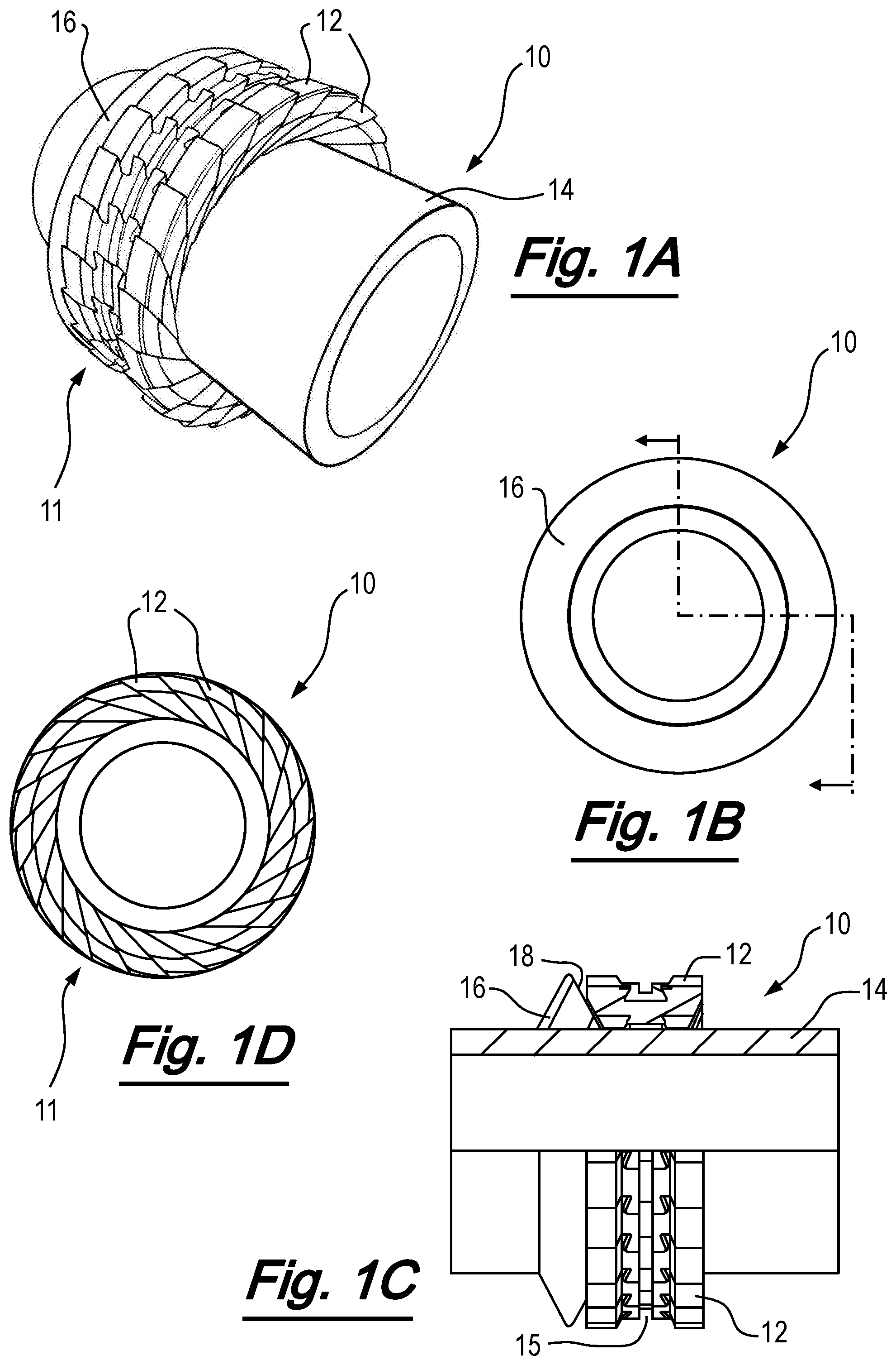
[0079] FIG. 1A to FIG. 1D are respectively perspective, first end, part sectional and second end views of an apparatus useful for understanding the invention, shown in a collapsed condition;
[0080] FIGS. 2A to 2D are respectively perspective, first side, part sectional and second side views of the apparatus of FIGS. 1A to 1D, shown in an expanded condition;
[0081] FIGS. 3A and 3B are geometric representations of an element of the apparatus of FIGS. 1A and 1D, shown from one side;
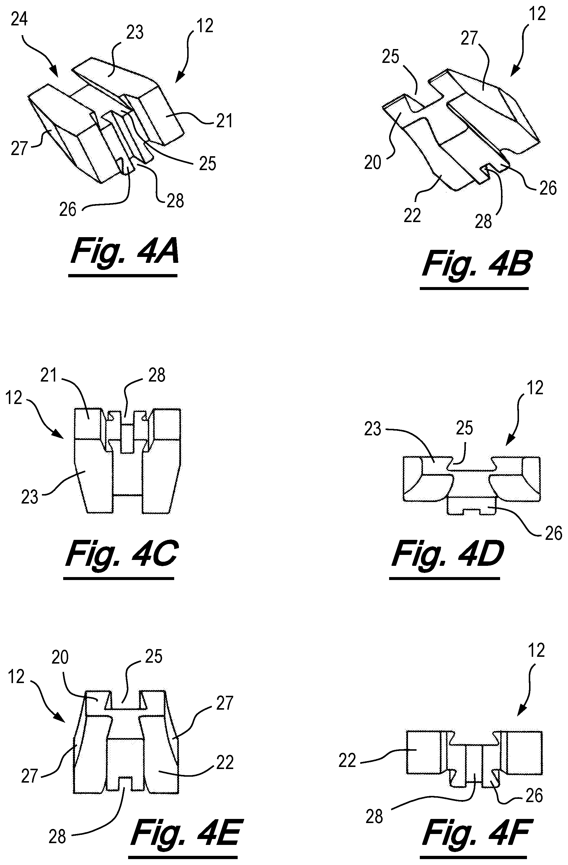
[0082] FIG. 4A to FIG. 4F are respectively first perspective, second perspective, plan, first end, lower, and second end views of an element of the apparatus of FIGS. 1A to 1D;
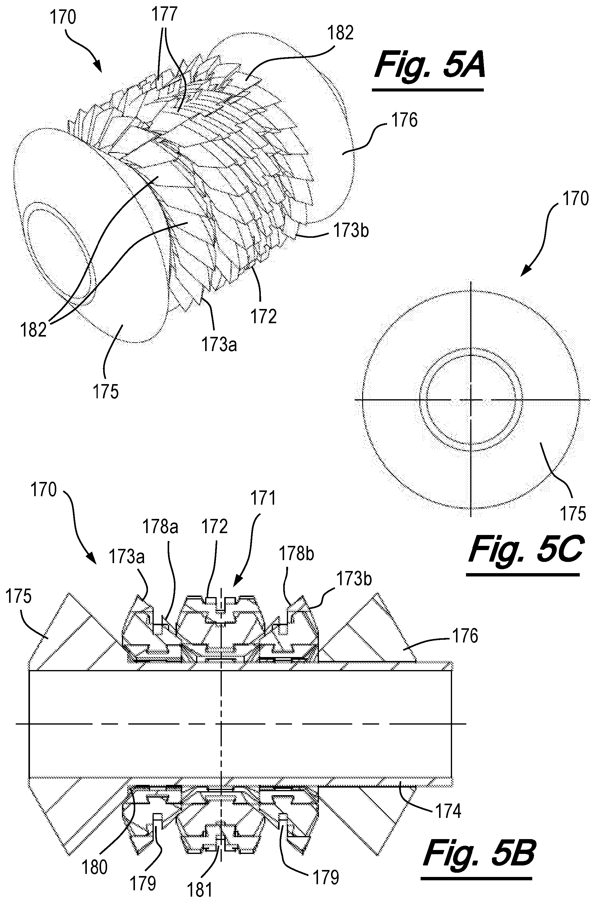
[0083] FIGS. 5A to 5C are respectively perspective, sectional and end views of an apparatus according to an embodiment of the invention, shown in a collapsed condition;
[0084] FIGS. 6A to 6C are respectively perspective, sectional and end views of the apparatus of FIGS. 5A to 5C, shown in an expanded condition;
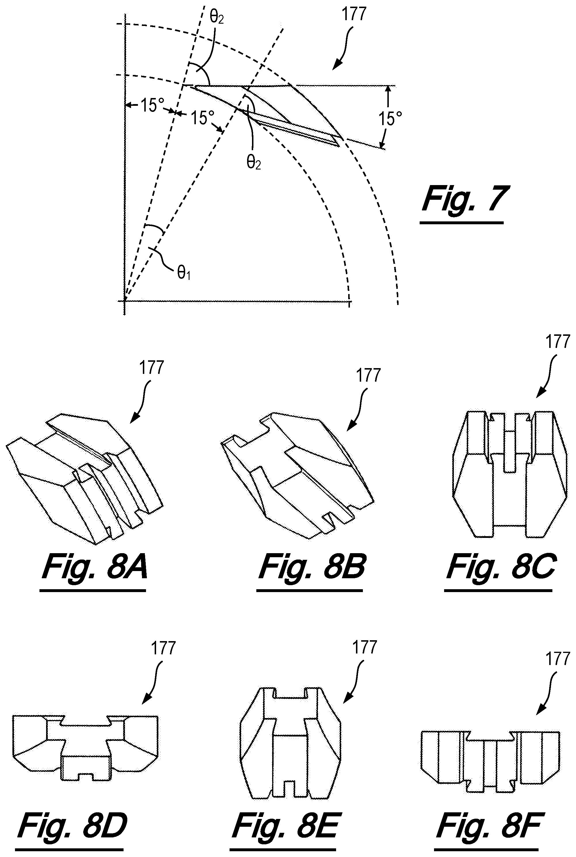
[0085] FIG. 7 is a geometric representation of a centre element of the apparatus of FIGS. 5A to 5C, shown from one side;
[0086] FIGS. 8A to 8F are respectively first perspective, second perspective, plan, first end, lower, and second end views of a centre element of the apparatus of FIGS. 5A to 5C;
[0087] FIG. 9 is a geometric representation of an outer element of the apparatus of FIGS. 5A to 5C, shown from one side;
[0088] FIG. 10A to 10H are respectively first perspective, second perspective, third perspective, fourth perspective, plan, first end, lower, and second end views of an outer element of the apparatus of FIGS. 5A to 5C;
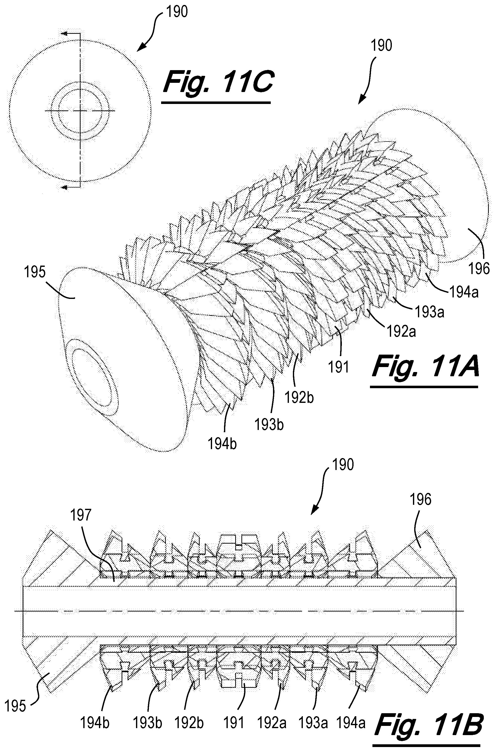
[0089] FIGS. 11A to 11C are respectively perspective, sectional and end views of an apparatus according to an alternative embodiment of the invention, shown in a collapsed condition;
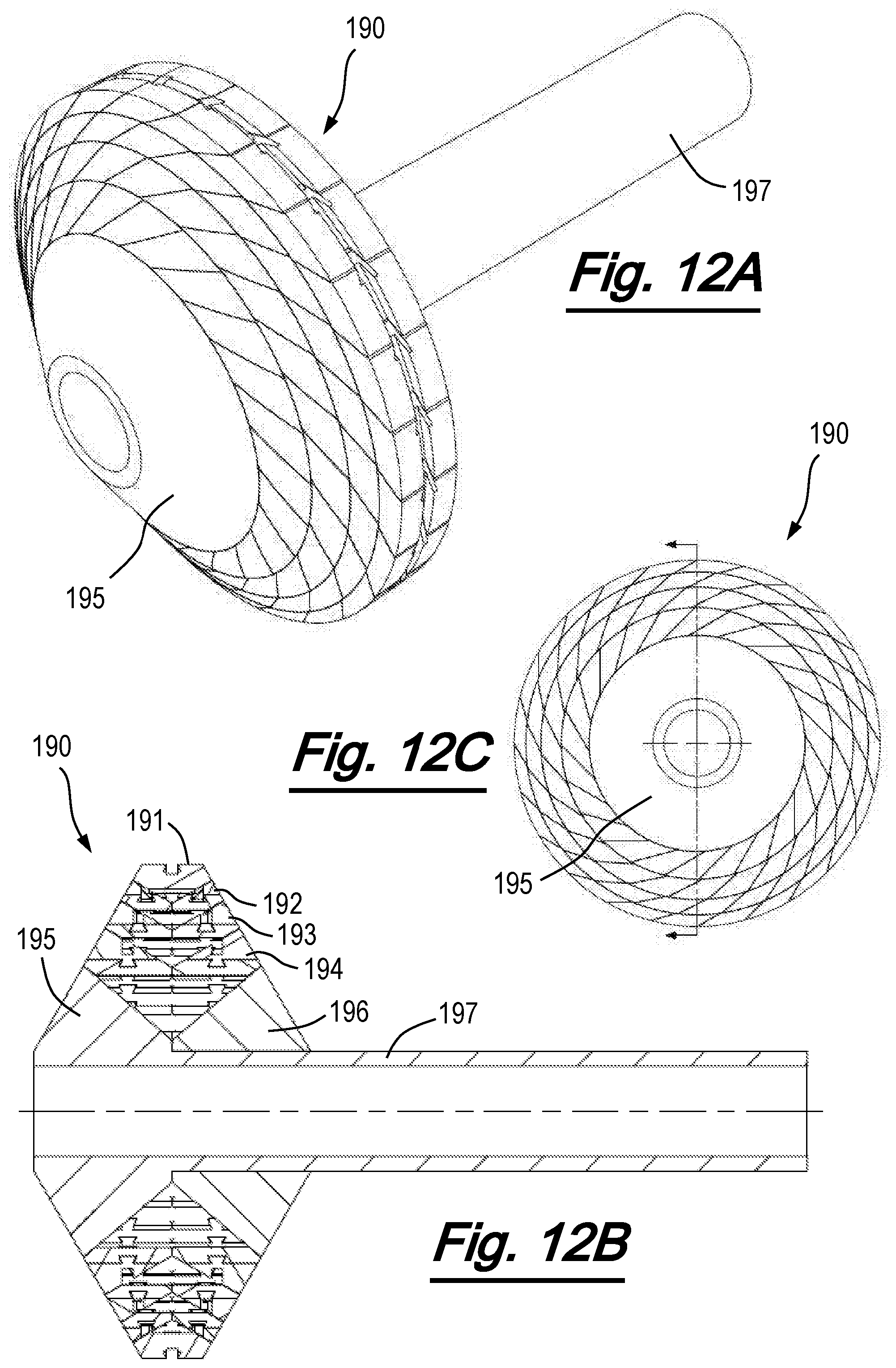
[0090] FIGS. 12A to 12C are respectively perspective, sectional and end views of the apparatus of FIGS. 11A to 11C, shown in an expanded condition;
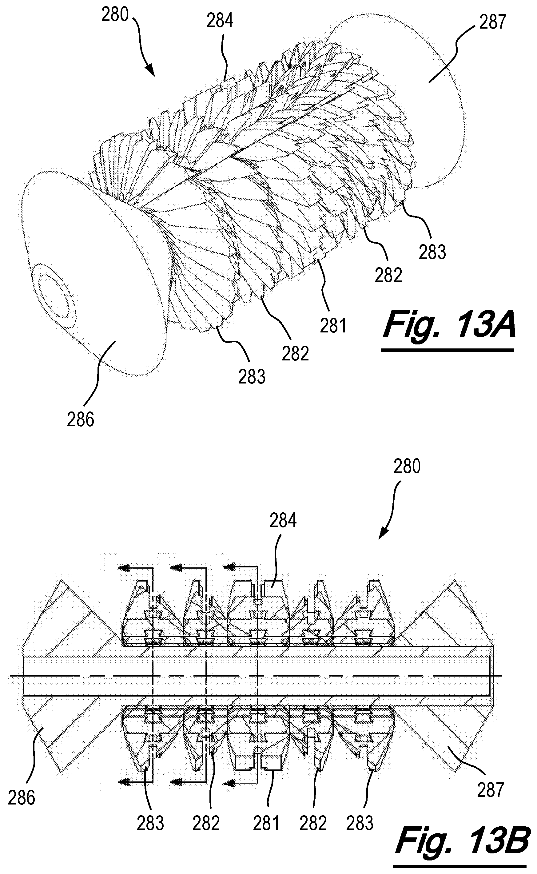
[0091] FIGS. 13A and 13B are respectively perspective and sectional views of an apparatus according to an alternative embodiment of the invention, shown in a collapsed condition;
[0092] FIGS. 14A to 14D are respectively perspective, first sectional, end, and second sectional views of the apparatus of FIGS. 13A and 13B, shown in an expanded condition;
[0093] FIG. 15 is a geometric representation of a centre element of the apparatus of FIGS. 13A and 13B, shown from one side;
[0094] FIGS. 16A to 16F are respectively first to fourth perspective, first end, and second end views of a centre element of the apparatus of FIGS. 13A and 13B;
[0095] FIGS. 17A and 17B are respectively perspective and sectional views of a patch apparatus according to an embodiment of the invention, shown in a collapsed condition;
[0096] FIGS. 18A and 18B are respectively perspective and sectional views of the apparatus of FIGS. 17A and 17B, shown in an expanded condition;
[0097] FIG. 19 is a side view of an apparatus according to an alternative embodiment of the invention in a first, collapsed condition;
[0098] FIG. 20 is a side view of the apparatus of FIG. 19 a second, collapsed condition;
[0099] FIGS. 21A and 21B are respectively plan and isometric views of an element of the apparatus of FIGS. 19 and 20; and
[0100] FIGS. 22A and 22B are respectively plan and isometric views of a second element of the apparatus of FIGS. 19 and 20.
DETAILED DESCRIPTION OF PREFERRED EMBODIMENTS
[0101] Referring firstly to FIGS. 1A to 4F, the principles of the invention will be described with reference to an expanding apparatus which is useful for understanding the invention and its embodiments. In the arrangement of FIGS. 1A to 4F, the expanding apparatus, generally depicted at 10, comprises an expanding ring structure configured to be expanded from a first collapsed or unexpanded condition (shown in FIGS. 1A to 1D) and a second expanded condition (shown in FIGS. 2A to 2D). The apparatus of this and other embodiments may be referred to as "expanding apparatus" for convenience, as they are operable to move to an expanded state from a normal collapsed state. However, the apparatus may equally be referred to as a collapsing apparatus, or an expanding or collapsing apparatus, as they are capable of being expanded or collapsed depending on operational state.
[0102] The expanding apparatus 10 comprises a plurality of elements 12 assembled together to form a ring structure 11. The elements 12 define an inner ring surface which is supported by the outer surface of cylinder 14. Each element comprises an inner surface 20, an outer surface 21 and first and second contact surfaces 22, 23. The first and second contact surfaces are oriented in non-parallel planes, which are tangential to a circle centred on the longitudinal axis of the apparatus. The planes converge towards the inner surface of the element. Therefore, each element is in the general form of a wedge, and the wedges are assembled together in a circumferentially overlapping fashion to form the ring structure 11. In use, the first and second contact surfaces of adjacent elements are mutually supportive.
[0103] As most clearly shown in FIGS. 3A and 3B, when the ring structure is expanded to its optimal outer diameter, the orientation planes of the first and second contact surfaces intersect an inner surface of the ring structure, and together with the longitudinal axis of the apparatus, the lines of intersection define a sector of a cylinder. In this case, the ring structure is formed from twenty-four identical elements, and the central angle .theta..sub.1 is 15 degrees. The angle described between the orientation planes of the first and second contact surface is the same as the central angle of the cylindrical sector, so that the elements are arranged rotationally symmetrically in the structure.
[0104] As shown in FIG. 3B, each element is based on a notional wedge-shaped segment of a ring centred on an axis, with each notional wedge-shaped segment being inclined with respect to the radial direction of the ring. The nominal outer diameter of the segment is at the optimum expansion condition of the ring (with radius shown at r.sub.1).
[0105] The orientation planes of the first and second contact surfaces of the element are tangential to a circle with radius r.sub.3 concentric with the ring at points t.sub.1, t.sub.2. The angle described between the tangent points is equal to the angle .theta..sub.1 of the segment. The orientation planes of the first and second contact surfaces of each notional wedge-shaped segment intersect one another on a radial plane P which bisects radial planes located at the tangent points (i.e. is at an angle of .theta..sub.1/2 to both). This intersection plane P defines the expanding and collapsing path of the segment.
[0106] In the configuration shown in FIGS. 1 and 2, notional wedge-shaped segments are modified by removal of the tips 29 of the wedges, to provide a curved or arced inner surface 20 with radius r.sub.2 when the ring is in its expanded condition shown in FIGS. 2A and 2D. The modification of the wedge-shaped elements can be thought of as an increase in diameter of an internal bore through the ring structure by 2(r.sub.2-r.sub.3), or a truncation of the inner diameter. This change in the inner diameter from the notional inner diameter r.sub.3 to which the contact surfaces are tangential to a truncated inner diameter r.sub.2, has the effect of changing an angle between the contact surfaces and the radial plane from the centre of the ring. Taking angle .theta..sub.2 to be the angle described between the contact surface and a radial plane defined between the centre point of the ring structure and the point at which the orientation surface meets or intersects a circle at the radial position of the inner surface, .theta..sub.2 is changed in dependence on the amount by which the segment has its inner diameter truncated. For the notional wedge shaped segment, the orientation planes of the contact surfaces are tangential to a circle at the inner diameter at r.sub.3 (i.e. angle .theta..sub.2 is 90 degrees). For the modified elements 12, the orientation planes of the contact surfaces instead intersect a circle at the (increased) inner diameter at r.sub.2 and are inclined at a reduced angle .theta..sub.2.
[0107] The angle .theta..sub.2 at which the segment is inclined is related to the amount of material removed from the notional wedge-shaped segment, but is independent from the central angle .theta..sub.1 of the wedge. Angle .theta..sub.2 is selected to provide element dimensions suitable for manufacture, robustness, and fit within the desired annular volume and inner and outer diameters of the collapsed ring. As the angle .theta..sub.2 approaches 90 degrees, a shallower, finer wedge profile is created by the element, which may enable optimisation of the collapsed volume of the ring structure. Although a shallower, finer wedge profile may have the effect of reducing the size of the gaps created at the inner surface of the ring in the collapsed condition and/or enabling a more compact collapsed condition, there are some consequences. These include the introduction of flat sections at the inner surfaces of the elements, which manifest as spaces at the inner diameter of the ring when in an expanded or partially expanded condition. When .theta..sub.2=90 degrees, all the segments are purely tangential to inner diameter, the collapsed volume for a given outer diameter and inner diameter is most efficient, but the inner surface of the ring structure is polygonal with flat sections created by each segment. In some configurations, these flat sections may be undesirable. There may also be potential difficulties with manufacture of the elements and robustness of the elements and assembled ring structure. However, in many applications, where the profile of the inner surface of the expanded ring is not critical, for example when the inner diameter of the ring structure is floating, and/or the true inner diameter is defined by an actuation wedge profile rather than the inner surface of the ring, this compromise may not be detrimental to the operation of the apparatus, and the reduced collapse volume may justify an inclination angle .theta..sub.2 of (or approaching) 90 degrees.
[0108] In the apparatus of FIGS. 1 to 4, the angle .theta..sub.2 is 75 degrees. Relaxing .theta..sub.2 to a reduced angle provides a smooth outer diameter and inner diameter profile to the expanded ring, as a portion of the inner circular arc is retained at the expense of slightly increased collapsed volume. It should be noted that the angle .theta..sub.2 is independent from the angle .theta..sub.1. Where the ring structure is desired to have a circular inner surface, preferred arrangements may have an angle .theta..sub.2 which is in the range of (90 degrees-2.theta..sub.1) to 90 degrees inclusive, and particularly preferred arrangements have an angle .theta..sub.2 in the range of 70 degrees to 90 degrees (most preferably in the range of 73 degrees to 90 degrees). In general, to provide sufficient truncation of the inner diameter to retain a useful portion of an inner arc and provide a smooth inner surface to the ring structure, a maximum useful value of .theta..sub.2 is (90 degrees-.theta..sub.1/2). This would be 82.5 degrees in the described arrangements.
[0109] In other configurations, also in accordance with embodiments of the invention (and as will be described below) the geometry of the notional wedge-shaped segments forming the elements may be unmodified (save for the provision of functional formations such as for interlocking and/or retention of the elements), without the removal of material from the tip of the notional wedge-shaped segments. Such embodiments may be preferred when there is no requirement for the ring structure to have a circular inner surface.
[0110] As most clearly shown in FIGS. 4A to 4F, the first and second contact surfaces of the element have corresponding interlocking profiles 24 formed therein, such that adjacent elements can interlock with one another. In this case, the interlocking profiles comprise a dovetail groove 25 and a corresponding dovetail tongue 26. The interlocking profiles resist circumferential and/or radial separation of the elements in the ring structure, but permit relative sliding motion between adjacent elements. The interlocking profiles also facilitate smooth and uniform expansion and contraction of the elements during use. It will be appreciated that alternative forms of interlocking profiles, for example comprising recesses and protrusions of other shapes and forms, may be used within the scope of the invention.
[0111] The elements are also provided with inclined side wall portions 27, which facilitate deployment of the apparatus in use. The side wall portions are formed in an inverted cone shape which corresponds to the shape and curvature of the actuating cone wedges profiles when the apparatus is in its maximum load condition (typically at its optimum expansion condition).
[0112] Each element is also provided with a groove 28, and in the assembled ring structure, the grooves are aligned to provide a circular groove which extends around the ring. The groove accommodates a biasing element (not shown), for example a spiral retaining ring of the type marketed by Smalley Steel Ring Company under the Spirolox brand, or a garter spring. In this case, the biasing means is located around the outer surface of the elements, to bias the apparatus towards the collapsed condition shown in FIGS. 1A to 1D. Although one groove for accommodating a biasing means is provided in this embodiment, in alternative embodiments of the apparatus, multiple grooves and biasing means may be provided.
[0113] The apparatus 10 comprises a wedge member 16, which in this case is an annular ring having a conical surface 18 opposing one side of the ring structure 11. The wedge angle corresponds with the angle of the inclined conical side walls 27 of the elements. A corresponding wedge shaped profile (not shown) is optionally provided on the opposing side of the ring structure to facilitate expansion of the ring elements. In alternative embodiments of the invention this optional additional wedge may be substituted with an abutment shoulder.
[0114] Operation of the expansion apparatus will now be described. In the first, collapsed or unexpanded condition, shown most clearly in FIG. 10, the elements are assembled in a ring structure 11 which extends to a first outer diameter. In this embodiment, and as shown in FIGS. 1B and 10, the wedge member 16 defines the maximum outer diameter of the apparatus in the first condition. The elements are biased towards the unexpanded condition by a spiral retaining ring (not shown), and are supported on the inner surface by the outer surface of the cylinder 14.
[0115] In use, an axial actuation force is imparted on the wedge member 16. Any of a number of suitable means known in the art can be used for application of the axial actuation force, for example, the application of a force from an outer sleeve positioned around the cylinder. The force causes the wedge member 16 to move axially with respect to the cylinder, and transfer a component of the axial force onto the recessed side wall of the elements. The angle of the wedge transfers a radial force component to the elements 12, which causes them to slide with respect to one another along their respective contact surfaces.
[0116] The movement of the expanding elements is tangential to a circle defined around the longitudinal axis of the apparatus. The contact surfaces of the elements mutually support one another before, during, and after expansion. The radial position of the elements increases on continued application of the axial actuation force until the elements are located at a desired outer radial position. This radial position may be defined by a controlled and limited axial displacement of the wedge member, or alternatively can be determined by an inner surface of a bore or tubular in which the apparatus is disposed.
[0117] FIGS. 2A to 2D show clearly the apparatus in its expanded condition. At an optimal expansion condition, shown in FIGS. 2B and 2D, the outer surfaces of the individual elements combine to form a complete circle with no gaps in between the individual elements. The outer surface of the expansion apparatus can be optimised for a specific diameter, to form a perfectly round expanded ring (within manufacturing tolerances) with no extrusion gaps on the inner or outer surfaces of the ring structure. The design of the expansion apparatus also has the benefit that a degree of under expansion or over expansion (for example, to a slightly different radial position) does not introduce significantly large gaps.
[0118] It is a feature of the invention that the elements are mutually supported before, throughout, and after the expansion, and do not create gaps between the individual elements during expansion or at the fully expanded position. In addition, the arrangement of elements in a circumferential ring, and their movement in a plane perpendicular to the longitudinal axis, facilitates the provision of smooth side faces or flanks on the expanded ring structure. With deployment of the elements in the plane of the ring structure, the overall width of the ring structure does not change. This enables use of the apparatus in close axial proximity to other functional elements.
[0119] The apparatus has a range of applications, some of which are illustrated in the following example embodiments. However, additional applications of the apparatus are possible which exploit its ability to effectively perform one or more of blocking or sealing an annular path; contacting an auxiliary surface; gripping or anchoring against an auxiliary surface; locating or engaging with radially spaced profiles; and/or supporting a radially spaced component.
[0120] The present invention extends the principles described above to multi-stage or telescopic expansion apparatus, which have applications to systems in which an increased expansion ratio is desirable. The following embodiments of the invention describe examples of such apparatus.
[0121] Referring now to FIGS. 5A to 6C, there is shown a two-stage expansion apparatus in accordance with an embodiment of the invention. FIGS. 5A to 5C are respectively perspective, longitudinal sectional, and end views of the apparatus in a first, collapsed condition. FIGS. 6A to 6C are equivalent views of the apparatus in an expanded condition. The apparatus, generally depicted at 170, comprises an expansion assembly 171 formed from three ring structures 172, 173a, 173b, each of which is formed from separate elements in the manner described with reference to FIGS. 1 to 4. The ring structures 172, 173a, 173b are disposed on a mandrel 174 between a wedge portion 175 which is fixed on a mandrel, and a moveable cone wedge member 176. An inner ring structure 172 is formed from a number of individual elements 177 assembled together. The elements 177 are similar to the elements 12, and their form and function will understood from FIGS. 1 to 4 and their accompanying description.
[0122] FIG. 7 is a geometric representation of a centre element of the apparatus of FIGS. 5A to 5C, shown from one side, and FIGS. 8A to 8F are respectively first perspective, second perspective, plan, first end, lower, and second end views of a centre element 177. The Figures show the inner and outer surfaces, first and second contact surfaces, interlocking profiles, and grooves for retaining circumferential springs which are equivalent in form and function to the features of the elements 12. Biasing means in the form of a circumferential spring retains the centre ring structure in its collapsed condition.
[0123] Disposed on either side of the centre ring structure are first and second outer ring structures 173a, 173b in the form of wedge ring structures. The wedge ring structures are also assembled from an arrangement of elements which, again, are similar in form and function to the elements 12. However, instead of providing an outer surface which is substantially parallel to the longitudinal axis of the apparatus, the outer surfaces of the outer elements are inclined to provide respective wedge surfaces 178a, 178b which face the centre ring structure 172.
[0124] FIG. 9 is a geometric representation of an outer element 182 of the apparatus of FIGS. 5A to 5C, shown from one side, and FIGS. 10A to 10H are respectively first perspective, second perspective, third perspective, fourth perspective, plan, first end, lower, and second end views of an outer element 182. The Figures show the inner and outer surfaces 183, 184, first and second contact surfaces 185, 186, interlocking profiles 187, 188, and grooves 189 for retaining circumferential springs which are equivalent in form and function to the features of the elements 12. In the assembled ring structure, the outer elements and the centre elements are nested with one another, and the outer surfaces 184 of the outer elements define respective wedge profiles for corresponding centre elements 177 during a first expansion stage as will be described below. Biasing means in the form of a circumferential spring retains the outer rings structure in their collapsed conditions, with the sequencing of the expanding and collapsing movement controlled by the selection of the relative strengths of the biasing means of the centre ring and the outer rings.
[0125] In a first, collapsed condition, the elements of the centre ring structure and the elements of the first and second outer ring structures, have a maximum outer diameter which is less than or equal to the outer diameter of the wedge profile 175 and wedge member 176.
[0126] Operation of this embodiment of the apparatus will be described, with additional reference to FIGS. 6A to 6C.
[0127] In common with other embodiments, the apparatus is actuated to be radially expanded to a second diameter by an axial actuation force which moves the cone wedge member 176 on the mandrel and relative to the ring structure. The axial actuation force acts through the ring structures 173a, 173b to impart axial and radial force components onto the elements. Radial expansion of the ring structures 173a, 173b is resisted by their respective circumferential springs arranged in grooves 179, and the forces are transferred to the centre ring structure 172. The elements of the centre ring experience an axial force from the wedge surfaces 178a, 178b of the elements of the outer ring structures, which is translated to a radial expansion force on the elements of the centre ring structure 172. The radial expansion force overcomes the retaining force of a circumferential spring in the groove 181 (which is selected to be weaker than the retaining forces of the circumferential springs in the outer rings), and the elements slide with respect to one another to expand the centre ring structure as the outer ring structures move together.
[0128] The pair of outer rings is brought together until the elements of the centre ring structure are expanded on the wedge profiles of the outer elements. In this condition, the first expansion stage is complete, but the centre ring is not yet expanded to its optimum outer diameter.
[0129] The elements of the wedge ring structure 173a, 173b are symmetrical about a centre line of the ring structure, and are configured to be brought into abutment with one another under a central line under the centre segments. This design defines an end point of the axial travel of an outer ring structure, and prevents its elements from over-travelling. This abutment point changes the mode of travel of an outer ring from axial displacement (during which it expands an adjacent ring which is disposed towards the centre of the apparatus by a wedging action) into a tangential sliding movement of elements within the ring, to cause it to expand radially on the apparatus.
[0130] The outer ring structures 173a and 173b have been brought together into abutment, and further application of an axial actuation force causes the elements of the respective outer ring structures to experience a radial force component from the wedge 175 and the wedge profile 176. The radial force directs the elements of the outer ring structures to slide with respect to one another into radially expanded conditions. The radial movement of the elements of the outer rings is the same as the movement of the elements of the centre ring structure and the elements described with reference to previous embodiments: the elements slide with respect to one another in a tangential direction, while remaining in mutually supportive planar contact. As the outer ring structures expand, a radial force is imparted to the elements of the centre ring, which continue to slide with respect to one another in a tangential direction to their fully expanded condition.
[0131] The resulting expanded condition is shown in FIGS. 6A to 6C. The apparatus forms an expanded ring structure which is solid, with no gaps between its elements, and which has a smooth circular outer surface at its full expanded condition. In addition, both of the annular surfaces or flanks of the expanded ring are smooth. The outer diameter of the expanded ring is significantly greater than the outer diameter of the ring structures (and wedges) in their collapsed state, with the increased expansion resulting from the two stage mechanism.
[0132] Retaining the axial force on the wedges will retain the ring structure in an expanded condition, and a reduction in the axial force to separate the wedge profiles enables the inner and outer ring structures to collapse under the retention forces of their respective spring elements.
[0133] Collapsing of the apparatus to a collapsed condition is achieved by releasing the axial actuation force. The sequence of collapsing is the reverse of the expanding process: the outer ring structures are collapsed first under the higher retaining forces of their respective biasing springs. Collapse of the outer rings also brings the centre ring structure from is fully expanded condition to an intermediate condition. Further separation of the wedge profiles collapses the centre ring structure under the retaining force of its biasing spring, back to the collapsed position shown in FIGS. 5A and 5B.
[0134] The principles of the two-stage expansion mechanism can be extended to other multi-stage expanding and collapsing apparatus. FIGS. 11A to 12C show such an apparatus, which has a four-stage expansion system. FIGS. 11A to 11C are respectively perspective, longitudinal sectional, and end views of the apparatus in a first, collapsed condition. FIGS. 12A to 12C are equivalent views of the apparatus in an expanded condition. The apparatus, generally shown at 190, is similar to the apparatus 170, and its form and function will be understood from FIGS. 5 to 10 and the accompanying description. However, the apparatus 190 differs in that it comprises a centre ring structure 191 formed from individual elements, and three pairs of outer ring structures 192, 193, 194 (each consisting of upper and lower ring structures 192a, 192b, 193a, 193b, 194a, 194b) disposed on a mandrel 197 between wedge 195 and wedge profile 196.
[0135] In successive stages of actuation, the centre ring structure 191 is deployed to a first intermediate expanded state, and first, second, and third pairs of outer ring structures are deployed to their radially expanded states, from the inside of the apparatus adjacent to the centre ring, to the outside. At each stage, the centre ring structure is deployed to successive intermediate expanded states, until it is fully expanded as shown in FIGS. 12A to 12C. The outer diameter of the expanded ring is significantly greater than the outer diameter of the ring structures (and wedges) in their collapsed state, with the increased expansion resulting from the four-stage mechanism. Sequencing of the expansion is designed to be from the inside to the outside by selection of biasing springs with successively higher retaining forces (moving from the inside or centre of the apparatus to the outermost rings). Collapsing of the apparatus to a collapsed condition is achieved by releasing the axial actuation force, and the sequence of collapsing is the reverse of the expanding process.
[0136] FIGS. 13A to 14D show a multi-stage expanding and collapsing system in accordance with an alternative embodiment of the invention. FIGS. 13A and 13B are respectively perspective and longitudinal sectional views of the apparatus in a first, collapsed condition. FIGS. 14A and 14B are equivalent views of the apparatus in an expanded condition; FIG. 14C is an end view and FIG. 14D is a section through line D-D of FIG. 14B. The apparatus, generally shown at 280, is similar to the apparatus 170 and 190, and its form and function will be understood from FIGS. 5 to 12 and the accompanying description. However, the apparatus 280 differs in that it comprises pars of ring structures 281, 282, 283 formed from individual elements with geometry different from those of previous embodiments.
[0137] FIG. 15 is a geometric representation of a centre element of the apparatus of FIGS. 13A and 13B, shown from one side, and FIGS. 16A to 16F are respectively first perspective, second perspective, plan, first end, lower, and second end views of a centre element 284. The Figures show the inner and outer surfaces, first and second contact surfaces, interlocking profiles, and grooves for retaining circumferential springs which are equivalent in form and function to the features of the elements 12 and 177.
[0138] Each element is effectively a segment of a ring which has its nominal outer diameter at the optimum expansion condition of the ring, but which has been inclined at an angle .theta..sub.2 with respect to a radial direction. However, in this embodiment, .theta..sub.2 is 90 degrees, and a shallower, finer wedge profile is created by the element. The orientation planes of the contact surfaces are tangential to the circle described by the inner surface of the ring structure in its collapsed condition. This enables optimisation of the collapsed volume of the ring structure, by reducing the size of the gaps created at the inner surface of the ring in the collapsed condition and enabling a more compact collapsed condition. These include the introduction of flat sections 285 at the inner surface of the elements (visible in FIG. 14D), which manifest as spaces at the inner diameter of the ring when in an expanded or partially expanded condition. In the construction shown, the profile of the inner surface of the expanded ring is not critical, as the inner diameter of the ring structure is floating, and the true inner diameter is defined by the actuation wedge profiles 286, 287 rather than the inner surface of the ring. The spaces are therefore not detrimental to the operation of the apparatus, and the apparatus benefits from a reduced collapse volume.
[0139] The elements 284 also differ from the elements of previous embodiments of the invention in that the interlocking profiles formed by grooves and tongues are inverted, such that the groove 288 is in the inner surface of the element, and the tongue 289 is in the outer surface. This increases the engagement length between adjacent elements.
[0140] The elements 290 of the ring structures 282 and 283 are similarly formed, with angle .theta..sub.2 at 90 degrees, with the orientation planes of their contact surfaces being tangential to the circle described by the inner surface of the ring structure in its collapsed condition.
[0141] It should be noted that in other embodiments, different angles .theta..sub.2 may be adopted, including those which are in the range of 80 degrees to 90 degrees (most preferably tending towards 90 degrees).
[0142] Operation of the expanding and collapsing apparatus is the same as that described with reference to FIGS. 11A to 12C, with the centre ring structure 281 being deployed to a first intermediate expanded state, and first and second pairs of outer ring structures being deployed to their radially expanded states, in sequence from the inside of the apparatus adjacent to the centre ring 281, to the outside. Sequencing of the expansion is designed to be from the inside to the outside by selection of biasing springs with successively higher retaining forces (moving from the inside or centre of the apparatus to the outermost rings). Collapsing of the apparatus to a collapsed condition is achieved by releasing the axial actuation force, and the sequence of collapsing is the reverse of the expanding process.
[0143] The apparatus 280, by virtue of the compact collapsed inner volumes achievable with the finer wedge profiles, is capable of increased expansion ratios. In this example, the apparatus 280 is configured to have the same expansion ratio as the apparatus 190, with only two pairs of expanding ring structure compared with the three pairs in the apparatus 190. This reduces the axial length of the apparatus and greatly reduces the number of parts required.
[0144] The particularly high expansion ratios achieved with the multi-stage expansion embodiments of the invention enable application to a range of operations. For example, the apparatus may form part of a mechanically actuated, high expansion, production packer or high expansion annular flow barrier. Particular applications include (but are not limited to) cement stage packers or external casing packers for openhole applications.
[0145] The expansion ratios achievable also enable use of the apparatus in through-tubing applications, in which the apparatus is required to pass through a tubing or restriction of a first inner diameter, and be expanded into contact with a tubing of a larger inner diameter at a greater depth in the wellbore. For example, the apparatus may be used in a high expansion retrievable plug, which is capable of passing through a production tubing to set the plug in a larger diameter liner at the tailpipe.
[0146] An alternative application of the multi-stage expansion apparatus of FIGS. 5 and 6 to a fluid conduit patch tool and apparatus will now be described with reference to FIGS. 13A to 14B. A typical patching application requires the placement and setting of a tubular section over a damaged part of a fluid conduit (such as a wellbore casing). A patch tool comprises a tubular and a pair of setting mechanisms axially separated positions on the outside of the conduit for securing the tubular to the inside of the fluid conduit. It is desirable for the setting mechanisms to provide an effective flow barrier, but existing patch systems are often deficient in providing a fluid-tight seal with the inner surface of the fluid conduit, and are limited in their expansion capabilities.
[0147] FIGS. 13A and 13B show a high expansion patch tool, generally depicted at 210, from perspective and longitudinal sectional views shown in a collapsed, run position. FIGS. 14A and 14B are equivalent views of the apparatus in an expanded condition.
[0148] The patch tool comprises a tubular section 211, and a pair of expansion assemblies 212a, 212b (together 212) in axially separated positions on the section. The distance between the assemblies 212a, 212b is selected to span the damaged section of a fluid conduit to be patched. Each of the assemblies 212 comprises a pair of expansion apparatus 213a, 213b, disposed on either side of an elastomeric seal element 214. The expansion apparatus 213 are similar in form and function to the expansion apparatus 170, and their operation will be described with reference to FIGS. 5 and 6. Each comprises a centre ring structure and a pair of outer ring structures. A pair of cone wedge members 215 is provided on either side of the expansion apparatus 213.
[0149] The elastomeric seal elements 214 are profiled such that an axially compressive force deforms the elastomeric material, and brings first and second halves 214a, 214b of the seal element together around a deformation recess 216.
[0150] The patch tool is, like other embodiments of the invention, configured to be actuated by an axial force. The axial force acts to radially expand the expansion apparatus 213 in the manner described with reference to FIGS. 5 and 6, and into contact with the fluid conduit to be patched. The elastomeric seals are deformed by the axial force via the cone wedges 215, to change shape and fill an enclosed annular space formed between a pair of expansion apparatus 213a, 213b. The expanded condition is shown in FIGS. 14A and 14B.
[0151] The expansion apparatus may provide sufficient frictional force with the inner surface of the conduit being patched to secure the patch tool in the conduit. This may be facilitated by providing engaging profiles on the expansion apparatus. For example, unidirectional or bidirectional arrangements of ridges and grooves may be provided to engage a surrounding surface and resist movement of the apparatus. Alternatively (or in addition), separate anchor mechanisms may be provided.
[0152] The patch tool 210 provides a pair of effective seals which are fully supported by the expansion apparatus, each of which forms a solid anti-extrusion ring.
[0153] FIGS. 19 to 22B show a multi-stage expanding and collapsing system in accordance with an alternative embodiment of the invention. FIGS. 19 and 20 are respectively side views of the apparatus in a first, collapsed condition and second expanded condition. FIGS. 21A and 21B are respectively plan and isometric views of the a first set of elements of the apparatus; FIGS. 22A and 22B are respectively plan and isometric views of a second set of elements of the apparatus. The apparatus, generally shown at 380, is similar to the apparatus 170, 190, and 280, with a central ring structure 381 formed from an assembly of elements 384, and two pairs of ring structures 382a, 382b (together 382), 383a and 383b (together 383). The form and function of the apparatus will be understood from FIGS. 5 to 18 and the accompanying description. However, the apparatus 380 differs in that it comprises pairs of ring structures 382, 383 formed from individual elements with geometry different from those of previous embodiments.
[0154] FIGS. 21A and 21B are respectively plan and isometric views of an element 385, from which the outer ring structures 383a, 383b are assembled. FIGS. 22A and 22B are respectively plan and isometric views of an element 386, from which the intermediate ring structures 382a, 382b are assembled. The Figures show the outer surfaces, first contact surfaces, and interlocking tongues. The external profiles of the elements 385, 386 are modified by provision of additional chamfers 387, 388. These chamfers modify the external profile of the elements, so that when assembled into a ring, the inward facing flank (i.e. the flank facing the centre ring) has an at least partially smoothed conical surface. This facilitates the deployment of the apparatus; the smoother conical surface improves the sliding action of the elements the centre ring 381 on the conical profiles of the rings 382a, 382b as the elements are brought together to expand the centre ring. Similarly, the smoothed inward facing flank of the rings 383a, 383b facilitate the sliding of the elements 382a of the rings 382a, 383b during their expansion. The smoothed cones assist a supporting ring in punching under the adjacent ring with a smooth action,
[0155] The outer surfaces 389, 390 of the elements 385, 386 are profiled such that the ring structures 382, 383 define smooth conical surfaces on their outward facing flanks when in their expanded condition. These conical surfaces combine in the assembled, expanded apparatus, to provide a substantially or fully smooth surface which is suitable for abutment with and/or support of an adjacent element such as an elastomer.
[0156] The elements 385, 386 also differ from the elements of previous embodiments of the invention in that the biasing means in the form of garter springs are not mounted in external grooves. Instead, apertures 391, 392 are provided in the elements for receiving the garter springs (or an alternative biasing means). The garter spring may be threaded through each element and then joined to make a continuous loop upon assembly. By providing the biasing means in-board of the external surface, it may be better protected from damage. In addition, the external profile of the elements is simplified and is more supportive of adjacent elements as supportive as possible. This configuration also facilitates location of the biasing means directly over the dovetail feature, so that the biasing force acts centrally to reduce the likelihood of canting and jamming.
[0157] The invention may be used to provide an anti-extrusion ring or back-up ring for a wide range of expanding, radially expanding or swelling elements. For example, the apparatus may be used as an anti-extrusion or back-up ring for compressible, inflatable and/or swellable packer systems. Alternatively, or in addition, the expansion apparatus may provide support or back-up for any suitable flow barrier or seal element in the fluid conduit. This may function to improve the integrity of the fluid barrier or seal, and/or enable a reduction in the axial length of the seal element or flow barrier without compromising its functionality. A particular advantage is that equipment incorporating the expansion apparatus of the present invention can be rated to a higher maximum working pressure.
[0158] It will be appreciated that a "single stage" expansion apparatus, for example as described with reference to FIGS. 1 to 4, may be used in a patch tool and method of use. Indeed, in some applications this may desirable, as the resulting patched tubular can have an inner diameter close to the inner diameter of the fluid conduit that has been patched, mitigating the reduction to bore size. However, the patch tool 210 has the advantage of high expansion for a slim outer diameter profile, which enables the tool to be run through a restriction in the fluid conduit, to patch a damaged part of the conduit which has a larger inner diameter than the restriction. For example, the patching tool could be run through a part of the fluid conduit that has already been patched, either by conventional means or by a patching tool based on a single-stage expansion apparatus. Higher expansion ratio patching tools could be used, based on expansion apparatus having three or more stage deployment.
[0159] In the foregoing embodiments, where the expanding and collapsing apparatus is used to create a seal, the seal is typically disposed between two expanding ring structures. In alternative embodiments (not illustrated), an expanding ring structure can be used to provide a seal, or at least a restrictive flow barrier directly. To facilitate this, the elements which are assembled together to create the ring structures may be formed from metal or a metal alloy which is fully or partially coated or covered with a polymeric, elastomeric or rubber material. An example of such a material is a silicone polymer coating. All surfaces of the elements may be coated, for example by a dipping or spraying process, and the mutually supportive arrangement of the elements keeps them in compression in their operating condition. This enables the ring structures themselves to function as flow barriers, and in some applications, a seal created is sufficient to seal against differential pressures to create a seal.
[0160] Alternatively, or in addition, the elements themselves may be formed from a compressible and/or resilient material, such as an elastomer, rubber or polymer.
[0161] In a further alternative embodiment of the invention (not illustrated) the characteristics of the expanding/collapsing apparatus are exploited to provide a substrate which supports a seal or other deformable element. As described herein, the expanded ring structures of the invention provide a smooth circular cylindrical surface at their optimum expanded conditions. This facilitates their application as a functional endo-skeleton for a surrounding sheath. In one example application, a deformable elastomeric sheath is provided over an expanding ring structure 10, as described with reference to FIGS. 5A to 6C. When in its collapsed condition, the sheath is supported by the collapsed ring structures. The ring structure are deployed in the manner described with reference to FIGS. 1 and 2, against the retaining force of the circumferential spring element and any additional retaining force provided by the sheath, and the sheath is deformed to expand with the ring structure into contact with the surrounding surface. The sheath is sandwiched between the smooth outer surface of the ring structure and the surrounding surface to create a seal.
[0162] It will be appreciated that a multistage expanding apparatus (for example the apparatus 170) could be used as an endo-skeleton to provide structural support for components other than deformable sheaths, including tubulars, expanding sleeves, locking formations and other components in fluid conduits or wellbores.
[0163] The multi-stage expansion apparatus of the invention may be applied to a high expansion packer or plug, and in particular a high expansion retrievable bridge plug. The ring structure may be arranged to provide a high-expansion anti-extrusion ring for a seal element of a plug. Alternatively, or in addition, elements of ring structures of the apparatus may be provided with engaging means to provide anchoring forces which resist movement in upward and/or downward directions. The elements of the rings structure may therefore function as slips, and may in some cases function as an integrated slip and anti-extrusion ring. Advantages over previously proposed plugs include the provision of a highly effective anti-extrusion ring; providing an integrated slip and anti-extrusion assembly, which reduces the axial length of the tool; providing slips with engaging surfaces which extend around the entire circumference of the tool to create an enlarged anchoring surface, which enables a reduction in the axial length of the slips for the same anchoring force; the ability of slips of a ring structure of one particular size to function effectively over a wider range of tubular inner diameters and tubing weights/wall thicknesses.
[0164] Alternatively or in addition, the apparatus may be used to anchor any of a wide range of tools in a wellbore, by providing the surfaces of the element with engaging means to provide anchoring forces which resist movement in upward and/or downward directions.
[0165] The invention also has benefits in creating a seal and/or filling an annular space, and an additional example application is to downhole locking tools. A typical locking tool uses one or more radially expanding components deployed on a running tool. The radially expanding components engage with a pre-formed locking profile at a known location in the wellbore completion. A typical locking profile and locking mechanism includes a recess for mechanical engagement by the radially expanding components of the locking tool. A seal bore is typically provided in the profile, and a seal on the locking tool is designed to seal against the seal bore.
[0166] One advantage of the application of the invention to locking mechanism is that the locking mechanism may be provided with an integrated seal element between two expanding sring structures, and does not require a seal assembly at an axially separated point. This enables a reduction in the length of the tool. The integrated seal is surrounded at its upper and lower edges by the surfaces of the ring structures, which avoid extrusion of the seal. In addition, each of the ring structures provides a smooth, unbroken circumferential surface which may engage a locking recess, providing upper and lower annular surfaces in a plane perpendicular to the longitudinal axis of the bore. This annular surface may be smooth and unbroken around the circumference of the ring structures, and therefore the lock is in full abutment with upper and lower shoulders defined in the locking profile. This is in contrast with conventional locking mechanisms which may only have contact with a locking profile at a number of discrete, circumferentially-separated locations around the device. The increased surface contact can support larger axial forces being directed through the lock. Alternatively, an equivalent axial support can be provided in a lock which has reduced size and/or mass.
[0167] Another advantage of this embodiment of the invention is that a seal bore (i.e. the part of the completion with which the elastomer creates a seal) can be recessed in the locking profile. The benefit of such configuration is that the seal bore is protected from the passage of tools and equipment through the locking profile. This avoids impact with the seal bore which would tend to damage the seal bore, reducing the likelihood of reliably creating a successful seal.
[0168] Similar benefits may be delivered in latching arrangements used in connectors, such as so called "quick connect" mechanisms used for latched connection of tubular components. A significant advantage of the invention in connection system applications is that the expansion apparatus forms a solid and smooth ring in an expanded latched position. An arrangement of radially split elements would, when expanded, form a ring with spaces between elements around their sides. In contrast, the provision of a continuous engagement surface on the expansion ring which provides full annular contact with the recess results in a latch capable of supporting larger axial forces. In addition, the by minimising or eliminating gaps between elements, the device is less prone to ingress of foreign matter which could impede the collapsing action of the mechanism. These principles may also be applied to subsea connectors such as tie-back connectors, with optional hydraulic actuation of their release mechanism.
[0169] Additional applications of the principles of the invention include variable diameter tools, examples of which include variable diameter drift tools and variable diameter centralising tools. The position a wedge member and a cooperating surface may be adjusted continuously or to a number of discrete positions, to provide a continuously variable diameter, or a number of discrete diameters.
[0170] The invention provides an expanding and collapsing apparatus and methods of use. The apparatus comprises a plurality of elements assembled together to form a ring structure oriented in a plane around a longitudinal axis. The ring structure is operable to be moved between an expanded condition and a collapsed condition on actuation by an axial force. The plurality of elements are operable to be moved between the expanded and collapsed conditions by sliding with respect to one another in the plane of the ring structure.
[0171] The invention provides an expanding and collapsing ring apparatus and method of use. The expanding and collapsing ring comprises a plurality of elements assembled together to form a ring structure oriented in a plane around a longitudinal axis. The ring structure is operable to be moved between a collapsed condition and a first expanded condition by movement of the plurality of elements on actuation by an axial force. The apparatus further comprises a secondary expanding and collapsing mechanism operable to move the ring structure between its collapsed condition or its first expanded conditions to a second expanded condition on actuation by an axial force. Applications of the invention include oilfield devices, including anti-extrusion rings, plugs, packers, locks, patching tools, connection systems, and variable diameter tools run in a wellbore.
[0172] The invention in its various forms benefits from the novel structure and mechanism of the apparatus. The invention also enables high expansion applications.
[0173] In addition, at an optimal expansion condition, shown in FIGS. 2B and 2D, the outer surfaces of the individual elements combine to form a complete circle with no gaps in between the individual elements, and therefore the apparatus can be optimised for a specific diameter, to form a perfectly round expanded ring (within manufacturing tolerances) with no extrusion gaps on the inner or outer surfaces of the ring structure. The design of the expansion apparatus also has the benefit that a degree of under expansion or over expansion (for example, to a slightly different radial position) does not introduce significantly large gaps.
[0174] It is a feature of the invention that the elements are mutually supported before, throughout, and after the expansion, and do not create gaps between the individual elements during expansion or at the fully expanded position. In addition, the arrangement of elements in a circumferential ring, and their movement in a plane perpendicular to the longitudinal axis, facilitates the provision of smooth side faces or flanks on the expanded ring structure. With deployment of the elements in the plane of the ring structure, the width of the ring structure does not change. This enables use of the apparatus in close axial proximity to other functional elements.
[0175] In addition, each of the ring structures provides a smooth, unbroken circumferential surface which may be used in engagement or anchoring applications, including in plugs, locks, and connectors. This may provide an increased anchoring force, or full abutment with upper and lower shoulders defined in a locking or latching profile, enabling tools or equipment be rated to a higher maximum working pressure.
[0176] Various modifications to the above-described embodiments may be made within the scope of the invention, and the invention extends to combinations of features other than those expressly claimed herein. In particular, the different embodiments described herein may be used in combination, and the features of a particular embodiment may be used in applications other than those specifically described in relation to that embodiment.
* * * * *
D00000
D00001
D00002
D00003
D00004
D00005
D00006
D00007
D00008
D00009
D00010
D00011
D00012

D00013

D00014

D00015

D00016

D00017

XML
uspto.report is an independent third-party trademark research tool that is not affiliated, endorsed, or sponsored by the United States Patent and Trademark Office (USPTO) or any other governmental organization. The information provided by uspto.report is based on publicly available data at the time of writing and is intended for informational purposes only.
While we strive to provide accurate and up-to-date information, we do not guarantee the accuracy, completeness, reliability, or suitability of the information displayed on this site. The use of this site is at your own risk. Any reliance you place on such information is therefore strictly at your own risk.
All official trademark data, including owner information, should be verified by visiting the official USPTO website at www.uspto.gov. This site is not intended to replace professional legal advice and should not be used as a substitute for consulting with a legal professional who is knowledgeable about trademark law.