Utility Post And Method Of Use
XUE; NING ; et al.
U.S. patent application number 16/416458 was filed with the patent office on 2019-11-21 for utility post and method of use. The applicant listed for this patent is ORIGIN POINT BRANDS, LLC. Invention is credited to DUANE E. LANGENWALTER, NING XUE.
| Application Number | 20190352927 16/416458 |
| Document ID | / |
| Family ID | 68534469 |
| Filed Date | 2019-11-21 |


| United States Patent Application | 20190352927 |
| Kind Code | A1 |
| XUE; NING ; et al. | November 21, 2019 |
UTILITY POST AND METHOD OF USE
Abstract
A utility post is provided that includes a first flange, a second flange, and a rib. The first flange resides in a plane and the second flange resides in the same plane. The rib is perpendicular to the plane. First, second, and third apertures are also provided, the first aperture defined through the first flange, the second aperture defined through the second flange, and the third aperture defined through the rib.
| Inventors: | XUE; NING; (DANBURY, CT) ; LANGENWALTER; DUANE E.; (MONROE, CT) | ||||||||||
| Applicant: |
|
||||||||||
|---|---|---|---|---|---|---|---|---|---|---|---|
| Family ID: | 68534469 | ||||||||||
| Appl. No.: | 16/416458 | ||||||||||
| Filed: | May 20, 2019 |
Related U.S. Patent Documents
| Application Number | Filing Date | Patent Number | ||
|---|---|---|---|---|
| 62673644 | May 18, 2018 | |||
| Current U.S. Class: | 1/1 |
| Current CPC Class: | E04H 17/1421 20130101; E04H 17/1434 20130101; E04H 17/20 20130101; E04H 2017/1452 20130101; E04H 17/22 20130101; E04H 17/08 20130101 |
| International Class: | E04H 17/20 20060101 E04H017/20; E04H 17/14 20060101 E04H017/14 |
Claims
1. A utility post, comprising: first and second flanges, a rib, the utility post defining a length, and one or more of the first flange, the second flange, and the rib residing along the length, the first and second flanges extending generally oppositely and away from the rib, the rib extending generally perpendicular to the first and second flanges, and a plurality of apertures defined through the first flange, the second flange, and the rib and disposed generally parallel to the length.
2. The utility post of claim 1, in which the first and second flanges are each planar.
3. The utility post of claim 1, in which the first and second flanges are coplanar.
4. The utility post of claim 1, in which adjacent apertures of the plurality of apertures defined through the first flange reside less than three and one-half inches apart.
5. The utility post of claim 4, in which adjacent apertures of the plurality of apertures defined through the second flange reside less than three and one-half inches apart and in which adjacent apertures of the plurality of apertures defined through the rib reside less than three and one-half inches apart.
6. The utility post of claim 1, in which one or more of the first flange, the second flange, and the rib are of substantially equal lengths.
7. The utility post of claim 1, in which the first flange, the second flange, and the rib are of substantially equal lengths.
8. The utility post of claim 1, in which the first flange and the second flange are integral and in which the rib is welded to the first and second flanges.
9. The utility post of claim 1, in which the utility post defines a length and in which one or more of the first flange, the second flange, and the rib terminate at a lower end that resides at an acute angle to the length.
10. A utility post, comprising: a first flange, the first flange extending in a first direction and residing in a first plane; a second flange, the second flange extending in a second direction and residing in a second plane, a rib, the rib being connected to the first flange and being perpendicular to the first plane; a first aperture, the first aperture defined through the first flange; a second aperture, the second aperture defined through the second flange; and a third aperture, the third aperture defined through the rib.
11. The utility post of claim 10, in which the first plane is coplanar with the second plane.
12. The utility post of claim 10, further including a fourth aperture defined through the first flange, the fourth aperture residing less than three and one-half inches below the first aperture.
13. The utility post of claim 10, in which at least two of the first flange, the second flange, and the rib are of substantially equal lengths.
14. The utility post of claim 10, further including plural additional apertures defined through and residing along the lengths of the first flange, the second flange, and the rib.
15. The utility post of claim 10, in which the first flange and the second flange are integral and in which the rib is welded to the first and second flanges.
16. The utility post of claim 13, in which the utility post defines a length and in which one or more of the first flange, the second flange, and the rib terminate at a lower end that resides at an acute angle to the length.
17. A method of constructing a fence, comprising the steps of: fixing a first utility post to the ground, fixing a second utility post to the ground a predetermined distance from the first utility post, wherein each of the first and second utility posts comprises first and second flanges, a rib, the utility post defining a length, and one or more of the first flange, the second flange, and the rib residing along the length, the first and second flanges extending generally oppositely and away from the rib, the rib extending generally perpendicular to the first and second flanges, and a plurality of apertures defined through the first flange, the second flange, and the rib and disposed generally parallel to the length. attaching a first upper rail between the first and second utility posts by use of fasteners disposed through one or more of the apertures defined through one of the first and second flanges of each respective utility post; attaching a first lower rail between the first and second utility posts by use of fasteners disposed through one or more of the apertures defined through one of the first and second flanges of each respective utility post; the first upper rail and the first lower rail defining a first plane between them on their first sides and a second plane between them on their opposite sides; connecting first plural vertical pickets to the first upper rail and the first lower rail on the first plane; and connecting second plural vertical pickets to the first upper rail and the first lower rail on the second plane.
18. The method of claim 16, further including the step of attaching an intermediate rail between the first and second utility posts and between the upper rail and the lower rail by use of fasteners disposed through one or more of the apertures defined through one of the first and second flanges of each respective utility post, and connecting the plural vertical pickets to the intermediate rail.
19. The method of claim 17, further including the step of connecting a vertical picket to the fence, upon a first side of the first utility post on the first plane, and connected a separate vertical picket to the fence upon a side opposite the first side of the first utility post on the second plane.
20. The method of claim 18, further including the steps of: fixing a third utility post to the ground a predetermined distance from the first utility post, and attaching a second upper rail between the first and third utility posts by use of fasteners disposed through one or more of the apertures defined through one of the first flange and the rib of each respective utility post, the second upper rail being perpendicular to the first upper rail.
Description
CROSS REFERENCE TO RELATED APPLICATIONS
[0001] This application claims the benefit of priority of U.S. Provisional Application Ser. No. 62/673,644, filed on May 18, 2018, which is incorporated herein in its entirety.
STATEMENT REGARDING FEDERALLY SPONSORED RESEARCH OR DEVELOPMENT
[0002] Not applicable.
THE NAMES OF PARTIES TO A JOINT RESEARCH AGREEMENT
[0003] Not applicable.
INCORPORATION-BY-REFERENCE OF MATERIALS SUBMITTED ON A COMPACT DISC OR AS A TEXT FILE VIA THE OFFICE ELECTRONIC FILING SYSTEM
[0004] Not applicable.
STATEMENT REGARDING PRIOR DISCLOSURES BY THE INVENTOR OR A JOINT INVENTOR
[0005] Not applicable.
BACKGROUND OF THE INVENTION
Field of the Invention
[0006] The present invention relates to a utility post and a method of using such a utility post and, more particularly, to a utility post that has been optimized for use as a fence post for a fence having horizontal rails that carry vertical pickets.
Description of the Related Art
[0007] Fences have been built of many and varied styles. Correspondingly, various fence post configurations have been used in the past, depending in part on the style of fence.
[0008] A particular fence style uses horizontal rails affixed to fence posts, with vertical pickets then attached to the horizontal rails. With this particular style of fence, though, a limitation arises if the builder desires to attach vertical pickets to both sides of the horizontal rails, in that the fence posts interrupt the design because the fence posts are not designed so as to allow an unimpeded, uniform spacing of vertical pickets along the length of fencing including at the fence posts.
[0009] Several earlier designs of fence posts attempted to address this problem, such as those disclosed in U.S. Pat. Nos. 6,173,945; 6,530,561; 7,571,897; and 9,909,337. However, posts according to the designs disclosed in these references are more difficult to manufacture and are more costly to consumers. Also, the designs disclosed in these references do not provide the versatility of using the same style post at fence corners as may be used along linear lengths of fencing. Particularly for consumer "do-it-yourself" fence projects, the designs disclosed in these references have not been simplified and are less handy.
[0010] In view of the foregoing, it would be desirable to have a less expensive, simplified, easy to use, versatile fence post design that would allow vertical fence pickets to be installed in uninterrupted uniformity, on both sides of the fencing.
[0011] The present invention relates to an improvement upon the known systems and methods fence posts, and provides distinct advantages over the conventional systems and methods.
BRIEF SUMMARY OF THE INVENTION
[0012] A utility post that has been optimized for use as a fence post for a fence having horizontal rails that carry vertical pickets is provided. As revealed in the following description and the figures herein, this invention discovers a less expensive, simplified, easy to use, versatile fence post design.
[0013] In accordance with certain aspects of certain embodiments of the present technology, a utility post is provided that includes first and second flanges, and a rib. The utility post may define a length, and one or more of the first flange, the second flange, and the rib may reside along the length. The first and second flanges may extend generally oppositely and away from the rib, and the rib may extend generally perpendicular to the first and second flanges. A plurality of apertures may be defined through the first flange, the second flange, and the rib and disposed generally parallel to the length. In particular embodiments, the first and second flanges may each be planar. In certain configurations, the first and second flanges may be coplanar. Some examples provide that adjacent apertures of the plurality of apertures defined through the first flange reside less than three and one-half inches apart. Individual forms may provide that adjacent apertures of the plurality of apertures defined through the second flange reside less than three and one-half inches apart and that adjacent apertures of the plurality of apertures defined through the rib reside less than three and one-half inches apart. In selective illustrations, one or more of the first flange, the second flange, and the rib may be of substantially equal lengths. In specific representations, the first flange, the second flange, and the rib may be of substantially equal lengths. In other instances, the first flange and the second flange may be integral and the rib may be welded to the first and second flanges. And in particular embodiments, the utility post may define a length and one or more of the first flange, the second flange, and the rib may terminate at a lower end that resides at an acute angle to the length.
[0014] In accordance with additional aspects of other embodiments of the present technology, a utility post is provided that includes a first flange, the first flange extending in a first direction and residing in a first plane. A second flange is also provided, the second flange extending in a second direction and residing in a second plane. A rib may be included, the rib being connected to the first flange and being perpendicular to the first plane. A first aperture may be defined through the first flange, a second aperture may be defined through the second flange, and a third aperture may be defined through the rib. In particular embodiments, the first plane may be coplanar with the second plane. Certain configurations offer a fourth aperture defined through the first flange, the fourth aperture residing less than three and one-half inches below the first aperture. In some examples, at least two of the first flange, the second flange, and the rib are of substantially equal lengths. Individual forms may include plural additional apertures defined through and residing along the lengths of the first flange, the second flange, and the rib. In selective illustrations, the first flange and the second flange may be integral and the rib may be welded to the first and second flanges. Specific representations include the utility post defining a length and one or more of the first flange, the second flange, and the rib terminating at a lower end that may reside at an acute angle to the length.
[0015] In accordance with yet additional aspects of other embodiments of the present technology, a method of constructing a fence is provided, comprising the steps of fixing a first utility post to the ground and fixing a second utility post to the ground a predetermined distance from the first utility post. Each of the first and second utility posts may comprise first and second flanges and a rib. The utility post may define a length, and one or more of the first flange, the second flange, and the rib may reside along the length. The first and second flanges may extend generally oppositely and away from the rib, and the rib may extend generally perpendicular to the first and second flanges. A plurality of apertures may be defined through the first flange, the second flange, and the rib and disposed generally parallel to the length. The method may include the further steps of attaching a first upper rail between the first and second utility posts by use of fasteners disposed through one or more of the apertures defined through one of the first and second flanges of each respective utility post, and attaching a first lower rail between the first and second utility posts by use of fasteners disposed through one or more of the apertures defined through one of the first and second flanges of each respective utility post. The first upper rail and the first lower rail may define a first plane between them on their first sides and a second plane between them on their opposite sides. The method may further include connecting first plural vertical pickets to the first upper rail and the first lower rail on the first plane, and connecting second plural vertical pickets to the first upper rail and the first lower rail on the second plane. In particular embodiments, the method may also include the step of attaching an intermediate rail between the first and second utility posts and between the upper rail and the lower rail by use of fasteners disposed through one or more of the apertures defined through one of the first and second flanges of each respective utility post, and connecting the plural vertical pickets to the intermediate rail. In certain configurations, a vertical picket may be connected to the fence, upon a first side of the first utility post on the first plane, and a separate vertical picket may be connected to the fence upon a side opposite the first side of the first utility post on the second plane. Some examples may include the addition step of fixing a third utility post to the ground a predetermined distance from the first utility post, and attaching a second upper rail between the first and third utility posts by use of fasteners disposed through one or more of the apertures defined through one of the first flange and the rib of each respective utility post, the second upper rail being perpendicular to the first upper rail.
[0016] The foregoing description sets forth broadly certain features of the present invention so that the detailed description hereinbelow may be better understood, and so that the present contributions to the art from this invention may be better appreciated. Additional features of the invention will be described hereinbelow.
BRIEF DESCRIPTION OF THE SEVERAL VIEWS OF THE DRAWINGS
[0017] The details of the present invention, as to both its structure and its operation, can be understood with reference to the accompanying drawings, in which:
[0018] FIG. 1 is a rear, side perspective view of view of a utility post in accordance with an embodiment of the present invention;
[0019] FIG. 2 is a front, side perspective view of a utility post in accordance with an embodiment of the present invention;
[0020] FIG. 3 is a top plan view of a utility post in accordance with an embodiment of the present invention;
[0021] FIG. 4 is a top plan view of a utility post in accordance with an embodiment of the present invention;
[0022] FIG. 5 is a front elevation view of a utility post in accordance with an embodiment of the present invention;
[0023] FIG. 6 is a left side elevation view of a utility post in accordance with an embodiment of the present invention;
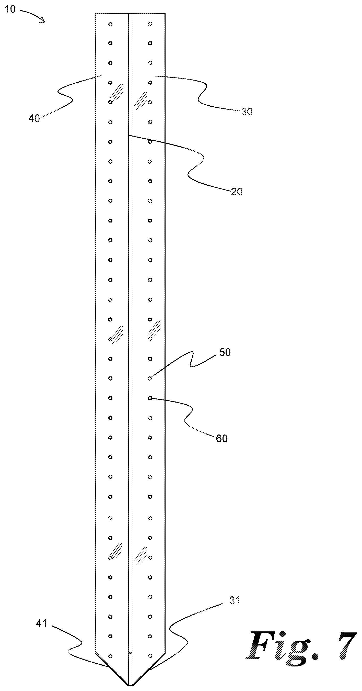
[0024] FIG. 7 is a back side elevation view of a utility post in accordance with an embodiment of the present invention;
[0025] FIG. 8 is a top plan view of a utility post in accordance with an embodiment of the present invention; and
[0026] FIG. 9 is a top plan view of a portion of a fence constructed with a utility post in accordance with an embodiment of the present invention.
[0027] It should be noted that the drawings discussed above and below are not to scale in all instances, but may have exaggerated dimensions in some respects to illustrate principles of the invention.
DETAILED DESCRIPTION OF THE INVENTION
[0028] Reference will now be made in detail to the presently preferred embodiments of the invention, one or more examples of which are illustrated in the drawings. Each example is provided by way of explanation of the invention, and is not meant as a limitation of the invention. For example, features illustrated or described as part of one embodiment may be used with a second embodiment to yield a third embodiment. It is intended that the present application include such modifications and variations as come within the scope and spirit of the invention. Repeat use of reference characters throughout the present specification and appended drawings is intended to represent the same or analogous features or elements of the invention.
[0029] Before any embodiments of the invention are explained in detail, it is to be understood that the invention is not limited in its application to the details of construction or to the arrangement of components set forth in the following description or illustrated in the following drawings. The invention is capable of other embodiments and of being practiced or of being carried out in various ways. Also, it is to be understood that the phraseology used herein is for the purpose of description and should not be regarded as limiting. The use of the words "including," "comprising," and "having" is meant to encompass the items listed thereafter and equivalents thereof, as well as additional items. Unless specified or limited otherwise, the terms "connected" and "carried by" are used broadly and encompass direct and indirect mountings, connections, supports, or couplings. Further, such phraseology is not limited to physical or mechanical connections or couplings.
[0030] A utility post, generally 10, is provided. Utility post 10 may include a rib 20, a first flange 30, and a second flange 40. Multiple apertures, for example apertures 50, 60, may be defined through rib 20, first flange 30, and/or second flange 40. Rib 20 may define a depth D. First flange 30 and/or second flange 40 may each define a length L.
[0031] Post 10 may be integrally formed. Alternatively, post 10 may be configured from attachment of a rib 20 to a first flange 30 and a second flange 40, for example by weldment. Still further alternatively, first flange 30 and second flange 40 may be integrally formed, or first flange 30 may be attached to second flange 40, and then attached to rib 20. Still further, post 10 may be roll formed, for example as illustrated in FIG. 8.
[0032] Post 10 may be fabricated from a single material, such as steel, aluminum, plastic, polyvinyl chloride, or laminates of various materials. Alternatively, post 10 may be fabricated from different materials, with rib 20 comprising a first material, first flange 30 comprising a second material, and second flange 40 comprising yet a third material.
[0033] Rib 20 may extend the full length of either first flange 30 or second flange 40, or both. Alternatively, rib 20 make extend only a portion of the length of first flange 30 and/or second flange 40. Still alternatively, first flange 30 may extend the full length of rib 20, or only a portion thereof. Similarly, second flange 40 may extend the full length of rib 20, or only portion thereof.
[0034] In an embodiment in which flanges 30, 40 extend the full length of rib 20, or much of the full length of rib 20, plural apertures, such as 50, 60, 70, may be included along that full length. So configured, post 10 would maximize the flexibility of use by a consumer in that an upper rail, for example A or B, may be located not necessarily at the top of post 10, but at any height as desired in a particular application. Similarly, a lower rail A, B might also be attached not necessarily at the bottom of post 10, but at some other lower location as desired. Still further, an intermediate rail A, B may also be included, at whatever location is desired by an individual installer.
[0035] Apertures 50, 60 may be spaced such that both apertures fall within the height of an installed rail. For example, if what is known as a "2.times.4" length of lumber is to be used as a rail A or B, apertures 50, 60 may be spaced closer than 31/2 inches, so as to allow at least two screws or other fasteners to be used within apertures 50, 60 in rail A, B, inasmuch as "2.times.4" lumber is actually 31/2 inches in height when used as a rail in a fence system.
[0036] In some embodiments of post 10, the lower end may be angled to allow for easier driving of the post 10 into the ground. In particular configurations, rib 20 may be cut at an angle not ninety degrees to create a lower end that may be driven into the ground more easily. Similarly, or alternatively, first flange 30 and/or second flange 40 may be cut at an angle not ninety degrees to create a lower end that may be driven into the ground more easily.
[0037] Embodiments of post 10 are illustrated in the appended figures. In FIG. 1, post 10 is illustrated as an embodiment which first flange 30 and second flange 40 reside in a single plane. Rib 20 may extend rearwardly from flanges 30, 40, and perpendicular to the plane in which flanges 30 and 40 reside. Multiple apertures, for example 50, 60, 70, are defined through first flange 30, second flange 40, and rib 20. Also in the illustrated embodiment, first flange 30, second flange 40, and rib 20 extend for the same length, although in alternative embodiments such co-extensive lengths are not required. Rib 20 may terminate at one end at rib end 21 and second flange 40 may terminate at one end at second flange end 41; in the embodiment illustrated in FIG. 1, rib end 21 and second flange end 41 are perpendicular to the length of post 10.
[0038] FIG. 2 illustrates another view of an embodiment of a post 10, from a front perspective. In the embodiment illustrated in FIG. 2, first flange 30 and second flange 40 have been integrally formed.
[0039] FIG. 3 represents a top view of a post 10. As illustrated therein, rib 20 may be understood to define a depth D. Depth D may be configured to be generally the dimension of the width of stock lumber anticipated to be used as rails in a fence utilizing a post 10. For example, what is known as a "2.times.4" is lumber in which the thickness is actually about 11/2 inches. If a post 10 were configured for use with rails comprising "2.times.4" lumber, depth D would be generally about 11/2 inches, or less. So configured, vertical pickets could be attached to rails, for example A, B, on both sides of a fence utilizing a post 10 with "2.times.4" rails A, B, including post 10. Alternatively, for fencing in which rails were contemplated to be, for example, what is known as "1.times.6" lumber, depth D would be dimensioned at 3/4 of an inch or less, as "1.times.6" lumber is actually 3/4 inch in width. So configured, the fencing system will allow vertical pickets to be attached on both sides of rails A, B, in a uniform, uninterrupted configuration, including at post 10.
[0040] Also as illustrated in FIG. 3, first flange 30 and second flange 40 may be understood to define a length L. Owing to the versatility of post 10, length L may be configured according to actual dimensions of nominally sized lumber. For example, if a post 10 were to be used with nominal "2.times.4" lumber, length L may be dimensioned to be 11/2 inches or less. Alternatively, if post 10 were anticipated to be used with nominal "1.times.6" lumber, length L may be dimension to be 3/4 inch or less, inasmuch as such lumber is actually 3/4 inch in thickness rather than one inch in thickness. So configured, and as illustrated in FIG. 4, post 10 would thereby allow use of post 10 not only as a post along a linear expanse of fencing, but also as a corner post. As illustrated in FIG. 4, post 10 is used as a corner post. Rail A is installed at post 10 from a first direction, and rail B is installed at post 10 in a second direction that is perpendicular to the first direction of the rail A.
[0041] FIGS. 5, 6, 7, and 8 illustrate other views of exemplary embodiments of a post 10, depicting first flange 30, second flange 40, and rib 20. In the embodiment illustrated in FIG. 6, rib end 21 and second flange end 41 have been angled to allow for easier driving of the post 10 into the ground, at an angle not ninety degrees to create a lower end that may be driven into the ground more easily.
[0042] Similarly, in the embodiment illustrated in FIG. 7, rib end 21, first flange end 31, and second flange end 41 have been angled to allow for easier driving of the post 10 into the ground, at angles not ninety degrees to create lower ends that may be driven into the ground more easily.
[0043] FIG. 8 illustrates a utility post 10 integrally formed, by roll forming. Apertures 50, 60, and 70 are defined through first flange 30, second flange 40, and rib 20, respectively. A single piece of stock may be folded at first fold 81, second fold 82, and third fold 83 to provide a configuration according to the present invention. Apertures 50, 60, and 70 may be defined through the firs flange 30, the second flange 40 and the rib 20, respectively.
[0044] FIG. 9 is a top plan view of a portion of a fence constructed with a utility post in accordance with an embodiment of the present invention. As illustrated, first rail A and second rail B are attached to post 10 perpendicular to one another. Pickets P1-P8 are attached to first rail A and second rail B, by use of fasteners, such as screws or nails, F1-F14. More specifically, pickets P1 and P2 are attached to a first side of first rail A, and pickets P7 and P8 are attached to the opposite side of first rail A; pickets P3 and P4 are attached to a first side of second rail B and pickets P5 and P6 are attached to the opposite side of second rail B.
[0045] So configured, a post 10 may first be installed in the ground, extending vertically upward. A first rail A may be attached to first flange 30, for example by fasteners such as screws or nails through apertures 50, 60. A second rail B may be attached to second flange 40, in similar fashion. Vertical pickets, for example P1-P8, may then be attached to rails A, B, including at post 10 because of the advantageous sizing of depth D and/or length L.
[0046] It should be appreciated that, in the above description of embodiments, various features are sometimes grouped together in a single embodiment, figure, or description for the purpose of streamlining the disclosure and aiding in the understanding of one or more of the various inventive aspects. This method of disclosure, however, is not be interpreted as reflecting an intention that any claim requires more features than are expressly recited in that claim. Moreover, any components, features, or steps illustrated and/or described in a particular embodiment herein, can be applied to or used with any other embodiment. Thus, it is intended that the scope of the inventions herein disclosed should not be limited by the particular embodiments described above, but should be determined only by a fair reading of the claim that follows.
* * * * *
D00000
D00001
D00002
D00003
D00004
D00005
D00006
D00007
D00008
D00009
XML
uspto.report is an independent third-party trademark research tool that is not affiliated, endorsed, or sponsored by the United States Patent and Trademark Office (USPTO) or any other governmental organization. The information provided by uspto.report is based on publicly available data at the time of writing and is intended for informational purposes only.
While we strive to provide accurate and up-to-date information, we do not guarantee the accuracy, completeness, reliability, or suitability of the information displayed on this site. The use of this site is at your own risk. Any reliance you place on such information is therefore strictly at your own risk.
All official trademark data, including owner information, should be verified by visiting the official USPTO website at www.uspto.gov. This site is not intended to replace professional legal advice and should not be used as a substitute for consulting with a legal professional who is knowledgeable about trademark law.