Sanitary Drum Fitting And Method Of Installing Same
Baughman; Gary
U.S. patent application number 16/414994 was filed with the patent office on 2019-11-21 for sanitary drum fitting and method of installing same. The applicant listed for this patent is Rieke Corporation. Invention is credited to Gary Baughman.
| Application Number | 20190352057 16/414994 |
| Document ID | / |
| Family ID | 68532747 |
| Filed Date | 2019-11-21 |
| United States Patent Application | 20190352057 |
| Kind Code | A1 |
| Baughman; Gary | November 21, 2019 |
SANITARY DRUM FITTING AND METHOD OF INSTALLING SAME
Abstract
A closure for drums and containers accommodating sanitary fittings is contemplated. The closure is attached in a manner that avoids any recesses along the interior of the contain
| Inventors: | Baughman; Gary; (Fort Wayne, IN) | ||||||||||
| Applicant: |
|
||||||||||
|---|---|---|---|---|---|---|---|---|---|---|---|
| Family ID: | 68532747 | ||||||||||
| Appl. No.: | 16/414994 | ||||||||||
| Filed: | May 17, 2019 |
Related U.S. Patent Documents
| Application Number | Filing Date | Patent Number | ||
|---|---|---|---|---|
| 62672683 | May 17, 2018 | |||
| Current U.S. Class: | 1/1 |
| Current CPC Class: | B65D 7/40 20130101; B21D 51/42 20130101; B65D 39/00 20130101; B65D 39/084 20130101 |
| International Class: | B65D 39/08 20060101 B65D039/08 |
Claims
1. A sanitary closure bushing received in an aperture of a container, the bushing comprising: a hollow cylinder having sidewalls along a top portion and a lower portion; a flange extending radially outward from a terminal edge of the top portion; wherein an annular transition is as created as a thickness of the sidewall in the top portion is reduced to a lesser thickness of the sidewall in the lower portion; and wherein an outer diameter of the annular transition seals to an inner diameter of the aperture in the container.
2. The bushing of claim 1 further comprising a collar positioned circumferentially around an outer surface of the sidewall in the lower portion.
3. The bushing of claim 2 wherein the sidewall of the lower portion is at least partially curled around the collar.
4. The bushing of claim 3 wherein the annular transition and one of the gasket and the curled sidewall cooperate to secure the bushing to the container.
5. The bushing of claim 4 wherein the curled sidewall completely captures the collar between the curled sidewall and the container.
6. The bushing of claim 4 wherein the collar is a resilient gasket.
7. The bushing of claim 4 where the container includes at least one angled wall portion immediately proximate to the aperture.
8. The bushing of claim 4 wherein the flange includes an annular groove to receive a sanitary sealing member.
9. The bushing of claim 4 wherein the hollow cylinder includes a threaded portion along an inner facing.
10. The bushing of claim 9 further comprising a threaded plug engaging the threaded portion.
11. The bushing of claim 10 wherein the threaded plug captures a sealing member between the threaded plug and the flange when the threaded plug is screwed at least partially into the hollow cylinder.
12. A method of creating a sanitary fitting in a container comprising: creating an aperture in a container; positioning a tubular bushing a shoulder transitioning a thicker sidewall end to a thinner sidewall end so that the thinner sidewall end extends into the container and the thicker sidewall end protrudes out of the container; and curling a terminal edge of the thinner sidewall end outwardly around a collar fitted an exterior circumference of the tubular bushing until the curled sidewall secures the tubular bushing by capturing an edge of the container proximate to the aperture between the shoulder and at least one of the collar and the curled terminal edge.
13. The method of claim 12 wherein the collar comprises a resilient gasket.
14. The method of claim 12 wherein the curled terminal edge of the thinner sidewall completely encases the collar.
15. The method of claim 12 wherein a sanitary fitting is provided on a radial flange positioned proximate to the thicker sidewall end.
16. The method of claim 12 wherein a thread is formed on an inner diameter of the tubular bushing.
17. The method of claim 12 wherein the creating the aperture and the curling the terminal edge occur simultaneously.
Description
CROSS REFERENCE TO RELATED APPLICATIONS
[0001] This application claims priority to U.S. Provisional Patent Application Ser. No. 62/672,683, filed on May 17, 2018. It is incorporated by reference in its entirety herein.
FIELD OF INVENTION
[0002] The following disclosure and invention relate to drum closures and, more particularly, to a drum fitting that presents a sanitary head fitting on the exterior and, along the interior, avoids creating any gaps or cavities where fluid could be entrapped, as well as method for installing the same.
BACKGROUND
[0003] For decades large scale containers, such as drums and other industrial vessels, have proven useful for storing and transporting all manner of fluids. A key point of utility in these type of containers is their ability to create accommodate openings with removable closures. These closures enable users to selectively fill and withdraw fluids from the container in a reliable, cost-effective, and secure manner.
[0004] Consequently, a variety of tools have been developed to create apertures in the sidewall of a drum or container and then secure a fitting within the aperture that receives and engages a closure. Examples of such a closure and fitting can be found in U.S. Pat. Nos. 7,168,585 and 7,690,526. A method and tool for such closures and fittings can be found in U.S. Pat. No. 7,591,054. These patents are all incorporated by reference herein.
[0005] Generally speaking, in these conventional methods, cylindrical fittings are inserted into apertures formed in the container sidewall. The aperture and corresponding shape of the cylinder may be circular, although use of a hexagonal shape can prevent unwanted torque and twisting of the fitting as the closure is rotated in and out of place.
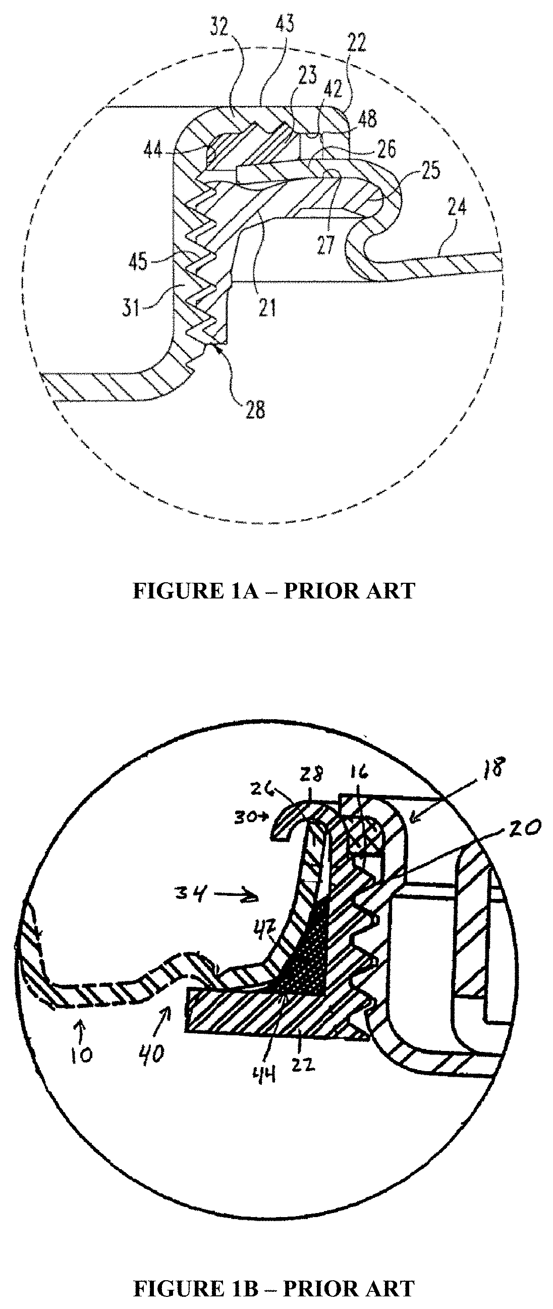
[0006] In FIG. 1A, a threaded bushing 21 includes a peripheral flange 25. The container sidewall 24 is crimped around bushing edge 25 to create sealing surface 27. Threads 28 on the bushing 21 cooperate with threads 45 formed on a sidewall 31 of plug 22 to seal the closure. A gasket 23 is captured near the gap 44 between the plug 22 and the terminal edge 26 of the wall 24. An axial flange 48 may extend down toward the container , while grooves formed on the inner/downward facing surface 42 of plug flange 32 capture the gasket 23.
[0007] In FIG. 1B, an opening in container wall 10 is sealed by plug 18 and a polygonal-shaped bushing 30 combination. The terminal edge 26 of wall 10 is bent upward in region 34 to engage a bushing 30, while crimped and beaded end 28 of the bushing 30 holds it in place. A gasket 44 is captured between a radial flange 22 of the bushing 30 and an upturned portion 42 of the wall 10. Cooperating threads 16, 20 on the bushing 30 and plug 18 allow the plug 18 to be inserted and removed from the annular opening in the bushing 22.
[0008] Closures and associated fittings intended for use with perishable fluids present additional challenges. In particular, for gravity-feed systems (where the closure is positioned on a bottom or downward facing of the container), it is important to eliminate inner-facing recesses or gaps where fluids can become entrapped for extended periods of time. Thus, the crimp region immediately adjacent to the flange 25 of FIG. 1A and the gap denoted by reference numeral 40 in FIG. 1B cause problems in this regard.
[0009] In addition, sanitary fittings incorporate specialized features to allow for easy-to-clean, quick-to-install connections. Generally speaking, these fittings are made from stainless steel or chemically inert plastic components which can tolerate high temperatures. Separately, sanitary fittings also also tend to avoid or minimize the use of threads and grooves on inner surfaces and connection points.
[0010] In view of the foregoing, an easy to install closure that accommodates sanitary fittings for large and/or industrial sized containers would be welcomed.
SUMMARY
[0011] A sanitary fitting and closure are contemplated, as well as a method for installing the same into the sidewall of a container or drum. The closure includes a cylindrical bushing having two distinct wall thicknesses along its longitudinal axis--a thicker portion which remains on an exterior facing of the container and incorporate typical sanitary fitting features (e.g., a terminal flange capable of accommodating a connection gasket) and a thinner portion that extends into the interior of the container. A gasket is fitted along this interior facing, and appropriately sized tooling rolls the edge of the thinner portion around the gasket and into a secure, sealed connection on the inner facing of the container at the fitting opening. In turn, the fitting opening of the container is sized and shaped to accommodate the closure.
[0012] A method of installing this fitting is also contemplated. Here, an exterior tool has a cup-shape to receive the thicker portion of the fitting along the exterior of the container sidewall. The inner surface of the cup includes a groove to receive and secure the terminal flange. Separately, an interior tool presents with a stepped, cylindrical surface. The inner most cylinder fits within the inner diameter of the closure fitting. A curve transition along the interior tool is designed to curl or bead the thinner portion outward and around a gasket or collar positioned proximate to the terminal edge of the thinner portion. Thus, as the exterior and interior tools are urged toward one another, the thinner portion of the closure is beaded around the gasket and, ultimately, causes the bead to come into secure contact with the sidewall of the container. The tooling is then removed, and the container and closure may put into service.
[0013] Specific reference is made to the appended claims, drawings, and description below, all of which disclose elements of the invention. While specific embodiments are identified, it will be understood that elements from one described aspect may be combined with those from a separately identified aspect. In the same manner, a person of ordinary skill will have the requisite understanding of common processes, components, and methods, and this description is intended to encompass and disclose such common aspects even if they are not expressly identified herein.
BRIEF DESCRIPTION OF THE DRAWINGS
[0014] Operation of the invention may be better understood by reference to the detailed description taken in connection with the following illustrations. These appended drawings form part of this specification, and any information on/in the drawings is both literally encompassed (i.e., the actual stated values) and relatively encompassed (e.g., ratios for respective dimensions of parts). In the same manner, the relative positioning and relationship of the components as shown in these drawings, as well as their function, shape, dimensions, and appearance, may all further inform certain aspects of the invention as if fully rewritten herein. Unless otherwise stated, all dimensions in the drawings are with reference to inches, and any printed information on/in the drawings form part of this written disclosure.
[0015] In the drawings and attachments, all of which are incorporated as part of this disclosure, directional axis x, y, and z in the various Figures indicate the orientation for the views illustrated with FIGS. 2A, 2B, 3A, 3B, and 4A. These drawings include the following:
[0016] FIGS. 1A and 1B are sectional side views illustrating various attachments of annular closure fitting and gasket combinations to a container sidewall according to the prior art.
[0017] FIG. 2A shows a cross sectional side view of the closure according to certain aspects of the invention, while FIG. 2B is top view of the closure from FIG. 2A, with the broken lines indicating the positioning of structures (i.e., relative wall thickness, etc.) not immediately visible in this top view. FIG. 2A is taken along the y-axis, and FIG. 2B is taken along the z-axis.
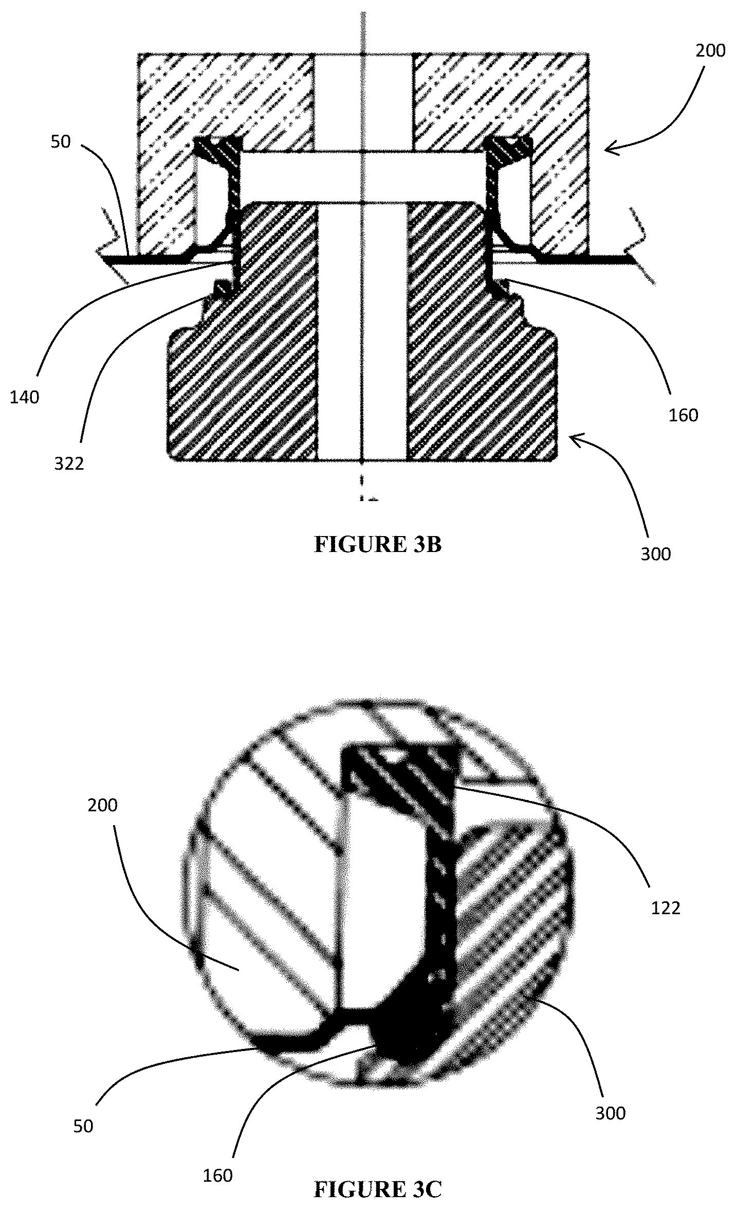
[0018] FIGS. 3A and 3B show the orientation of the closure along the y-axis as in FIG. 2A, container sidewall and tooling prior to and during installation of the closure fitting, while FIG. 3C is an exploded, sectional view of the tooling inducing the desired beading of the closure around the gasket on the interior surface of the container sidewall.
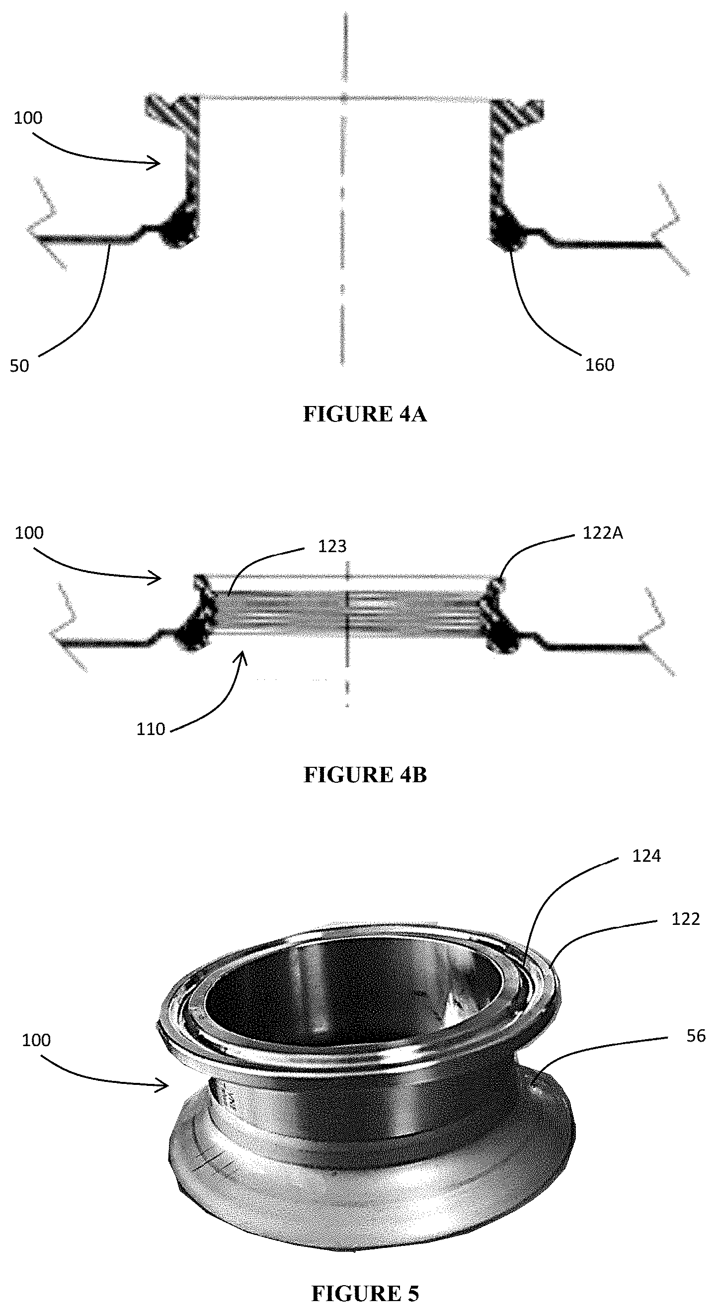
[0019] FIG. 4A is a cross sectional side view of the closure of FIG. 3A after it has been installed, while FIG. 4B shows a similar cross sectional side view but with an alternative embodiment having an interior threaded surface to receive a corresponding plug.
[0020] FIG. 5 is a three dimensional illustration of the exterior closure of FIG. 3A (i.e., the sanitary fitting that remains exposed on the exterior of the container).
DETAILED DESCRIPTION
[0021] Reference will now be made in detail to exemplary embodiments of the present invention, examples of which are illustrated in the accompanying drawings. It is to be understood that other embodiments may be utilized and structural and functional changes may be made without departing from the respective scope of the invention. As such, the following description is presented by way of illustration only and should not limit in any way the various alternatives and modifications that may be made to the illustrated embodiments and still be within the spirit and scope of the invention.
[0022] As used herein, the words "example" and "exemplary" mean an instance, or illustration. The words "example" or "exemplary" do not indicate a key or preferred aspect or embodiment. The word "or" is intended to be inclusive rather an exclusive, unless context suggests otherwise. As an example, the phrase "A employs B or C," includes any inclusive permutation (e.g., A employs B; A employs C; or A employs both B and C). As another matter, the articles "a" and "an" are generally intended to mean "one or more" unless context suggest otherwise.
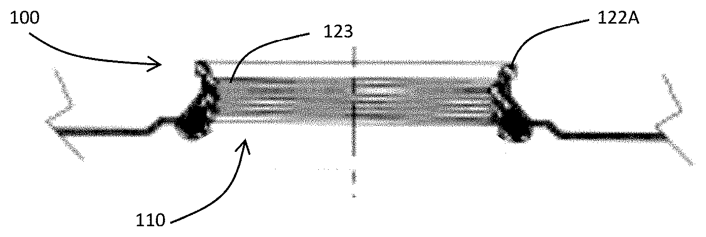
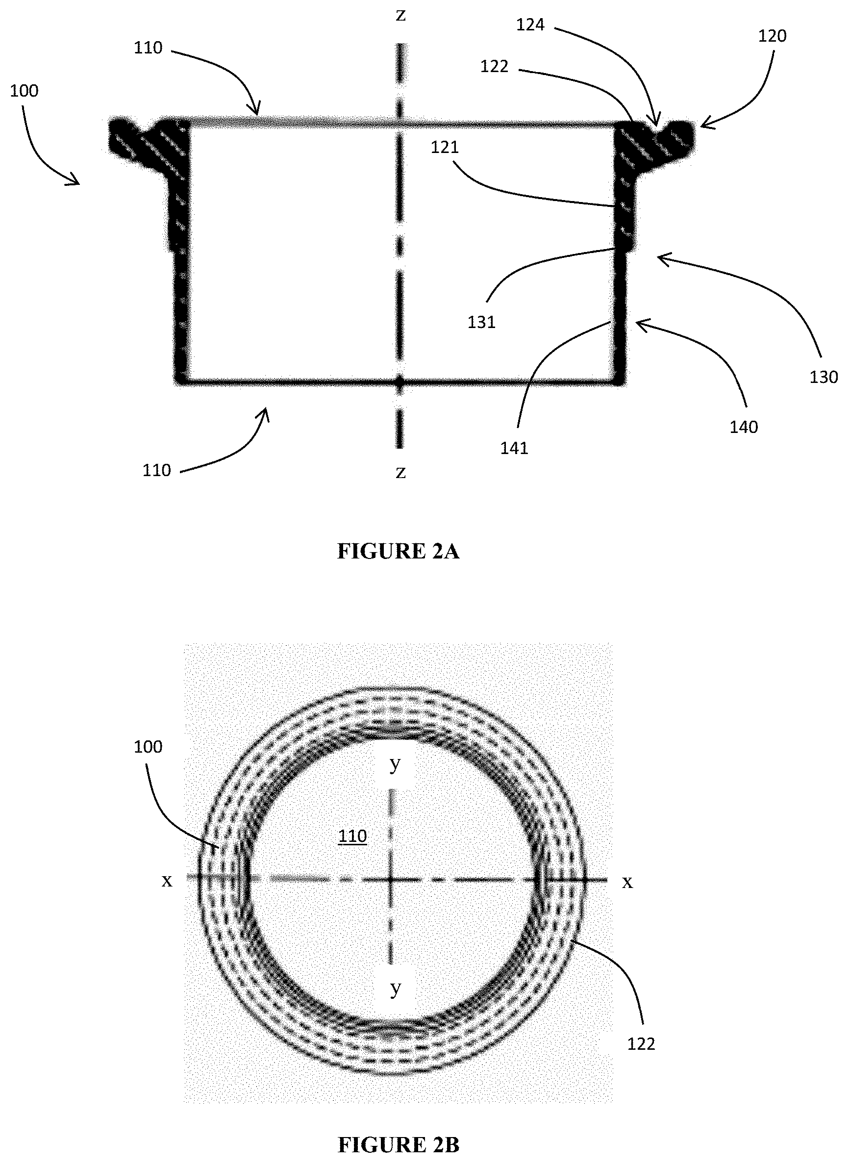
[0023] With reference to FIGS. 2A and 2B, a tubular bushing 100 is formed as a hollow cylinder. Bushing 100 includes a sanitary fitting end 120 at one end and a thinned portion end 140 at the other. The bushing 100 may be a circular cylinder along its entire inner and outer facings, preferably having the same diameter. However, it may be possible for the exterior shape of bushing 100 to differ from the interior shape defining the fluid exit of the bushing 100, particularly in its sanitary fitting end 120, as described below.
[0024] Sanitary fitting end 120 is formed at one end of the bushing 100 proximate to opening or aperture 110, oriented in a substantially straight line along the z-axis. It includes longitudinally extending sidewalls 121 and a terminal flange 122 that extends radially outward. One or more annular grooves 124 are formed in the outer facing of the flange 122. The groove can accommodate an optional gasket or sealing member (not shown), while the flange 122 is sized to allow for an annular clamp to attach the fitting end 120 to some other component, hose, or connector (not shown). As such, sanitary fitting end 120 is positioned to be on the exterior of the container, drum, or vessel after the bushing is installed as contemplated herein.
[0025] The sidewalls 121 preferably have a consistent thickness along the entire length of the sanitary fitting portion. A distinct transition 130 where the sanitary fitting end 120 connects to the thinner portion end 140.
[0026] Thinned portion end 140 is also a hollowed cylinder, preferably of the same inner diameter as the sanitary fitting portion 120. However, the sidewalls 141 of the thinner potion 140 are of lesser thickness in comparison to sanitary fitting portion 120. In effect, this creates a narrowing step 131 on the outer surface of bushing 100.
[0027] An aperture having the same shape as bushing 100 is formed in container sidewall 50. For the sake of simplicity in manufacture and use, a circular shape is preferred. The inner diameter of an aperture formed in sidewall 50 cooperates with and corresponds to the outer diameter of the thinned portion 140. In this manner, when bushing 100 is inserted and forced down into the sidewall aperture, the transition 130 engages and seals the sidewall 50 .
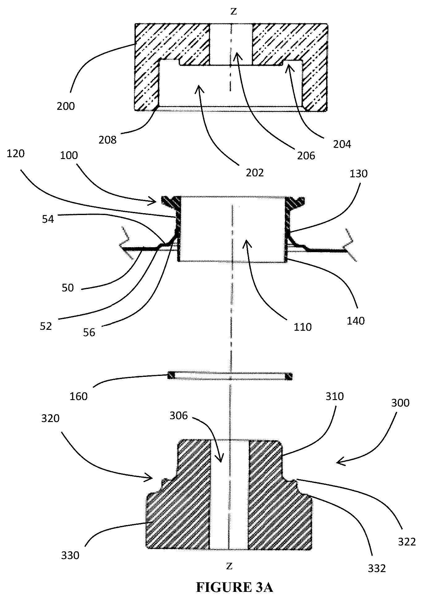
[0028] An exterior, holding tool 200 is employed to attach the bushing 100 to the container. The tool 200 has a recessed portion 202 that receives the sanitary fitting end 120. A groove may be formed in the floor 204 of the tool 200 to receive and restrain the flange 122, while the diameter of the cylindrical recess 202 is sufficient to receive the entirety of the sanitary fitting end 120. In this regard, the tool itself 200 has an overall cup shape, although an aperture 206 may be provided along the central axis to simplify alignment and/or removal of the tool 200. Beveled edge 208 guides and facilitates insertion of the bushing 100 into the tool 200 and, in conjunction with protrusion 322, shoulder 332, and the final thickness of sidewall 50, facilitates the capture of bushing 100 (including gasket 160) onto sidewall 50.
[0029] A corresponding interior tool 300 is formed as a cylinder of increasing diameter. The narrowest diameter portion 310 is along its top portion where it is inserted into the hollowed portion of the thinner portion 140 of the bushing 100. As with tool 200, an aperture 306 may be provided along the central axis, preferably having the same diameter as the aperture formed in tool 200. A collar or gasket 160 is interposed between the tool 300 and the bushing 100.
[0030] A curving transition 320 is formed to curl the sidewalls 141 outward and around the gasket 160. To encourage this formation, a curved gap is formed between narrow portion 310 and an upturned annular protrusion 322.
[0031] A larger diameter portion 330 (relative to portion 310) extends further down tool 300 beneath the protrusion 322 so as to form a shoulder 332. Shoulder 332 may engage sidewall 50 during the process of sealing bushing 100 to sidewall 50. In some embodiments, an alignment rod may pass through apertures 206, 306, 110 to keep all components in proper position as the tools are urged toward one another, as will be described in greater detail below.
[0032] Gasket 160 may be of any suitable material. Preferably, gasket 160 comes into contact with the curled or beaded sidewalls 141 on one facing and with the container sidewall 50 on the opposite facing. As such, the gasket 160 can be made of sufficiently resilient material, having flexibility and tolerance to expand and contract. In other embodiments, gasket 160 may act more like a collar that facilitates and guides the curling of sidewalls 141 during installation of the bushing 100, in which case gasket/collar 160 is partially or completely encased by the curling edge of wall 141.
[0033] Tools 200 and 300 are urged toward each other until sidewalls 141 curl and secure the bushing 100 into sealed contact with container sidewall 50, as seen in the comparative progression of FIGS. 3A, 3B, and 4A. Notably, sanitary fitting end 120 protrudes out along the exterior of the container, so as to allow for any manner of quick-connect or other sanitary-style system to be employed. Equally important, the curled sidewall 141 is urged into contact with container 50 so as to avoid any gaps or recesses in which fluids might become entrapped, as seen in FIG. 3C.
[0034] While bushing 100 is envisioned as having a smooth interior surface as seen in FIG. 4A, threads 123 may be formed on an inner side wall to the bushing 100 (i.e., along some or all of the inner facing of aperture 110), as shown in FIG. 4B. All other aspects of the construction and method of insertion/coupling of the bushing 100 to sidewall 50 is the same as described above.
[0035] The arrangement of FIG. 4B allows for the use of threaded plug, including an optional exterior grip. In this instance, a second sealing gasket could be fitted around, within, or over the narrowed flange 122A (and/or onto the threaded plug, not shown). Use of threads allows for selective sealing of the container by way of a screw attachment.
[0036] In order to secure the bushing 100 in place, welding, adhesives, and/or fasteners could be employed. Additionally or alternatively, the aperture and corresponding shape of the tubular bushing (either within the tubular form and/or as a flange or imprint provide along the interface where contact is expected and maintained between the bushing and the container) includes a polygonal shape (e.g., pentagonal, hexagonal, etc.) that prevents unwanted torque and twisting.
[0037] Aperture in container 50 can be formed to create an outward protruding cone (i.e., the exterior of the container, rather than projecting into its inner volume). In this manner, it becomes easier to engage transition portion 130. In particular, angled wall 52 forms the outer most edge that secures bushing 100 initially. A lateral annular panel 54 connects first angled wall 52 to a second angled wall 56. Each of the angled walls 52, 56 effectively form frusto-conical structures nested within one another. The angled wall 52 is of sufficient length to accommodate the curled sidewall 141 when the bushing 100 is attached via tools 200, 300. In this manner, no gap or recess is created between bushing 100 and panel 54. If present, the second angled wall 56 ensures fluid can still flow toward the opening/exit created by bushing 100.
[0038] During the insertion and capture of gasket 160, tools 200, 300 are urged together a sufficient distance to engage the curled end of wall 141 against the inner facing of sidewall 50. On the opposing, outer facing of sidewall 50, the transition step 131 engages and secures the edge of the aperture formed immediately proximate to angled wall 56. In this manner, the bushing 100 is secured in place, although additional measures may be taken to provide an even more secure fit.
[0039] The process for forming and providing a sanitary fitting to a container described above may include steps that occur sequentially or simultaneously. In particular, after providing an appropriate bushing, an aperture is formed in a panel or sidewall of the container. The bushing is then inserted, with the sanitary fitting on an exterior/out facing of the container, so that the shoulder abuts and seals to the edges of the aperture. A collar or gasket is fitted around the bushing on the interior/inner facing of the container, and the thinned wall portion is curled partly or completely around the collar/gasket. In this manner, the collar/gasket is captured and seals the inner facing, while the shoulder seals to the outer facing. The tooling described above may be used, and a commonly aligned aperture in the tooling allows for the tooling pieces and components to be aligned appropriately.
[0040] The bushing 100 is preferably made from stainless steel, although other materials common to sanitary fittings can be used. In the same manner, tools 200, 300 are made of materials of sufficient strength and tolerance to wear.
[0041] Although the embodiments of the present invention have been illustrated in the accompanying drawings and described in the foregoing detailed description, it is to be understood that the present invention is not to be limited to just the embodiments disclosed, but that the invention described herein is capable of numerous rearrangements, modifications and substitutions without departing from the scope of the claims hereafter. The features of each embodiment described and shown herein may be combined with the features of the other embodiments described herein. The claims as follows are intended to include all modifications and alterations insofar as they come within the scope of the claims or the equivalent thereof.
* * * * *
D00000
D00001
D00002
D00003
D00004
D00005
XML
uspto.report is an independent third-party trademark research tool that is not affiliated, endorsed, or sponsored by the United States Patent and Trademark Office (USPTO) or any other governmental organization. The information provided by uspto.report is based on publicly available data at the time of writing and is intended for informational purposes only.
While we strive to provide accurate and up-to-date information, we do not guarantee the accuracy, completeness, reliability, or suitability of the information displayed on this site. The use of this site is at your own risk. Any reliance you place on such information is therefore strictly at your own risk.
All official trademark data, including owner information, should be verified by visiting the official USPTO website at www.uspto.gov. This site is not intended to replace professional legal advice and should not be used as a substitute for consulting with a legal professional who is knowledgeable about trademark law.