Stackable Containers And Methods Of Making The Same
Pohlman; Christopher John ; et al.
U.S. patent application number 15/985324 was filed with the patent office on 2019-11-21 for stackable containers and methods of making the same. The applicant listed for this patent is Inline Plastics Corp.. Invention is credited to Carrie Cline, Christopher John Pohlman.
| Application Number | 20190352046 15/985324 |
| Document ID | / |
| Family ID | 68532731 |
| Filed Date | 2019-11-21 |


| United States Patent Application | 20190352046 |
| Kind Code | A1 |
| Pohlman; Christopher John ; et al. | November 21, 2019 |
STACKABLE CONTAINERS AND METHODS OF MAKING THE SAME
Abstract
A container includes a first container portion and a second container portion. The first container portion includes a first panel and a first sidewall extending from the first panel. The first panel includes a groove formed around at least a portion of a perimeter of the first panel. The second container portion includes a second panel and a second sidewall extending from the second panel toward the first container portion when the container is in a closed position. The second panel includes an outwardly projecting rib formed around at least a portion of a perimeter of the second panel.
| Inventors: | Pohlman; Christopher John; (West Haven, CT) ; Cline; Carrie; (Milford, CT) | ||||||||||
| Applicant: |
|
||||||||||
|---|---|---|---|---|---|---|---|---|---|---|---|
| Family ID: | 68532731 | ||||||||||
| Appl. No.: | 15/985324 | ||||||||||
| Filed: | May 21, 2018 |
| Current U.S. Class: | 1/1 |
| Current CPC Class: | B65D 21/0202 20130101; B65D 43/021 20130101; B65D 21/022 20130101; B65D 85/36 20130101; B65D 2543/00296 20130101; B65D 2401/10 20200501; B65D 2543/00194 20130101; B65D 2401/05 20200501; B65D 2543/00351 20130101; A47G 21/001 20130101; B65D 2203/02 20130101; B65D 2401/25 20200501 |
| International Class: | B65D 21/02 20060101 B65D021/02; B65D 43/02 20060101 B65D043/02 |
Claims
1. A container comprising: a first container portion including a first panel and a first sidewall extending from the first panel, wherein the first panel includes a groove formed around at least a portion of a perimeter of the first panel; and a second container portion including a second panel and a second sidewall extending from the second panel toward the first container portion when the container is in a closed position, wherein the second panel includes an outwardly projecting rib formed around at least a portion of a perimeter of the second panel.
2. The container as recited in claim 1, wherein the groove is u-shaped.
3. The container as recited in claim 1, wherein the outwardly projecting rib is u-shaped.
4. The container as recited in claim 1, wherein the groove of the first panel is configured and adapted to mate with an outwardly projecting rib of another container.
5. The container as recited in claim 1, further comprising a gradual curved transition portion between the first panel and the first sidewall.
6. The container as recited in claim 1, wherein the first panel includes a plateau portion raised with respect to the groove, wherein the plateau portion defines an outwardly facing surface.
7. The container as recited in claim 1, wherein the groove includes two linear segments.
8. The container as recited in claim 7, wherein the groove includes a third linear segment connecting the two linear segments.
9. The container as recited in claim 8, wherein the groove includes two arcuate transitions, wherein each arcuate transition is adjacent to a respective end of the third linear segment, wherein each arcuate transition connects the third linear segment to a respective end of one of the two linear segments.
10. The container as recited in claim 1, wherein the outwardly projecting rib includes two linear segments.
11. The container as recited in claim 9, wherein the outwardly projecting rib includes a third linear segment connecting the two linear segments.
12. The container as recited in claim 11, wherein the outwardly projecting rib includes two arcuate transitions, wherein each arcuate transition is adjacent to a respective end of the third linear segment, wherein each arcuate transition connects the third linear segment to a respective end of one of the two linear segments.
13. The container as recited in claim 1, wherein the first container portion is configured and adapted to engage with the second container portion to form a leak resistant seal when the container is in the closed position.
14. The container as recited in claim 1, further comprising a hinge joining the first container portion to the second container portion.
15. The container as recited in claim 14, wherein the first and second container portions and the hinge are formed from a single sheet of material.
16. The container as recited in claim 1, wherein the second container portion is a base of the container and the second panel is a bottom panel of the base, wherein the outwardly projecting rib of the bottom panel is configured and adapted to mate with a groove of another container.
17. The container as recited in claim 1, wherein the first container portion is a lid of the container and the first panel is a top panel of the lid, wherein the groove of the top panel is configured and adapted to mate with an outwardly projecting rib of another container.
18. A container assembly comprising: a container including: a lid including an upper surface and a sidewall, wherein the upper surface includes a groove formed around at least a portion of a perimeter of the upper surface; and a base having a bottom surface and a sidewall extending from the bottom surface toward the lid when the container is in a closed position, wherein the bottom surface includes a downwardly projecting rib formed around at least a portion of a perimeter of the bottom surface.
19. The container assembly as recited in claim 18, wherein the container is a first container, wherein the container assembly includes a second container, wherein the second container includes: a lid including an upper surface and a sidewall, wherein the upper surface includes a groove formed around at least a portion of a perimeter of the upper surface; and a base having a bottom surface and a sidewall extending from the bottom surface toward the lid when the second container is in a closed position, wherein the bottom surface includes a downwardly projecting rib formed around at least a portion of a perimeter of the bottom surface, wherein the second container is stacked on top of the lid of the first container, and wherein the downwardly projecting rib of the second container is nested within the groove of the first container.
20. The container assembly as recited in claim 19, wherein the first container includes a gradual curved transition portion between the upper surface and the sidewall, wherein the first container includes a label extending from the upper surface of the lid, over the gradual curved transition portion toward the base of the first container, wherein the label is in direct abutment with the upper surface of the lid of the first container to mitigate interference with the second container stacked on top of the first container.
Description
FIELD OF THE INVENTION
[0001] The present disclosure is directed to constructions and methods of making stackable containers, and more particularly to, containers that have a lid and base with interconnecting stacking features such as grooves and/or projecting ribs. The interconnecting stacking features are configured and adapted to reduce or eliminate tearing of labels when multiple containers are stacked on one another and to facilitate upright stacking of multiple containers even with a label applied.
BACKGROUND OF THE INVENTION
[0002] When a thermoplastic container or cup is covered on one side with a label, mechanisms used for stacking containers, such as rails on the top surface, tend to raise the labels above the top surface of the container, such that there is a gap between the label and the top surface of the container, also known as "tenting." As a result, when a second container is stacked upon the first, the label can be torn proximate to the area where the gap is, as there is no support behind the label. Moreover, because the label is raised with respect to the top of the container (e.g. "tented") the mating recessed portions on the bottom of the second container do not mate properly and can cause the second container to be tilted with respect to the lid of the first. This tends to present problems when many containers need to be stacked, as the angle between the first container and those progressively stacked gets larger and larger the more containers that are stacked.
[0003] The tearing results in a number of possible problems, including altering the appearance of the container to the point that consumers may not want to purchase or would otherwise return a product in a container with a torn label. Furthermore, when such containers are to be stacked on store shelves, for example, the tilting may have a negative impact on the stackability of the containers. For example, instead of a linear stack of containers, the stack can be tilted off axis and result in containers falling.
[0004] In general, the present containers have been considered satisfactory for their intended purpose. There is a need, therefore, for improved containers that are adapted and configured to reduce or eliminate label tearing when the container is stacked, or other stacking issues.
SUMMARY OF THE INVENTION
[0005] The purpose and advantages of the below described illustrated embodiments will be set forth in and apparent from the description that follows. Additional advantages of the illustrated embodiments will be realized and attained by the containers and methods particularly pointed out in the written description and the claims herein, as well as from the drawings.
[0006] To achieve these and other advantages and in accordance with the purpose of the illustrated embodiments, in one embodiment, described herein is a container having a first container portion and a second container portion. The first container portion includes a first panel and a first sidewall extending from the first panel. The first panel includes a groove formed around at least a portion of a perimeter of the first panel. The second container portion includes a second panel and a second sidewall extending from the second panel toward the first container portion when the container is in a closed position. The second panel includes an outwardly projecting rib formed around at least a portion of a perimeter of the second panel. In certain constructions, the first and second panels include substantially planar portions. Alternatively, the first and second panels can include convex/concave portions.
[0007] In embodiments of the present disclosure, the groove is u-shaped and/or the outwardly projecting rib is u-shaped. It is contemplated that the groove of the first panel is configured and adapted to mate with an outwardly projecting rib of another container. It is envisioned that, in constructions where the container is round, the first and second panels can be circular and the groove and/or outwardly projecting rib can include one or more arcuate portions. In such constructions, the first and second sidewalls have a circular cross-section and define a longitudinal axis for the container and the base has a cross section that is axially symmetrical.
[0008] It is envisioned that the first container portion can include a gradual curved transition portion between the first panel and the first sidewall. It is contemplated that the first panel can include a plateau portion raised with respect to the groove. The plateau portion can define an outwardly facing surface.
[0009] It is envisioned that in certain embodiments, the groove includes two linear segments. The two linear segments can be parallel to one another. It is contemplated that the groove can include a third linear segment connecting the two linear segments. The groove can include two arcuate transitions. Each arcuate transition can be adjacent to a respective end of the third linear segment. Each arcuate transition can connect the third linear segment to a respective end of one of the two linear segments.
[0010] In accordance with some embodiments, the outwardly projecting rib includes two linear segments. The two linear segments of the outwardly projecting rib can be parallel to one another. It is contemplated that, in certain embodiments, the outwardly projecting rib includes a third linear segment connecting the two linear segments. The outwardly projecting rib can include two arcuate transitions. Each arcuate transition can be adjacent to a respective end of the third linear segment. Each arcuate transition can connect the third linear segment to a respective end of one of the two linear segments.
[0011] In embodiments of the present disclosure, the first container portion is configured and adapted to engage with the second container portion to form a leak resistant seal when the container is in the closed position. In some embodiments, the container can include a hinge joining the first container portion to the second container portion. It is also contemplated that the container can be a two-piece container without a hinge. In accordance with some embodiments, the first and second container portions and the hinge can be formed from a single sheet of material.
[0012] In embodiments of the present disclosure, the second container portion is a base of the container, the second panel is a bottom panel of the base, and the second sidewall extends upwardly from the bottom panel. It is also contemplated that in some embodiments, the second container portion can be a lid of the container. The bottom panel can include a planar portion upwardly recessed toward the first container portion with respect to the outwardly projecting rib. It is envisioned that in accordance with some embodiments, the outwardly projecting rib of the bottom panel is configured and adapted to mate with a groove of another container, e.g. a groove on the lid of another container.
[0013] In embodiments of the present disclosure, the first container portion is a lid of the container, the first panel is a top panel of the lid, and the first sidewall extends downwardly from the top panel. It is also contemplated that in some embodiments, the first container portion can be a base of the container. It is envisioned that in accordance with some embodiments, the groove of the top panel is configured and adapted to mate with an outwardly projecting rib of another container, e.g. an outwardly projecting rib on the base of another container.
[0014] In accordance with another aspect, a container assembly includes a container having a lid and a base. The lid includes an upper surface and a sidewall. The upper surface includes a groove formed around at least a portion of a perimeter of the upper surface. The base has a bottom surface and a sidewall extending from the bottom surface toward the lid when the container is in a closed position. The bottom surface includes a downwardly projecting rib formed around at least a portion of a perimeter of the bottom surface.
[0015] In accordance with some embodiments, the container is a first container and the container assembly includes a second container. The second container can include a lid and a base. The lid of the second container is similar to lid of the first container. The base of the second container is similar to the base of the first container. The base of the second container can have a bottom surface and a sidewall extending from the bottom surface toward the lid when the second container is in a closed position. The bottom surface of the second container can include a downwardly projecting rib formed around at least a portion of a perimeter of the bottom surface. In embodiments of the present disclosure, the second container is stacked on top of the lid of the first container and the downwardly projecting rib of the second container is nested within the groove of the first container.
[0016] It is envisioned that the first container includes a gradual curved transition portion between the upper surface and the sidewall. In accordance with some embodiments, the first container includes a label extending from the upper surface of the lid, over the gradual curved transition portion toward the base of the first container. The label can be in direct abutment with the upper surface of the lid of the first container to mitigate interference with the second container stacked on top of the first container.
BRIEF DESCRIPTION OF THE DRAWINGS
[0017] So that those having ordinary skill in the art, to which the present embodiments pertain, will more readily understand how to manufacture the novel containers and employ the novel methods, certain illustrated embodiments thereof will be described in detail herein-below with reference to the drawings, wherein:
[0018] FIG. 1A is a perspective view of a container which has been constructed in accordance with an embodiment of the present disclosure showing the container in the closed position with a label applied over one side of the container;
[0019] FIG. 1B is a perspective view of the container of FIG. 1A shown in the closed position without a label;
[0020] FIG. 2 is an underside perspective view of the container of FIG. 1A shown in the open position without any label;
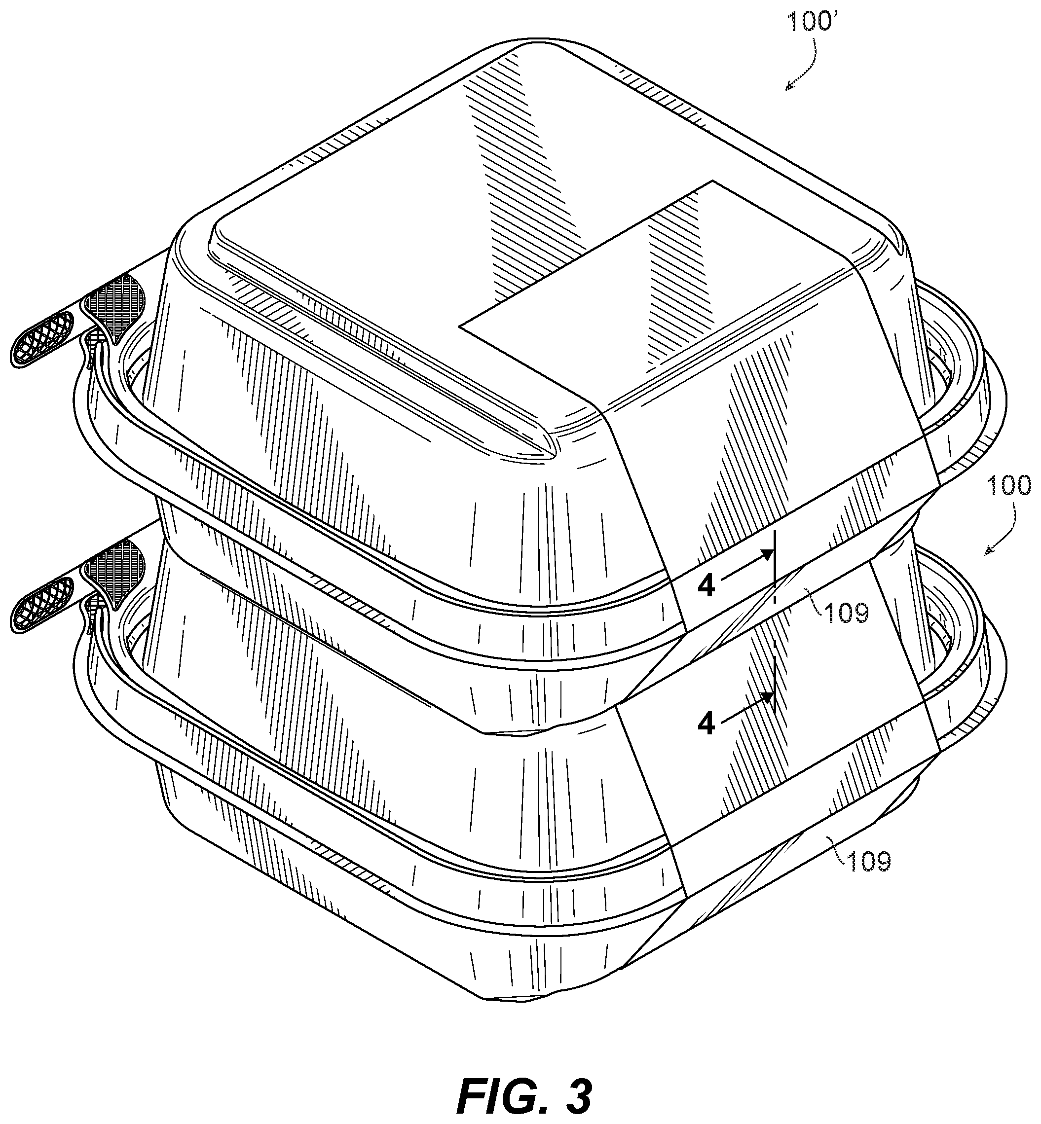
[0021] FIG. 3 is a perspective view of two containers constructed in accordance with an embodiment of the present disclosure, one of which has been stacked on top of the other; and
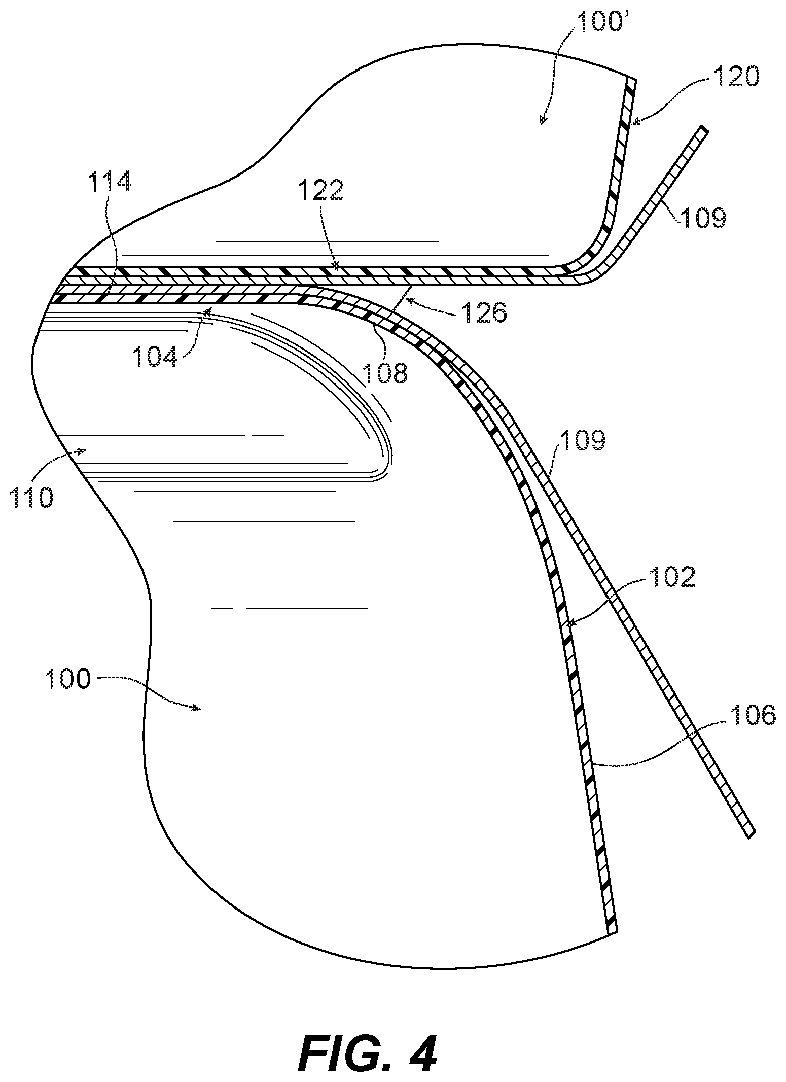
[0022] FIG. 4 is a detail view of the stacked containers of FIG. 3, showing a partial cross-sectional depiction of how the base of the top container rests on the lid of the bottom container.
DETAILED DESCRIPTION OF THE DRAWINGS
[0023] The below illustrated embodiments are directed to container constructions and methods of making the same, and more particularly to, containers that have a lid which is constructed to reduce or eliminate damage to a label on the container when the container is stacked during shipment and retail, and to ensure easier more reliable stacking of many containers. It is to be appreciated the below illustrated embodiments are not limited in any way to what is shown, as the illustrated embodiments described below are merely exemplary of the invention, which can be embodied in various forms, as appreciated by one skilled in the art. Therefore, it is to be understood that any structural and functional details disclosed herein are not to be interpreted as limiting, but merely as a basis for the claims and as a representative for teaching one skilled in the art to variously employ the certain illustrated embodiments.
[0024] Unless defined otherwise, all technical and scientific terms used herein have the same meaning as commonly understood by one of ordinary skill in the art relating to the below illustrated embodiments. Although any methods and materials similar or equivalent to those described herein can also be used in the practice or testing of the below illustrated embodiments, exemplary methods and materials are now described.
[0025] Referring now to FIGS. 1A-1B, there is illustrated a container which has been constructed in accordance with an embodiment of the present invention that has been designated as reference numeral 100. Other embodiments of containers in accordance with the disclosure, or aspects thereof, are provided in FIGS. 2-4 as will be described. Container 100 has top and bottom surfaces that are generally square shaped and includes trapezoidal shaped sidewalls. Container 100 includes rounded corners between adjoining sides/surfaces. Those skilled in the art will readily appreciated that other size and shape containers, vessels, etc. can be used without departing from the scope of the present disclosure.
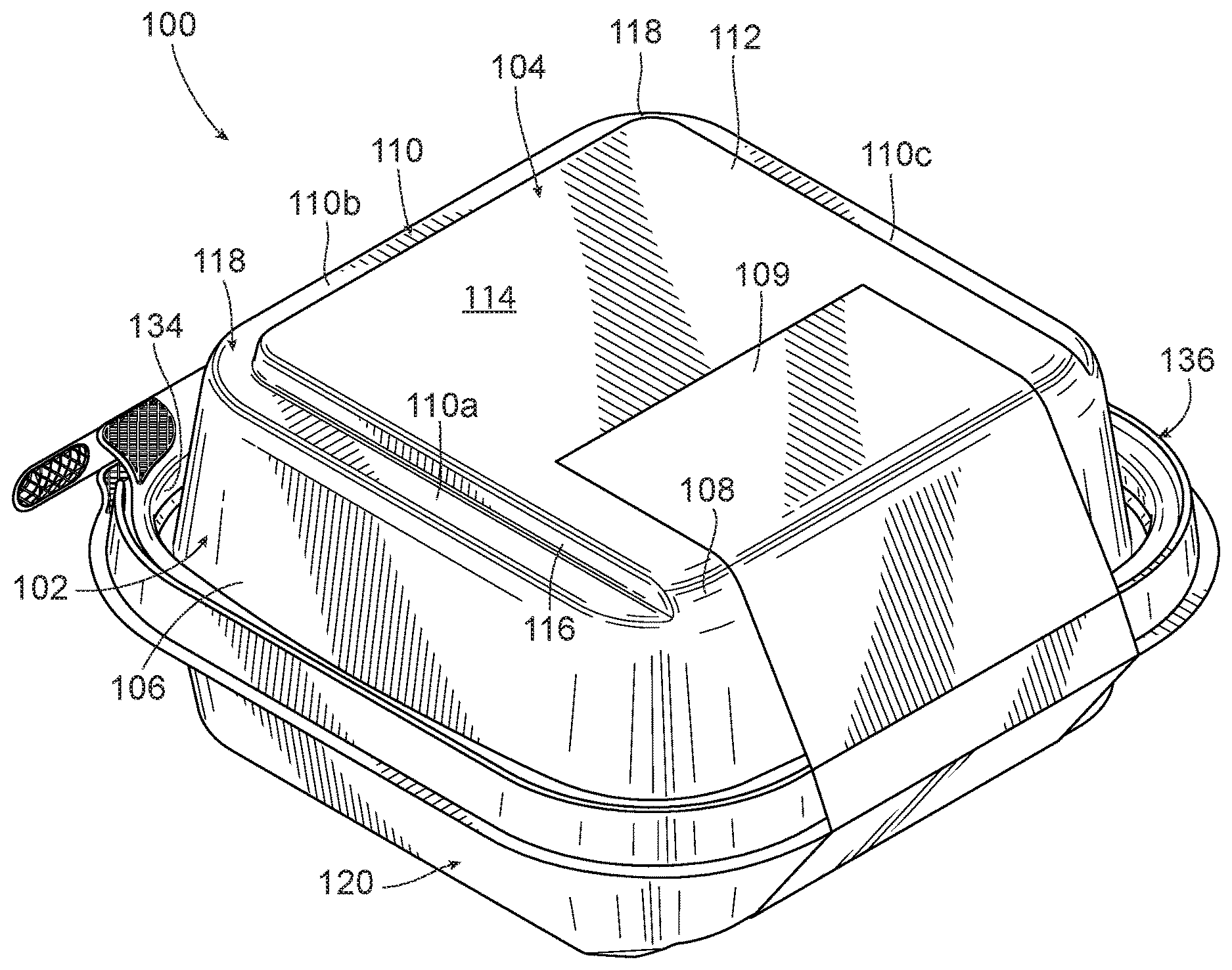
[0026] As shown in FIGS. 1A-1B, container 100 includes a first container portion, e.g. a lid 102, having a first panel, e.g. top panel 104, a first sidewall, e.g. downwardly extending sidewall 106. Top panel 104 includes a groove 110 and a flat plateau portion 112 raised with respect to groove 110. Plateau portion 112 defines an outwardly facing surface 114. Groove 110 is formed around at least a portion of a perimeter of plateau portion 112. Instead of having a groove or other indented portion (similar to groove 110) between plateau portion 112 and downwardly extending sidewall 106 around the entire perimeter of plateau portion 112, at least a portion of lid 102 between downwardly extending sidewall 106 and top panel 104 is a gradual curved transition portion 108. Gradual curved transition 108, e.g. a smooth transition surface, extends between plateau portion 112 of top panel 104 and downwardly extending sidewall 106.
[0027] In the embodiment of FIGS. 1A-1B, gradual curved transition portion 108 is between outwardly facing surface 114 of plateau portion 112 and downwardly extending side wall 106. When a label 109 is applied on lid 102, gradual curved transition 108 allows label 109 to extend from outwardly facing surface 114, over curved transition 108 and downward towards side wall 106 without a gap forming between label 109 and top panel 104 of lid 102, meaning that label 109 is supported as it extends over top panel 104, thereby avoiding or reducing tearing and damage to label 109 if another container is stacked upon top panel 104 of container 100.
[0028] In the embodiment of FIG. 1A, groove 110 includes three indented linear segments 110a, 110b and 110c, that are joined together to form a u-shape about the perimeter of plateau portion 112. Indented portions 110a-110c define a perimeter edge 116 of plateau portion 112 along three sides of plateau portion 112. Each linear segment 110a-110c is parallel to a respective side of the plateau portion. In the embodiment of FIG. 1A, linear segments 110a and 110c are parallel to one another. Arcuate transitions 118 at each end of middle linear segment 110b connect middle linear segment 110b to linear segments 110a and 110c adjacent thereto. Groove 110 facilitates stacking of another container on top of container 100, described in more detail below with reference to FIG. 3. Because groove 110 is not defined around the entire perimeter of top panel 104, a portion (e.g. the fourth side in this case) is left available for the gradual curved transition portion 108, described above. It is also contemplated that, in some embodiments, groove 110 could be defined on less than three sides of container 100, groove 110 could be formed from three discrete linear segments not connected by arcuate portions, and/or that groove 110 could be an indented portion formed in another location on top panel 104. For example, groove 110 could include a series of indents located in a variety of positions across top panel 104.
[0029] With reference now to FIG. 2, container 100 includes a second container portion, e.g. a base 120, that is configured and adapted to engage with lid 102 to form a leak resistant seal when container 100 is closed. Base 120 includes a second panel, e.g. a bottom panel 122, and a second sidewall, e.g. an upwardly extending sidewall 124, connected to the bottom panel 122. As shown in FIG. 1A, downwardly extending sidewall 106 of lid 102 is surrounded by a peripheral sealing surface (not shown) proximate to an upwardly extending flange 134 on lid 102. Upwardly extending sidewall 124 of base 120 includes an upper peripheral rim 136 and a sealing surface (not shown) which engages with the peripheral sealing surface associated with lid 102 to form a leak resistant seal.
[0030] As shown in FIG. 2, bottom panel 122 includes an outwardly projecting rib 126 and a planar portion 128. Planar portion 128 is upwardly recessed toward the lid 102 with respect to the outwardly projecting rib 126. The outwardly projecting rib 126 is formed around at least a portion of a perimeter of bottom panel 122. Outwardly projecting rib 126 includes three linear segments 126a-126c that are joined together to form a u-shape. In the embodiment of FIG. 2, linear segments 126a and 126c are parallel to one another. Linear segments 126a-126c are joined together with arcuate transitions 132.
[0031] As shown in FIGS. 2-4, the u-shape formed in-part by raised linear segments 126a-126c is configured to mate with a corresponding u-shape (e.g. that formed by linear segments 110a-110c of groove 110) on the lid of another container having a similar construction to container 100 to enable reliable and sturdy stacking of containers during shipping and retail display. Each linear segment 126a-126c is parallel to a respective side of the planar portion 128. Outwardly projecting rib 126 of the bottom panel 122 extends downwardly from a perimeter edge 130 of the planar portion 128.
[0032] In the embodiments shown in FIGS. 1A-4, outwardly projecting rib 126 also defines a portion of the perimeter edge of base 120. It is also contemplated that outwardly projecting rib 126 could be defined on less than three sides of base, that outwardly projecting rib 126 could be formed with discrete raised portions not connected by arcuate transitions, and/or that outwardly projecting rib 126 could be a raised portion formed in another location on bottom panel 122. For example, outwardly projecting rib 126 could include a series of raised portions located in a variety of positions across bottom panel 122. It is also contemplated that in some embodiments, a raised portion similar to outwardly projecting rib 126 can be on lid 102 and that an indented portion, similar to groove 110 can be on the base 120.
[0033] With reference to FIGS. 3-4, two containers (100 and 100') are shown. Both containers 100 and 100' are the same as container 100 shown in FIGS. 1A-2. One container 100' is stacked on the other container 100. In FIG. 4, only a portion of container 100 is shown as a cross-section. Outwardly projecting rib 126 of bottom panel 122 on container 100' is configured and adapted to nest within groove 110 of container 100. As shown in FIG. 4, because label 109 can be applied without a gap forming between top panel 104 and label 109, bottom panel 122 of container 100' is stacked on top of container 100 without interference from label 109. Meaning that bottom panel 122 is parallel to top panel 104, thereby promoting linear stacking of multiple containers. In other words, the stack will not tilt or lean to one direction. Moreover, top panel is directly under label 109 supporting it against any forces from containers stacked on top, thereby reducing and/or preventing tearing of label 109 due to stacking containers.
[0034] In the embodiment shown in FIGS. 1A-4, container 100 also includes a hinge 123 joining lid 102 to base 120 of container 100. As a result, container 100 is a single piece construction. Lid 102, base 120 and hinge 123 are formed from a single sheet of material, e.g. from a thermoformed polymer. However, those skilled in the art will appreciate that container 100 could be a two-piece construction without departing from the scope of the present invention. As shown in the figures, each of the containers described herein includes tamper resistant and tamper evident features. These features are similar to those described in U.S. Pat. Nos. 7,073,680; 7,118,003; 8,795,580; 9,132,942 and 9,527,640 which are herein incorporated by reference to the extent they do not conflict with the present disclosure.
[0035] A method of forming container 100 can include forming a hinge 123 that joins the lid 102 to the base 120 of the container 100 from the single sheet of plastic material. Preferably, the single sheet of plastic material has a uniform material thickness such that the lid 102 and base 120 each are formed having the same thickness.
[0036] The techniques described herein are exemplary, and should not be construed as implying any particular limitation on the present disclosure. It should be understood that various alternatives, combinations and modifications could be devised by those skilled in the art. For example, steps associated with the processes described herein can be performed in any order, unless otherwise specified or dictated by the steps themselves. The present disclosure is intended to embrace all such alternatives, modifications and variances that fall within the scope of the appended claims.
[0037] The terms "comprise", "include", and conjugations thereof are to be interpreted as specifying the presence of the stated features, integers, steps or components, but not precluding the presence of one or more other features, integers, steps or components or groups thereof.
[0038] Although the containers and methods of the subject invention have been described with respect to the embodiments disclosed above, those skilled in the art will readily appreciate that changes and modifications may be made thereto without departing from the spirit and scope of the subject invention as defined by the appended claims.
* * * * *
D00000
D00001
D00002
D00003
D00004
D00005
XML
uspto.report is an independent third-party trademark research tool that is not affiliated, endorsed, or sponsored by the United States Patent and Trademark Office (USPTO) or any other governmental organization. The information provided by uspto.report is based on publicly available data at the time of writing and is intended for informational purposes only.
While we strive to provide accurate and up-to-date information, we do not guarantee the accuracy, completeness, reliability, or suitability of the information displayed on this site. The use of this site is at your own risk. Any reliance you place on such information is therefore strictly at your own risk.
All official trademark data, including owner information, should be verified by visiting the official USPTO website at www.uspto.gov. This site is not intended to replace professional legal advice and should not be used as a substitute for consulting with a legal professional who is knowledgeable about trademark law.