Chassis For A Motor Vehicle
Schneider; Stefan ; et al.
U.S. patent application number 16/408728 was filed with the patent office on 2019-11-21 for chassis for a motor vehicle. This patent application is currently assigned to Ford Global Technologies, LLC. The applicant listed for this patent is Ford Global Technologies, LLC. Invention is credited to Daniel Meckenstock, Dominik Mueller, Marius Sawatzki, Stefan Schneider.
| Application Number | 20190351945 16/408728 |
| Document ID | / |
| Family ID | 68053239 |
| Filed Date | 2019-11-21 |

| United States Patent Application | 20190351945 |
| Kind Code | A1 |
| Schneider; Stefan ; et al. | November 21, 2019 |
CHASSIS FOR A MOTOR VEHICLE
Abstract
A chassis for a motor vehicle includes a longitudinal axis, at least one longitudinal member, and a front bumper fastened to the longitudinal member. The front bumper includes a region protruding over the longitudinal member in the lateral direction (y-direction). The chassis includes a support which has a transverse limb and a longitudinal limb. The longitudinal member has an outer face and the support is fastened at the transverse limb to the outer face of the longitudinal member. The transverse limb extends laterally to the outer face. The longitudinal limb adjoins the transverse limb laterally on the outside and extends in the longitudinal direction away from the front bumper.
| Inventors: | Schneider; Stefan; (Rosrath/NRW, DE) ; Mueller; Dominik; (Euskirchen/NRW, DE) ; Sawatzki; Marius; (Pulheim/NRW, DE) ; Meckenstock; Daniel; (Wuppertal/NRW, DE) | ||||||||||
| Applicant: |
|
||||||||||
|---|---|---|---|---|---|---|---|---|---|---|---|
| Assignee: | Ford Global Technologies,
LLC Dearborn MI |
||||||||||
| Family ID: | 68053239 | ||||||||||
| Appl. No.: | 16/408728 | ||||||||||
| Filed: | May 10, 2019 |
| Current U.S. Class: | 1/1 |
| Current CPC Class: | B62D 21/152 20130101; B62D 21/02 20130101; B62D 25/082 20130101; B60R 19/24 20130101 |
| International Class: | B62D 21/15 20060101 B62D021/15; B62D 21/02 20060101 B62D021/02; B60R 19/24 20060101 B60R019/24 |
Foreign Application Data
| Date | Code | Application Number |
|---|---|---|
| May 16, 2018 | DE | 102018207597.2 |
Claims
1-10. (canceled)
11. A chassis comprising: a longitudinal member elongated along a vehicle-longitudinal axis; a front bumper supported by the longitudinal member, the front bumper including an outboard region protruding outboard relative to the longitudinal member in a vehicle-lateral direction; and a support having a transverse limb and a longitudinal limb; the transverse limb being fixed to the longitudinal member and extending outboard from longitudinal member in the vehicle-lateral direction; the longitudinal limb extending from the transverse limb along the vehicle-longitudinal axis away from the front bumper to an end face; the support being positioned to be impacted by the outboard region of the front bumper during a vehicle collision with an obstacle overlapping the outboard region and the end face positioned to contact the longitudinal member during the vehicle collision.
12. The chassis as set forth in claim 11, wherein the longitudinal member has an outer face and the longitudinal limb is fixed to the outer face.
13. The chassis as claimed in claim 12, wherein the support is fixed to the outer face of the longitudinal member at a spacing from the front bumper, wherein the spacing is fixed such that, in the case of a collision with the obstacle, the region of the front bumper protruding in the lateral direction over the longitudinal member is pushed against the support and the support is pushed with its longitudinal limb against the outer face of the longitudinal member.
14. The chassis as claimed in claim 13, wherein the support is L-shaped.
15. The chassis as claimed in claim 11, wherein the support is L-shaped.
16. The chassis as claimed in one of claim 15, wherein the transverse limb is longer than the longitudinal limb.
17. The chassis as claimed in one of claim 11, wherein the transverse limb is longer than the longitudinal limb.
18. The chassis as claimed in claim 11, wherein the transverse limb of the support is arranged relative to its longitudinal position on the longitudinal member such that it is aligned with the front line of a position for a drive train.
19. The chassis as claimed in claim 11, wherein the support is designed such that in the case of a collision with the obstacle the transverse limb is deformed.
20. The chassis as claimed in claim 11, further comprising a second longitudinal member elongated along the vehicle-longitudinal axis, the front bumper supported by the second longitudinal member.
21. The chassis as claimed in claim 11, wherein the transverse limb bends about a vertical axis during the collision with the obstacle.
Description
CROSS-REFERENCE TO RELATED APPLICATION
[0001] This patent application claims priority to German Application No. DE 102018207597.2 filed on May 16, 2018, which is hereby incorporated by reference in its entirety.
SUMMARY
[0002] The present disclosure relates to a chassis for a motor vehicle and a motor vehicle.
[0003] In connection with the safety of motor vehicles, these motor vehicles are generally subjected to various crash tests and have to meet certain standards for the registration thereof. For specific safety standards, for example the IIHS (Insurance Institute for Highway Safety) safety protocol, trucks also have to fulfill specific requirements in connection with crash tests with an obstacle having a small overlap (SORB--Small Overlap Rigid Barrier). The aforementioned standards are also increasingly implemented globally for motor vehicles, in particular trucks and mini-vans.
[0004] The aforementioned SORB test requirements represent a requirement for trucks, vans and mini-vans since, in comparison with passenger motor vehicles, generally these vehicles have a significantly shorter hood measured in the longitudinal direction, i.e. along an x-axis, from the front face of the vehicle in the direction of the rear face, with at the same time a greater vehicle mass. In other words, the spacing from the front face or front side of the vehicle to the driver's cab is significantly shorter than in passenger motor vehicles. This has the result that in the event of a crash with an obstacle with a small overlap (SORB) the vehicle tends to be compressed from the front instead of rebounding from the barrier and causing a deflection of the load from the back-up structure, in particular the driver's cab or the passenger compartment. Transferring the collision load directly into the back-up structure does not fulfill the required safety standards in this type of vehicle and/or platform, in particular when the vehicle structure is overloaded.
[0005] In the aforementioned vehicles, in comparison with passenger motor vehicles, firstly less space is available in order to absorb or to deflect impact energy. Secondly, these vehicles are heavier than passenger motor vehicles which has the result that a greater impact energy has to be absorbed or deflected by the vehicle structure. Moreover, these vehicles are generally wider, i.e. longer in the y-direction and/or transverse direction or lateral direction than passenger motor vehicles, with the result that the relatively defined y-overlap of the SORB obstacle is also greater, by for example 25%, relative to the vehicle width. In order to achieve rebound, therefore, the vehicle has to be moved to a greater extent and/or over a longer distance to the side in the y-direction in order to achieve rebound or glancing-off.
[0006] In passenger motor vehicles, front bumpers which protrude laterally over the longitudinal member of the chassis are generally provided in order to fulfill the safety requirements in connection with collisions with an obstacle with a small overlap. In the longitudinal direction and/or x-direction behind the protruding region of the bumper, generally devices are attached to the longitudinal member, for example blocks, the protruding region of the bumper being pushed thereagainst in the case of a collision. Examples thereof are disclosed in the documents DE 10 2013 012 769 A1, US 2014/0062129 A1 and U.S. Pat. No. 9,180,828 B2.
[0007] In view of the described background, it is the object of the present disclosure to provide a chassis for a motor vehicle, in particular for a truck, van or mini-van which improves the rebound behavior in connection with SORB tests. A further object is to provide a corresponding motor vehicle.
[0008] The chassis according to the disclosure for a motor vehicle comprises a longitudinal axis, at least one longitudinal member and a front bumper fastened to the longitudinal member. The front bumper comprises a region protruding over the longitudinal member in the lateral direction and/or in the transverse direction. The chassis comprises a support. The support has a transverse limb and/or lateral limb and a longitudinal limb and/or limb in the longitudinal direction. The longitudinal member has an outer face. The support is fastened to the outer face of the longitudinal member. The support is fastened at the transverse limb to the outer face of the longitudinal member. The transverse limb extends laterally and/or transversely to the outer face. The longitudinal limb of the support adjoins the transverse limb laterally on the outside and extends in the longitudinal direction, in the direction away from the front bumper. The longitudinal limb may extend parallel to the longitudinal member toward the rear.
[0009] The support may be fastened at the transverse limb to the outer face of the longitudinal member at a spacing from the front bumper. The spacing is advantageously fixed and/or dimensioned such that, in the case of a collision with an obstacle with a small overlap (SORB), the region of the front bumper protruding in the lateral direction over the longitudinal member is pushed against the support and the support is pushed with its longitudinal limb against the outer face of the longitudinal member.
[0010] The region protruding over the longitudinal member may, in particular, have a length of 100 millimeters to 200 millimeters, for example a length of 150 millimeters. The spacing between the transverse limb and the front bumper may be between 190 millimeters and 210 millimeters, for example 200 millimeters. The transverse limb may, in particular, have a length of 100 millimeters to 200 millimeters, for example a length of 150 millimeters. The longitudinal limb may, for example, in particular have a length of 90 millimeters to 120 millimeters, for example a length of 105 millimeters.
[0011] The chassis includes two longitudinal members, for example a longitudinal member extending along the right-hand side of the vehicle and a longitudinal member extending along the left-hand side of the vehicle. Advantageously, in each case a described support is fastened to both longitudinal members, in each case to the outer face.
[0012] The chassis has the advantage that in a simple manner it deflects a load which is present due to a collision with an obstacle with a small overlap and significantly improves the rebound behavior. In particular, the absorption of a load is reinforced by the longitudinal member. This permits rebound even in vehicles having a high weight and a small spacing between the front bumper and the passenger compartment and/or driver's cab.
[0013] The support is also arranged relative to the longitudinal member in the vertical direction, i.e. in the z-direction such that the longitudinal limb is level with the outer face of the longitudinal member. In a preferred variant, the transverse limb has an end face which bears against the outer face of the longitudinal member. For example, the end face may be fastened directly to the outer face of the longitudinal member.
[0014] The support may be designed to be L-shaped. In particular, the longitudinal limb may be arranged perpendicular to the transverse limb. In a further advantageous variant, the transverse limb is longer than the longitudinal limb. Moreover, the longitudinal limb may have an end face. In the case of a collision, this has the advantage that the longitudinal limb is pushed with the end face at an angle which is advantageous for the transmission of a load, for example 45 degrees (45.degree.), against the outer face of the longitudinal member.
[0015] In a further variant, the transverse limb of the support is arranged relative to its longitudinal position on the longitudinal member, in particular the position in the x-direction, such that it is aligned with the front line of a position for a drive train. In other words, the transverse limb may comprise a front face which is arranged at the same longitudinal position as a front face of the drive train. In this manner, in the case of a collision the drive train is protected, on the one hand, and acts in a self-stabilizing manner, on the other hand. Additionally, the longitudinal member is stabilized in this region.
[0016] Advantageously, the support is designed, in particular relative to its material and/or its stiffness and/or its shape, such that in the case of a collision with an obstacle with a small overlap (25% of the vehicle width) the transverse limb is deformed. In the case of a collision the transverse limb is bent about a vertical axis (z-axis). In this case, the vertical axis (z-axis) extends perpendicular to the longitudinal axis (x-axis) and perpendicular to a transverse axis (y-axis), wherein the longitudinal axis (x-axis) and the transverse axis (y-axis) extend in a horizontal plane perpendicular to one another.
[0017] The support may be fastened to the longitudinal member by adhesive bonding and/or welding and/or screwing or in a different manner.
[0018] The chassis may also be designed as a self-supporting body.
[0019] In the case of a collision, the chassis according to the invention forms a solid multilayered rebound surface, made up of the front bumper, the longitudinal limb and the longitudinal member. In this case, the front bumper is supported by the longitudinal limb of the support which in turn is supported by the longitudinal member and by the drive train. This rebound surface enables rebound of the vehicle even for heavy loads and enables the vehicle to be pushed to the side of the obstacle with a small overlap. As a result, the obstacle is prevented from penetrating into a driver's cab or the passenger compartment or the back-up structure. The force acting mainly in the longitudinal direction and/or lengthwise direction or the x-direction on the vehicle due to the obstacle is thus deflected in the transverse direction and/or lateral direction or y-direction, wherein the extent depends on the rebound angle so that rebound and deflection of the load may be achieved.
[0020] The motor vehicle according to the disclosure includes a chassis described above. It has the same advantages as the chassis according to the disclosure above. It is characterized, in particular, by improved test results in connection with collisions with an obstacle with a small overlap. The motor vehicle may be a truck, a van, a mini-van or a passenger motor vehicle.
[0021] The disclosure is described in more detail hereinafter by means of exemplary embodiments with reference to the accompanying figures.
BRIEF DESCRIPTION OF THE DRAWINGS
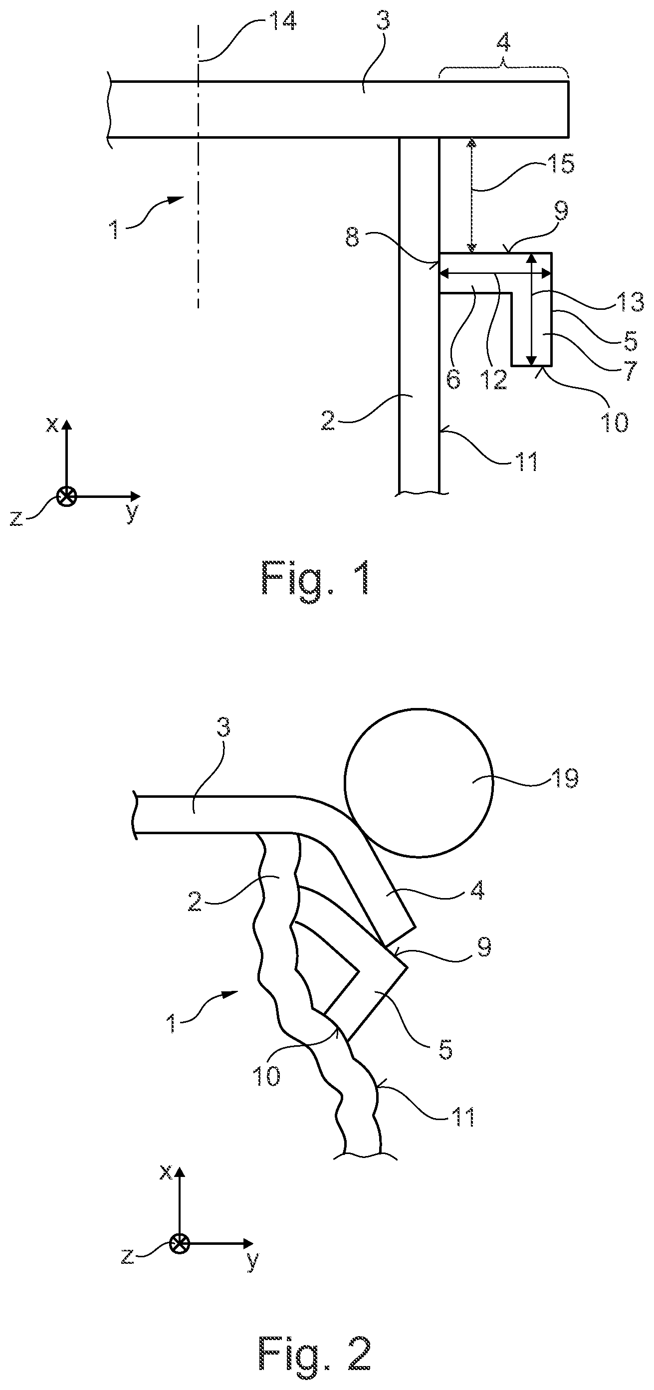
[0022] FIG. 1 shows schematically a detail of a chassis according to the invention in a view from below.
[0023] FIG. 2 shows schematically the chassis shown in FIG. 1 after a collision with an obstacle with a small overlap.
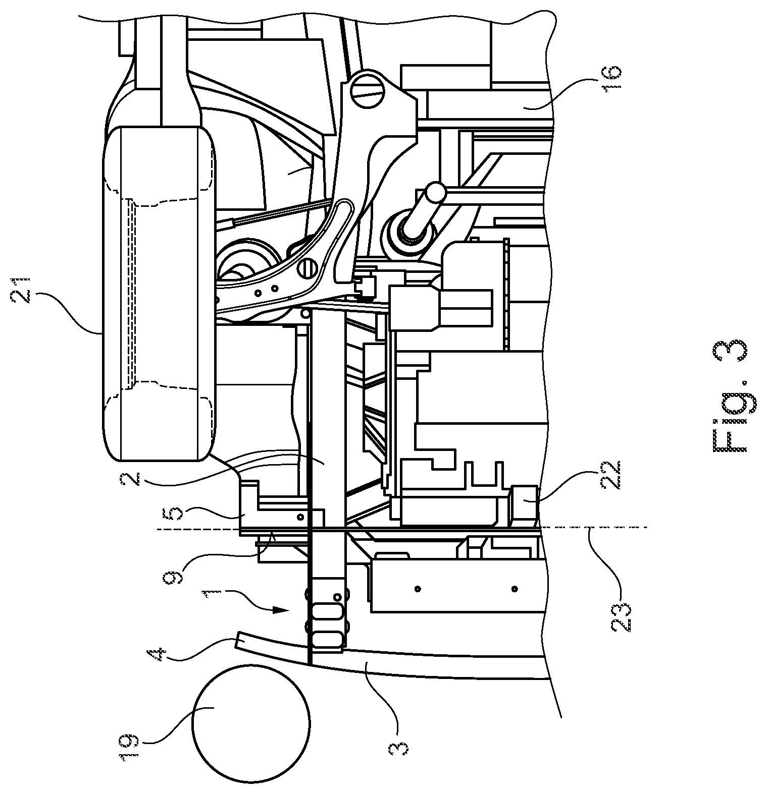
[0024] FIG. 3 shows schematically a detail of a motor vehicle according to the invention in a view from below.
DETAILED DESCRIPTION
[0025] The chassis 1 according to the disclosure shown in FIG. 1 comprises a longitudinal axis 14. The x-direction is defined parallel to this longitudinal axis 14. The y-direction extends horizontally perpendicular to the x-direction and transversely to the longitudinal axis 14. The chassis may include two longitudinal members 2. A front bumper 3 is fastened to the longitudinal member 2. The front bumper 3 extends laterally and/or transversely to the longitudinal axis 14 and to the longitudinal member 2. The front bumper 3 comprises a region 4 protruding in the lateral direction and/or y-direction over the longitudinal member 2 which, for example, has a length of 150 millimeters (150 mm), i.e. protrudes by 150 millimeters over the longitudinal member 2. The chassis 1 additionally comprises a support 5. The support 5 comprises a transverse limb 6 and a longitudinal limb 7.
[0026] The longitudinal member 2 has an outer face 11. The support 5 is fastened at the transverse limb 6 to the outer face 11 of the longitudinal member 2. In the variant shown, the transverse limb 6 has an end face 8. The end face 8 bears against the outer face 11. The end face 8 may be fastened directly to the outer face 11. However, other fastening options are also possible. The transverse limb may, for example, be adhesively bonded and/or screwed and/or welded to the longitudinal member 2.
[0027] The transverse limb 6 extends in the transverse direction, i.e. the y-direction, outwardly. In other words, the transverse limb protrudes to the side outwardly from the outer face 11. The longitudinal limb 7 adjoining the transverse limb 6 to the side on the outside extends in the longitudinal direction, i.e. the x-direction, in the direction remote from the front bumper 3. In other words, the longitudinal limb 7 extends parallel to the longitudinal member 2 toward the rear.
[0028] The support 5 may be designed to be L-shaped, wherein the transverse limb 6 is longer than the longitudinal limb 7. In the variant shown, the transverse limb has a length 12, for example 150 millimeters (150 mm) and the longitudinal limb has a length 13, for example 105 millimeters (105 mm). The length 12 may be greater than the length 13.
[0029] The transverse limb 6 additionally has a front face 9. The support 5 is fastened at the transverse limb to the outer face 11 of the longitudinal member 2 at a spacing 15, for example of 200 millimeters (200 mm) from the front bumper. In the variant shown, the spacing 15 is measured from the front face of the transverse limb to the front bumper 3. The spacing is fixed such that, in the case of a collision with an obstacle with a small overlap, the region 4 of the front bumper 3 protruding in the lateral direction over the longitudinal member is pushed against the support 5 and the support 5 is pushed with its longitudinal limb 7 against the outer face 11 of the longitudinal member 2. In an advantageous variant, the longitudinal limb 7 has an end face 10, wherein in the case of a collision the end face 10 is pushed against the outer face 11 of the longitudinal member 2. This permits an efficient deflection of the load.
[0030] The detail shown in FIG. 1 of a chassis according to the disclosure after a collision is shown schematically in FIG. 2. Due to the collision with an obstacle 19 with a small overlap, the longitudinal member 2 has been deformed. In the situation shown, the transverse limb 6 has also been deformed. The transverse limb has been bent around a vertical axis, i.e. z-axis. The pushing together of the region 4 of the front bumper protruding over the longitudinal member, the transverse limb 6 supported by the longitudinal limb 7 and the longitudinal member 2 produces a stable structure which deflects the load caused by the impact and pushes the vehicle to the side.
[0031] In FIG. 3 a detail of a motor vehicle in a view from below is shown. The motor vehicle may be a truck, a van, a mini-van or a passenger motor vehicle. The motor vehicle 20 includes a number of wheels 21, a drive train 22, a back-up structure 16 which, in particular, includes a driver's cab or a passenger compartment and a chassis 1. In the variant shown, the chassis 1 is located in a position for fastening the drive train 22 by which a front line 23 is defined. In the variant shown, the front face 9 of the transverse limb 6 of the support 5 is aligned with the front line 23 of the position of the drive train 22. The obstacle used for a crash test is identified by the reference numeral 19.
LIST OF REFERENCE NUMERALS
[0032] 1 Chassis [0033] 2 Longitudinal member [0034] 3 Front bumper [0035] 4 Region protruding over the longitudinal member [0036] 5 Support [0037] 6 Transverse limb [0038] 7 Longitudinal limb [0039] 8 End face [0040] 9 Front face [0041] 10 End face [0042] 11 Outer face [0043] 12 Length (y-axis) [0044] 13 Length (x-axis) [0045] 14 Longitudinal axis [0046] 15 Spacing between front bumper and front face [0047] 16 Back-up structure [0048] 19 Obstacle [0049] 20 Motor vehicle [0050] 21 Wheel [0051] 22 Drive train [0052] 23 Front line
* * * * *
D00000
D00001
D00002
XML
uspto.report is an independent third-party trademark research tool that is not affiliated, endorsed, or sponsored by the United States Patent and Trademark Office (USPTO) or any other governmental organization. The information provided by uspto.report is based on publicly available data at the time of writing and is intended for informational purposes only.
While we strive to provide accurate and up-to-date information, we do not guarantee the accuracy, completeness, reliability, or suitability of the information displayed on this site. The use of this site is at your own risk. Any reliance you place on such information is therefore strictly at your own risk.
All official trademark data, including owner information, should be verified by visiting the official USPTO website at www.uspto.gov. This site is not intended to replace professional legal advice and should not be used as a substitute for consulting with a legal professional who is knowledgeable about trademark law.