Cutting Tooth System for a Disk-Saw Felling Head
BREUTZMAN; Mark E.
U.S. patent application number 15/984889 was filed with the patent office on 2019-11-21 for cutting tooth system for a disk-saw felling head. The applicant listed for this patent is Deere & Company. Invention is credited to Mark E. BREUTZMAN.
| Application Number | 20190351494 15/984889 |
| Document ID | / |
| Family ID | 68532698 |
| Filed Date | 2019-11-21 |


| United States Patent Application | 20190351494 |
| Kind Code | A1 |
| BREUTZMAN; Mark E. | November 21, 2019 |
Cutting Tooth System for a Disk-Saw Felling Head
Abstract
A cutting tooth system for a disk of a disk-saw felling head. The disk defines a receiving portion and an axis of rotation. The cutting tooth system comprises at least one cutting tooth. The cutting tooth comprises a first portion defining a first protrusion and a second protrusion. The first portion is configured to be received in the receiving portion for rotation with the disk. A second portion defines a chip removal path and a cutting edge adjacent the chip removal path. A first retaining device is configured to couple to the disk to secure the first protrusion in the receiving portion. A second retaining device is configured to couple to the disk to secure the second protrusion in the receiving portion.
| Inventors: | BREUTZMAN; Mark E.; (Potosi, WI) | ||||||||||
| Applicant: |
|
||||||||||
|---|---|---|---|---|---|---|---|---|---|---|---|
| Family ID: | 68532698 | ||||||||||
| Appl. No.: | 15/984889 | ||||||||||
| Filed: | May 21, 2018 |
| Current U.S. Class: | 1/1 |
| Current CPC Class: | A01G 23/081 20130101; B23D 61/06 20130101; B23D 61/025 20130101; A01G 23/08 20130101 |
| International Class: | B23D 61/06 20060101 B23D061/06; B23D 61/02 20060101 B23D061/02; A01G 23/081 20060101 A01G023/081 |
Claims
1. A cutting tooth system for a disk of a disk-saw felling head, the disk defining a receiving portion and an axis of rotation, the cutting tooth system comprising: at least one cutting tooth comprising: a first portion defining a first protrusion and a second protrusion, the first portion is configured to be received in the receiving portion for rotation with the disk; and a second portion defining a chip removal path and a cutting edge adjacent the chip removal path; a first retaining device configured to couple to the disk to secure the first protrusion in the receiving portion; and a second retaining device configured to couple to the disk to secure the second protrusion in the receiving portion.
2. The cutting tooth system of claim 1, wherein the first protrusion comprises a first curved portion configured for receiving the first retaining device that is cylindrically shaped.
3. The cutting tooth system of claim 1, wherein the second protrusion comprises a second curved portion configured for receiving the second retaining device that is cylindrically shaped.
4. The cutting tooth system of claim 1, wherein the second retaining device comprises a notch positioned to receive the second protrusion.
5. The cutting tooth system of claim 1, wherein the second portion is curved and forms a concave surface that defines the chip removal path.
6. The cutting tooth system of claim 1, wherein the at least one cutting tooth is a first cutting tooth positioned with a first chip removal path positioned in a downward axial direction, further comprising a second cutting tooth positioned with a second chip removal path positioned in an upward axial direction.
7. The cutting tooth system of claim 1, wherein the at least one cutting tooth is a first cutting tooth positioned with a first cutting edge positioned in a downward axial direction, further comprising a second cutting tooth positioned with a second cutting edge positioned in an upward axial direction.
8. A disk-saw felling head comprising: a disk defining a receiving portion and an axis of rotation; a cutting tooth system comprising: at least one cutting tooth comprising: a first portion defining a first protrusion and a second protrusion, the first portion is configured to be received in the receiving portion for rotation with the disk; and a second portion defining a chip removal path and a cutting edge adjacent the chip removal path; a first retaining device coupled to the disk to secure the first protrusion in the receiving portion; and a second retaining device coupled to the disk to secure the second protrusion in the receiving portion.
9. The disk saw felling head of claim 8, wherein the first protrusion comprises a first curved portion configured for receiving the first retaining device that is cylindrically shaped.
10. The disk saw felling head of claim 8, wherein the second protrusion comprises a second curved portion configured for receiving the second retaining device that is cylindrically shaped.
11. The disk saw felling head of claim 8, wherein the second retaining device comprises a notch positioned to receive the second protrusion.
12. The disk saw felling head of claim 8, wherein the second portion is curved and forms a concave surface that defines the chip removal path.
13. The disk saw felling head of claim 8, wherein the at least one cutting tooth is a first cutting tooth positioned with a first chip removal path positioned in a downward axial direction, further comprising a second cutting tooth positioned with a second chip removal path positioned in an upward axial direction.
14. The disk saw felling head of claim 8, wherein the at least one cutting tooth is a first cutting tooth positioned with a first cutting edge positioned in a downward axial direction, further comprising a second cutting tooth positioned with a second cutting edge positioned in an upward axial direction.
15. A method for coupling a cutting tooth system to a disk of a disk-saw felling head, the disk defining a receiving portion and an axis of rotation, the method comprising: providing at least one cutting tooth comprising a first portion defining a first protrusion and a second protrusion, the first portion is configured to be received in the receiving portion for rotation with the disk, and a second portion defining a chip removal path and a cutting edge adjacent the chip removal path; providing a first retaining device coupled to the disk to secure the first protrusion in the receiving portion; and providing a second retaining device coupled to the disk to secure the second protrusion in the receiving portion.
16. The method of claim 15, wherein the first protrusion comprises a first curved portion configured for receiving the first retaining device that is cylindrically shaped.
17. The method of claim 15, wherein the second protrusion comprises a second curved portion configured for receiving the second retaining device that is cylindrically shaped.
18. The method of claim 15, wherein the second retaining device comprises a notch positioned to receive the second protrusion.
19. The method of claim 15, wherein the second portion is curved and forms a concave surface that defines the chip removal path.
20. The method of claim 15, wherein the at least one cutting tooth is a first cutting tooth positioned with a first chip removal path positioned in a downward axial direction, further comprising a second cutting tooth positioned with a second chip removal path positioned in an upward axial direction.
Description
FIELD OF DISCLOSURE
[0001] The present disclosure generally relates to disk-saw felling heads, and more particularly to a system and method for mounting at least one cutting tooth to a disk-saw felling head.
BACKGROUND OF THE DISCLOSURE
[0002] In order to mount a cutting tooth to a disk-saw felling head, the cutting tooth commonly has a blind bore that is threaded and receives a bolt to secure the cutting tooth to a disk of the disk-saw felling head.
SUMMARY OF THE DISCLOSURE
[0003] In one embodiment, a cutting tooth system for a disk-saw felling head is disclosed. A disk defines a receiving portion and an axis of rotation. The cutting tooth system comprising at least one cutting tooth. The cutting tooth comprises a first portion that defines a first protrusion and a second protrusion. The first portion is configured to be received in the receiving portion for rotation with the disk. A second portion defines a chip removal path and a cutting edge adjacent the chip removal path. A first retaining device is configured to couple to the disk to secure the first protrusion in the receiving portion. A second retaining device is configured to couple to the disk to secure the second protrusion in the receiving portion.
[0004] In another embodiment, a disk-saw felling head is disclosed. The disk-saw felling head comprises a disk that defines a receiving portion and an axis of rotation. A cutting tooth system comprises at least one cutting tooth. The cutting tooth comprises a first portion that defines a first protrusion and a second protrusion. The first portion is configured to be received in the receiving portion for rotation with the disk. A second portion defines a chip removal path and a cutting edge adjacent the chip removal path. A first retaining device is coupled to the disk to secure the first protrusion in the receiving portion. A second retaining device is coupled to the disk to secure the second protrusion in the receiving portion.
[0005] In yet another embodiment, a method for coupling a cutting tooth system to a disk of a disk-saw felling head is disclosed. The method comprises providing at least one cutting tooth comprising a first portion and a second portion. The first portion defines a first protrusion and a second protrusion. The first portion is configured to be received in the receiving portion for rotation with the disk. The second portion defines a chip removal path and a cutting edge adjacent the chip removal path. The method further comprises providing a first retaining device coupled to the disk to secure the first protrusion in the receiving portion and providing a second retaining device coupled to the disk to secure the second protrusion in the receiving portion.
[0006] Other features and aspects will become apparent by consideration of the detailed description and accompanying drawings.
BRIEF DESCRIPTION OF THE DRAWINGS
[0007] FIG. 1 is a perspective view of a work vehicle according to one embodiment with a cutting tooth system for a disk of a disk-saw cutting head.
[0008] FIG. 2 is a perspective view of the disk of the work vehicle of FIG. 1.
[0009] FIG. 3 is a perspective view of the cutting tooth system of FIG. 1.
[0010] FIG. 4 is a schematic of an illustrative method for coupling a cutting tooth system to a disk of a disk-saw felling head of a work vehicle.
[0011] Before any embodiments are explained in detail, it is to be understood that the disclosure is not limited in its application to the details of construction and the arrangement of components set forth in the following description or illustrated in the following drawings. The disclosure is capable of other embodiments and of being practiced or of being carried out in various ways. Further embodiments of the invention may include any combination of features from one or more dependent claims, and such features may be incorporated, collectively or separately, into any independent claim.
DETAILED DESCRIPTION
[0012] FIG. 1 illustrates a work vehicle 10 supported by a first set of ground-engagin devices 15 and a second set of ground-engaging devices 20. The first and second sets of ground-engaging devices 15, 20 are configured to move the work vehicle 10 along a surface. The illustrated first set of ground-engaging devices 15 are a first pair of wheels 25. The illustrated second set of ground-engaging devices 20 are a second pair of wheels 30. Alternatively, the first and second sets of ground-engaging devices 15, 20 may be tracks (not shown).
[0013] The work vehicle 10 includes an operator's station 35. The work vehicle 10 may be powered by an engine 40 that is coupled to a transmission (not shown) for transferring power to the first set of ground-engaging devices 15 and the second set of ground-engaging devices 25. The engine 40 may be a diesel engine. Alternatively, the first and second sets of ground-engaging devices 15, 20 may be powered by electric motors (not shown).
[0014] The illustrated work vehicle 10 is a wheeled feller buncher 45. Alternatively, the work vehicle 10 may be a tracked feller buncher (not shown). The work vehicle 10 may include a disk-saw felling head 50 coupled to the work vehicle 10 forwardly 55 of the operator's station 35 for felling trees.
[0015] A linkage assembly 60 allows the disk-saw felling head 50 to be raised, lowered, and tilted to position the disk-saw felling head 50 at a desired position relative to a tree to be felled. The disk-saw felling head 50 includes a support frame 65 supported by the linkage assembly 60. The disk-saw felling head includes saw housing extensions 70, 75 and an accumulation pocket 80 into which felled trees are directed for short-term storage while additional trees are felled. The saw housing extensions 70, 75 generally assist in aligning the disk-saw felling head 50 with a tree to be felled.
[0016] The support frame 65 supports a tree cutting tool assembly 85 that is used to cut a tree trunk from its roots. According to the exemplary embodiment of the present disclosure, the tree cutting tool assembly 85 includes a saw housing 90 and a circular saw blade, or disk, 95 that rotates about an axis of rotation 100.
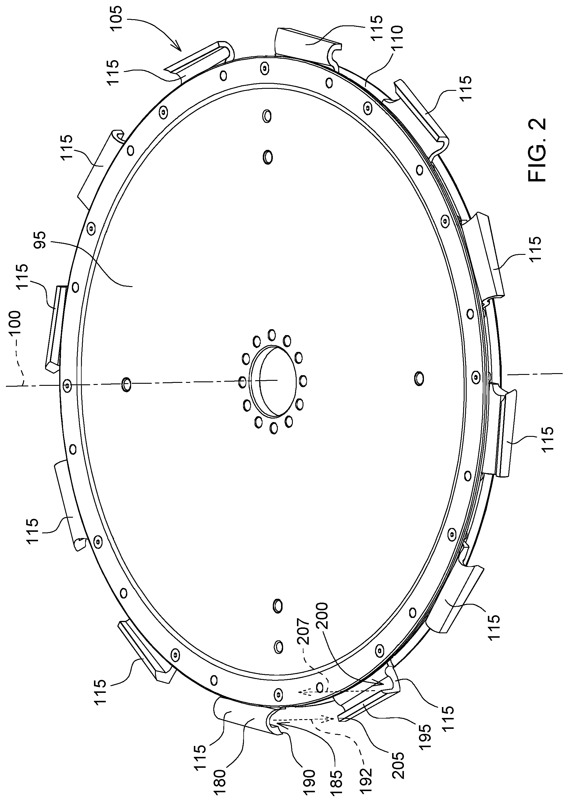
[0017] With reference to FIG. 2, a cutting tooth system 105 is coupled to the disk 95 of the disk-saw felling head 50 for cutting trees. The disk 95 defines a receiving portion 110 for receiving the cutting tooth system 105. The receiving portion 110 may be a groove or a slot formed or machined into the disk 95.
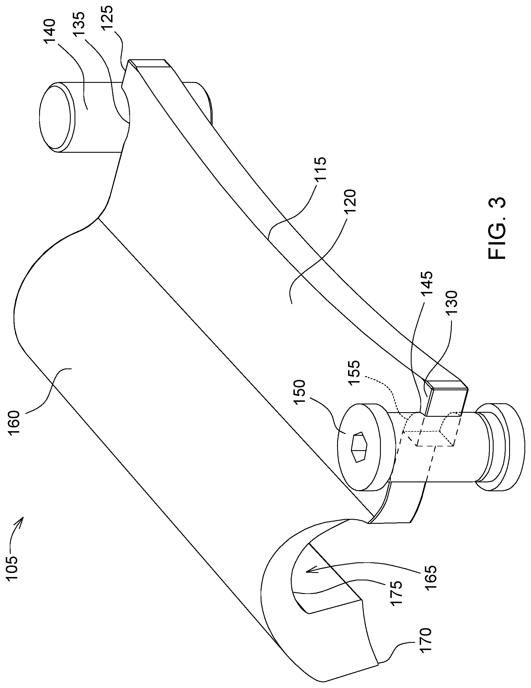
[0018] Referring to FIG. 3, the cutting tooth system 105 comprises at least one cutting tooth 115 comprising a first portion 120 defining a first protrusion 125 and a second protrusion 130. The first portion 120 is configured to be received in the receiving portion 110 for rotation with the disk 95 (FIG. 2).
[0019] With continued reference to FIG. 3, the first protrusion 125 may comprise a first curved portion 135 configured for receiving a first retaining device 140 that is cylindrically shaped. The first curved portion 135 and the first retaining device 140 may be other shapes. The first retaining device 140 may be a fixed pin or other fastener. The first retaining device 140 is configured to couple to the disk 95 to secure the first protrusion 125 in the receiving portion 110.
[0020] The second protrusion 130 may comprise a second curved portion 145 configured for receiving a second retaining device 150 that is cylindrically shaped. The second curved portion 145 and the second retaining device 150 may be other shapes. The second retaining device 150 may comprise a notch 155 positioned to receive the second protrusion 130. The second retaining device 150 may be a fixed pin or a threaded fastener and the notch 155 may be used to secure the cutting tooth 115 in the receiving portion by rotating the second retaining device 150. The second retaining device 150 is configured to couple to the disk 95 to secure the second protrusion 130 in the receiving portion 110.
[0021] The cutting tooth 115 comprises a second portion 160 defining a chip removal path 165 and a cutting edge 170 adjacent the chip removal path 165. The second portion 160 may be curved and form a concave surface 175 that defines the chip removal path 165.
[0022] Referring to FIG. 2, the cutting tooth 115 may be a first cutting tooth 180 that may be positioned with a first chip removal path 185 and a first cutting edge 190 positioned in a downward axial direction 192. A second cutting tooth 195 may be positioned with a second chip removal path 200 and a second cutting edge 205 positioned in an upward axial direction 207. Thus, the first cutting tooth 180 and the second cutting tooth 195 are adjacent and the first chip removal path 185 and the first cutting edge 190 are positioned in opposite directions of the second chip removal path 200 and the second cutting edge 205 forming an alternating pattern. At least one additional cutting tooth 115 may be positioned next to the first and second cutting tooth 180, 195 and continue with the alternating pattern.
[0023] Alternatively, the first and second cutting tooth 180, 195 may be positioned with the first chip removal path 185 and the first cutting edge 190 in the same directions as the second chip removal path 200 and the second cutting edge 205. At least one additional cutting tooth 115 may be positioned next to the first and second cutting tooth 180, 195 with the same orientation of the chip removal path 165 and cutting edge 170. Alternatively, the cutting tooth 115 may be positioned in a pattern that alternates by two or three cutting teeth 115 having the chip removal path 165 and the cutting edge 170 in the same orientation. Other cutting tooth 115 alternating patterns are also contemplated by this disclosure.
[0024] With reference to FIG. 1, the support frame 65 also pivotably supports at least one gathering arm 210 and at least one accumulation arm 215 that gather and hold felled trees in the accumulation pocket 80. The gathering arm 210 is positioned below and is designed to guide cut trees into the accumulation pocket 80, while the accumulation arm 215 is designed to hold the accumulated trees in the accumulation pocket 80.
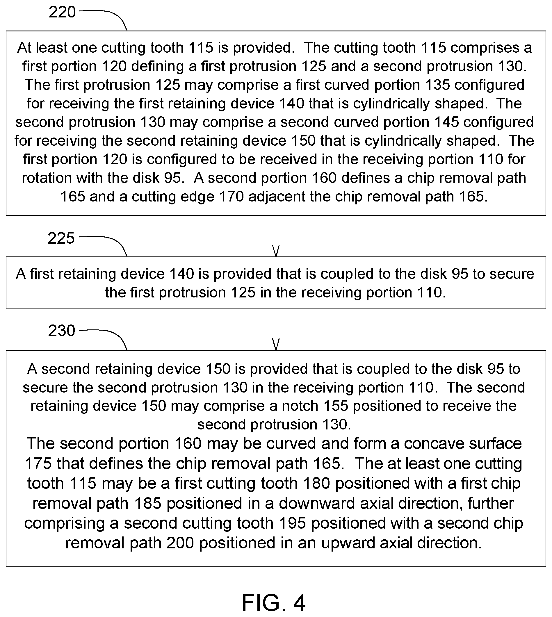
[0025] A method for coupling a cutting tooth system 105 to a disk 95 of a disk-saw felling head 50 is illustrated in FIG. 4. The disk 95 defines a receiving portion 110 and an axis of rotation 100. In Step 220, at least one cutting tooth 115 is provided. The cutting tooth 115 comprises a first portion 120 defining a first protrusion 125 and a second protrusion 130. The first protrusion 125 may comprise a first curved portion 135 configured for receiving the first retaining device 140 that is cylindrically shaped. The second protrusion 130 may comprise a second curved portion 145 configured for receiving the second retaining device 150 that is cylindrically shaped. The first portion 120 is configured to be received in the receiving portion 110 for rotation with the disk 95. A second portion 160 defines a chip removal path 165 and a cutting edge 170 adjacent the chip removal path 165.
[0026] In Step 225, a first retaining device 140 is provided that is coupled to the disk 95 to secure the first protrusion 125 in the receiving portion 110. In Step 230, a second retaining device 150 is provided that is coupled to the disk 95 to secure the second protrusion 130 in the receiving portion 110. The second retaining device 150 may comprise a notch 155 positioned to receive the second protrusion 130.
[0027] The second portion 160 may be curved and form a concave surface 175 that defines the chip removal path 165. The at least one cutting tooth 115 may be a first cutting tooth 180 positioned with a first chip removal path 185 positioned in a downward axial direction, further comprising a second cutting tooth 195 positioned with a second chip removal path 200 positioned in an upward axial direction.
[0028] Various features are set forth in the following claims.
* * * * *
D00000
D00001
D00002
D00003
D00004
XML
uspto.report is an independent third-party trademark research tool that is not affiliated, endorsed, or sponsored by the United States Patent and Trademark Office (USPTO) or any other governmental organization. The information provided by uspto.report is based on publicly available data at the time of writing and is intended for informational purposes only.
While we strive to provide accurate and up-to-date information, we do not guarantee the accuracy, completeness, reliability, or suitability of the information displayed on this site. The use of this site is at your own risk. Any reliance you place on such information is therefore strictly at your own risk.
All official trademark data, including owner information, should be verified by visiting the official USPTO website at www.uspto.gov. This site is not intended to replace professional legal advice and should not be used as a substitute for consulting with a legal professional who is knowledgeable about trademark law.