Aluminum Substrates With Metal-matrix Composite At Feature Areas
Xue; Lijue ; et al.
U.S. patent application number 16/524354 was filed with the patent office on 2019-11-21 for aluminum substrates with metal-matrix composite at feature areas. This patent application is currently assigned to NATIONAL RESEARCH COUNCIL OF CANADA. The applicant listed for this patent is NATIONAL RESEARCH COUNCIL OF CANADA. Invention is credited to Yangsheng Li, Shaodong Wang, Lijue Xue.
| Application Number | 20190351486 16/524354 |
| Document ID | / |
| Family ID | 45496405 |
| Filed Date | 2019-11-21 |


| United States Patent Application | 20190351486 |
| Kind Code | A1 |
| Xue; Lijue ; et al. | November 21, 2019 |
ALUMINUM SUBSTRATES WITH METAL-MATRIX COMPOSITE AT FEATURE AREAS
Abstract
A substrate has a body defined at least in part by a single piece of aluminum or aluminum alloy material having a cavity and a pinch-off or other feature area and further having a metal-matrix composite (MMC) layer formed integrally in the body at the pinch-off or other feature area. A process of producing a substrate involves machining a single piece of material to provide a body having a surface and a feature area, the feature area being of smaller dimension than required for the piece, integrally forming a metal-matrix composite layer in the feature area to build up the feature area to at least a dimension required for the piece. The metal-matrix composite comprises an aluminum-nickel alloy matrix (e.g. Al-12Si alloy alloyed with Ni) having WC particles embedded therein or a aluminum matrix (e.g. Al-12Si alloy) having TiC particles embedded therein and has greater wear resistance, greater strength, greater toughness or any combination thereof than the material.
| Inventors: | Xue; Lijue; (London, CA) ; Wang; Shaodong; (London, CA) ; Li; Yangsheng; (London, CA) | ||||||||||
| Applicant: |
|
||||||||||
|---|---|---|---|---|---|---|---|---|---|---|---|
| Assignee: | NATIONAL RESEARCH COUNCIL OF
CANADA Ottawa CA |
||||||||||
| Family ID: | 45496405 | ||||||||||
| Appl. No.: | 16/524354 | ||||||||||
| Filed: | July 29, 2019 |
Related U.S. Patent Documents
| Application Number | Filing Date | Patent Number | ||
|---|---|---|---|---|
| 13811407 | Jan 22, 2013 | 10363605 | ||
| 16524354 | ||||
| 12886936 | Sep 21, 2010 | |||
| PCT/CA2011/000838 | Jul 21, 2011 | |||
| 13811407 | ||||
| 61366740 | Jul 22, 2010 | |||
| Current U.S. Class: | 1/1 |
| Current CPC Class: | B29C 2049/4892 20130101; B29C 49/04 20130101; B29C 2049/4897 20130101; B29C 49/4823 20130101; B29L 2031/7158 20130101; B29C 49/48 20130101; B29C 49/06 20130101; B29C 33/38 20130101; B29C 33/56 20130101; B29C 2049/4874 20130101; B29K 2905/02 20130101; B22F 5/007 20130101 |
| International Class: | B22F 5/00 20060101 B22F005/00; B29C 33/56 20060101 B29C033/56 |
Claims
1. A substrate, composed of Al or an alloy thereof, with a cladding of a wear resistant metal matrix ceramic (MMC) comprising: a Ni bearing Al alloy matrix with particles of WC; or an Al matrix with particles of TiC, where the cladding is metallurgically bonded to the substrate, and the WC or TiC particles are distributed in the matrix in an amount in a range of from 5 to 50%, based on a weight of the composite.
2. The substrate according to claim 1 wherein the Al alloy of which the substrate is composed comprises: Al 2024 all, Al 2124 all, Al 2219 T31 through T87, Al 6009 all, Al 6010 all, Al 6061 T4 through T6511, Al 7075 T6 through T7351, Al 7050 all or Al 7475 all.
3. The substrate according to claim 2 wherein the Al alloy of which the substrate is composed comprises Al 7075 T6 through T7351.
4. The substrate according to claim 1 wherein the substrate is clad at feature areas thereof and not at a surface of the substrate away from the feature areas, whereby the cladding is not a coating.
5. The substrate according to claim 1 wherein the matrix comprises Al-1251 alloy.
6. The substrate according to claim 1 wherein the matrix comprises Al 4047.
7. The substrate according to claim 1 wherein the WC or TiC particles are distributed in the matrix in an amount in a range of from 10 to 40%, based on the weight of the composite.
8. The substrate according to claim 1 wherein the WC or TiC particles are distributed in the matrix in an amount in a range of from 20 to 35%, based on the weight of the composite.
9. The substrate according to claim 1 wherein the MMC layer has a microstructure consistent with formation by laser cladding.
10. The substrate according to claim 1 wherein cladding has a wear resistance of at least about 5 times that of the substrate.
11. The substrate according to claim 1 wherein the cladding comprises WC particles.
12. The substrate according to claim 11 wherein the cladding has a Vickers hardness (Hv0.5) of about 200.
13. The substrate according to claim 11 wherein the matrix comprises 1.5-5.4% Ni based on weight of the composite.
14. The substrate according to claim 11 wherein the matrix comprises 2.4-3.6% Ni based on weight of the composite.
15. The substrate according to claim 11 wherein the matrix comprises about 3% Ni based on weight of the composite.
16. The substrate according to claim 11 wherein the embedded particles are distributed in the aluminum-nickel alloy matrix in an amount of about 27%, based on the weight of the composite.
17. The substrate according to claim 1 wherein the cladding comprises TiC particles.
18. The substrate according to claim 17 wherein the cladding has the embedded particles distributed in the aluminum-nickel alloy matrix in an amount of about 30%, based on the weight of the composite.
Description
CROSS-REFERENCE TO RELATED APPLICATIONS
[0001] This application is continuation of, and claims priority under 35 U.S.C. .sctn. 120 to, U.S. application Ser. No. 13/811,407, filed Jan. 22, 2013, which is continuation-in-part of, and claims priority under 35 U.S.C. .sctn. 120 to, U.S. application Ser. No. 12/886,936, filed on Sep. 21, 2010, which was a U.S. National Stage of, filed under 35 U.S.C. .sctn. 371 of PCT/CA2011/000838, filed on Jul. 21, 2011, which claims benefit of U.S. Provisional App. No. 61/366,740, filed on Jul. 22, 2010, the entire contents of which are herein incorporated by reference herein.
FIELD OF THE INVENTION
[0002] The present invention relates to aluminum substrates clad with metal matrix composites.
BACKGROUND OF THE INVENTION
[0003] Aluminum alloys are typically used to make blow mold halves, mold halves for other forming, and substrates in general for tooling or parts, due to their good thermal conductivity, light weight and ease of machining. However, aluminum alloys are usually soft and have relatively inferior wear resistance. In order to extend life, inserts made of hard and tough metals (typically, beryllium-copper or hardened steel) are sometimes used at areas that provide special features in the aluminum (FIG. 1). However, these inserts have to be machined separately from and fastened onto the substrates, which significantly increases the complexity of the design and increases production cost and time for manufacturing and assembling of these inserts. Due to the addition of these inserts, cooling channels may have to be designed beneath the inserts, which may restrict the effectiveness of the cooling. In addition, beryllium-copper material typically used to make these inserts is quite expensive and more difficult to machine.
[0004] One-piece aluminum substrates that eliminate insert segments (FIG. 2) simplify design, as they reduce the effort expended to ensure that the various inserts align properly with one another upon assembly. One-piece aluminum substrates may be constructed relatively quickly, as compared to substrates with insert segments, and at low cost. Heat transfer performance is also enhanced over segmented substrates, as thermal breaks formed by the junctions of aligned parts are eliminated.
[0005] Methods are known that use explosive cladding (or roll cladding, diffusion bonding, etc.) to metallurgically bond a very hard metal layer (such as steel, titanium, etc.) to a softer but very thermally conductive metal substrate (such as an aluminum alloy). One problem with technologies such as these is that the layer of very hard metal has different thermal properties than the substrate leading to cracking, especially under prolonged usage. Extra layers of other thermally conductive material may be employed to mitigate against cracking, but this complicates the process and does not satisfactorily address the cracking problem.
[0006] Prior to the making of this invention, it was not known what materials can metallurgically bond to Al or Al-alloy substrates to improve wear resistance, without cracking, peeling, or decomposition of the ceramic during cladding. There remains a need in the art for further improvement to aluminum substrates with layers of metal-matrix composite at feature areas.
SUMMARY
[0007] Thus, there is provided a part or piece comprising a body defined at least in part by a single piece of aluminum or aluminum alloy material comprising a surface and a feature area and further comprising a layer of a metal-matrix composite (MMC) formed integrally therein at the feature area, the MMC comprising an aluminum-nickel alloy matrix having WC particles embedded therein or an aluminum matrix having TiC particles embedded therein.
[0008] There is further provided a process of producing a piece comprising: machining a single piece of aluminum or aluminum alloy material to provide a body comprising a surface and a feature area, the feature area being of smaller dimension than required for the piece; and integrally forming a layer of a metal-matrix composite (MMC) in the feature area to build up the feature area to at least a dimension required for the aluminum substrate, the MMC comprising an aluminum-nickel alloy matrix having WC particles embedded therein or an aluminum matrix having TiC particles embedded therein.
[0009] A layer of the MMC may be formed integrally in one, or more feature areas.
[0010] The MMC layer comprises an aluminum matrix. For the aluminum matrix, aluminum alloys are particular useful, for example Al 2024 all, Al 2124 all, Al 2219 T31 through T87, Al 6009 all, Al 6010 all, Al 6061 T4 through T6511, Al 7075 T6 through T7351, Al 7050 all and Al 7475 all. Al-12Si alloys are particularly preferred. Al-12Si alloys are identified in the art as Al 4047 and comprise aluminum alloyed with about 11-13 wt % (nominally about 12 wt %) silicon, based on total weight of the alloy. Embedded in the relatively soft aluminum matrix are hard and wear resistant particles of a tungsten carbide (WC) or titanium carbide (TiC). When WC particles are embedded, the aluminum matrix is an aluminum-nickel alloy matrix. When TiC particles are embedded, the aluminum matrix is a matrix without alloyed nickel.
[0011] The nickel in the aluminum-nickel alloy matrix may be alloyed with the aluminum alloy prior to embedding the tungsten carbide (WC) particles, or more preferably, during the embedding process. During the embedding process, a WC/Ni material may be used in which the nickel acts as a binder for the WC particles in the material. During the embedding process, the nickel is melted and dissolves in the aluminum alloy to form the aluminum-nickel alloy matrix while the WC particles are only partially melted and remain as hard particulates embedded in the matrix. The Ni that dissolves in the aluminum alloy interacts with the aluminum alloy to form intermetallics that further increase matrix hardness.
[0012] WC or TiC particles are embedded in the matrix in any amount suitable to provide sufficiently greater wear resistance, strength and/or toughness at the feature areas to satisfactorily extend the working life of the piece. The amount of WC or TiC distributed in the matrix is preferably in a range of from about 5 wt % to about 50 wt %, based on the weight of the composite, more preferably about 10-40 wt %, for example about 20-35 wt %. When used, the amount of nickel alloyed in the matrix of the composite is preferably in a range of from about 1.5 wt % to about 5.5 wt %, based on the weight of the composite, more preferably about 2.4-3.6 wt %, for example about 3 wt %.
[0013] The MMC layer has greater wear resistance, strength and/or toughness than the aluminum or aluminum alloy into which the MMC is integrally formed, thereby providing greater resistance to high pressures and mechanical stresses. Further, the MMC layer has good bonding and compatibility to the material so that the interface and surrounding areas will not induce crack or peel-off. The MMC has a similar coefficient of thermal expansion compared to the material, which reduces the likelihood of cracking or other damage to the aluminum substrate due to changes in temperature.
[0014] The material comprises aluminum or an aluminum alloy. Some examples of suitable aluminum alloys include Al 2024 all, Al 2124 all, Al 2219 T31 through T87, Al 6009 all, Al 6010 all, Al 6061 T4 through T6511, Al 7075 T6 through T7351, Al 7050 all and Al 7475 all. It should be noted that all aluminum alloys have excellent thermal properties but other materials with high strength and heat-treated properties are generally chosen when improved wear, strength and thermal properties are necessary in combination.
[0015] The MMC layer may be formed in the feature area by any suitable process. The MMC layer may be formed by adding the MMC material to, or by otherwise modifying the surface of, the body in the feature area. In some instances, it may be desirable to form the MMC layer in different feature areas using different processes. The process or processes used to add and/or modify the feature area are preferably very well controlled so that the features are accurately engineered at the desired locations and are integrally formed in the body, e.g. by metallurgical bonding. Preferably, the process has minimal effect on the material in order to reduce potential distortion and property deterioration of the body. Thickness of the MMC layer depends on working conditions and the process used to create the layer. For example, thicknesses may be from about several nanometers to several tens of millimeters.
[0016] In one preferred embodiment, an MMC layer may be formed by first engineering a body in which feature area is machined to an undersized dimension, and then adding MMC material to the feature area to build up the feature to final dimension. In a variation of this embodiment, the feature area may be built up with MMC material beyond final dimension and then machined down to final dimension.
[0017] There is also provided a substrate, composed of Al or an alloy thereof, with a cladding of a wear resistant metal matrix ceramic (MMC) comprising: a Ni bearing Al matrix with particles of WC; or an Al matrix with particles of TiC, where the cladding is metallurgically bonded to the substrate, and the WC or TiC particles are distributed in the matrix in an amount in a range of from 5 to 50%, based on a weight of the composite.
[0018] The substrate may comprise Al 2024 all, Al 2124 all, Al 2219 T31 through T87, Al 6009 all, Al 6010 all, Al 6061 T4 through T6511, Al 7075 T6 through T7351, Al 7050 all or Al 7475 all. More preferably, the substrate may comprise Al 7075 T6 through T7351.
[0019] The matrix may comprise Al-12Si alloy. The WC or TiC particles may be distributed in the matrix in an amount in a range of from 10 to 40 wt %, or 20 to 35 wt %, based on the weight of the composite. The MMC layer may be formed by laser cladding.
[0020] The cladding may have a wear resistance of at least about 5 times that of the substrate.
[0021] If the cladding is the MMC with WC particles, the cladding may have: a Vickers hardness (Hv0.5) of about 200; within the matrix, 1.5-5.4%, more preferably 2.4-3.6%, and more preferably about 3%, Ni based on weight of the composite; the embedded particles distributed in the aluminum-nickel alloy matrix in an amount of about 27%, based on the weight of the composite.
[0022] If the cladding is the MMC with TiC particles, the cladding may have the embedded particles distributed in the aluminum-nickel alloy matrix in an amount of about 30%, based on the weight of the composite.
[0023] Various processes may be used to form the MMC layer. Such processes include, for example, laser cladding, laser alloying, electron beam cladding, electron beam alloying, brazing, diffusion bonding, friction stir welding, laser assisted thermal spray, laser assisted cold spray, low heat input welding (e.g. micro plasma welding), aluminum anodizing, ion implantation, chemical vapor deposition, plasma enhanced physical vapor deposition, diffusion coating, plasma treating, electroplating and electroless plating.
[0024] Laser cladding is a process that enables metallurgical bonding of MMC material to the body to build up a relatively thick layer of the MMC layer in the feature area. Compared to conventional welding, laser cladding involves much better control and much less heat input, which reduces distortion and property deterioration in the body. As a variation, laser alloying may be used to melt the surface layer of the body to permit addition of various alloying elements to enhance surface hardness and wear resistance in the feature area. In another variation, an electron beam may be used instead of or in addition to a laser as the heating source for cladding.
[0025] In the present invention, the feature areas are built up and/or enhanced with a specifically engineered MMC material. The specific requirements for each feature area can be met by tailoring the specifically engineered MMC material without affecting the material used to make bodies. Metallurgical bonding between the MMC material and the material offers good compatibility between the two materials, which ensures long life of the feature areas during high pressure and high cycle rate operations.
[0026] Further, parts having a very hard metal layer (such as steel, titanium, etc.) metallurgically bonded to a softer but very thermally conductive aluminum or aluminum alloy substrate suffer from thermal incompatibility between the cladding layer and the body leading to cracking, thereby shortening the effective working life. The present aluminum substrates combine wear resistance, strength and/or toughness with good thermal compatibility at the feature areas to provide significantly extended working lives.
[0027] Furthermore, the present invention may be used not only on flat parting surfaces but may also be advantageously used on contoured parting surfaces. There is no restriction on substrate size. The present invention may be used to produce any article that may be formed. Some examples of articles include containers (e.g. bottles), automotive components, recreational components, industrial components and chemical components, especially containers.
[0028] Further features of the invention will be described or will become apparent in the course of the following detailed description.
BRIEF DESCRIPTION OF THE DRAWINGS
[0029] In order that the invention may be more clearly understood, embodiments thereof will now be described in detail by way of example, with reference to the accompanying drawings, in which:
[0030] FIG. 1 is a schematic drawing of a traditional substrate with insert segments;
[0031] FIG. 2 is a schematic drawing of a substrate in accordance with U.S. Pat. No. 7,531,124;
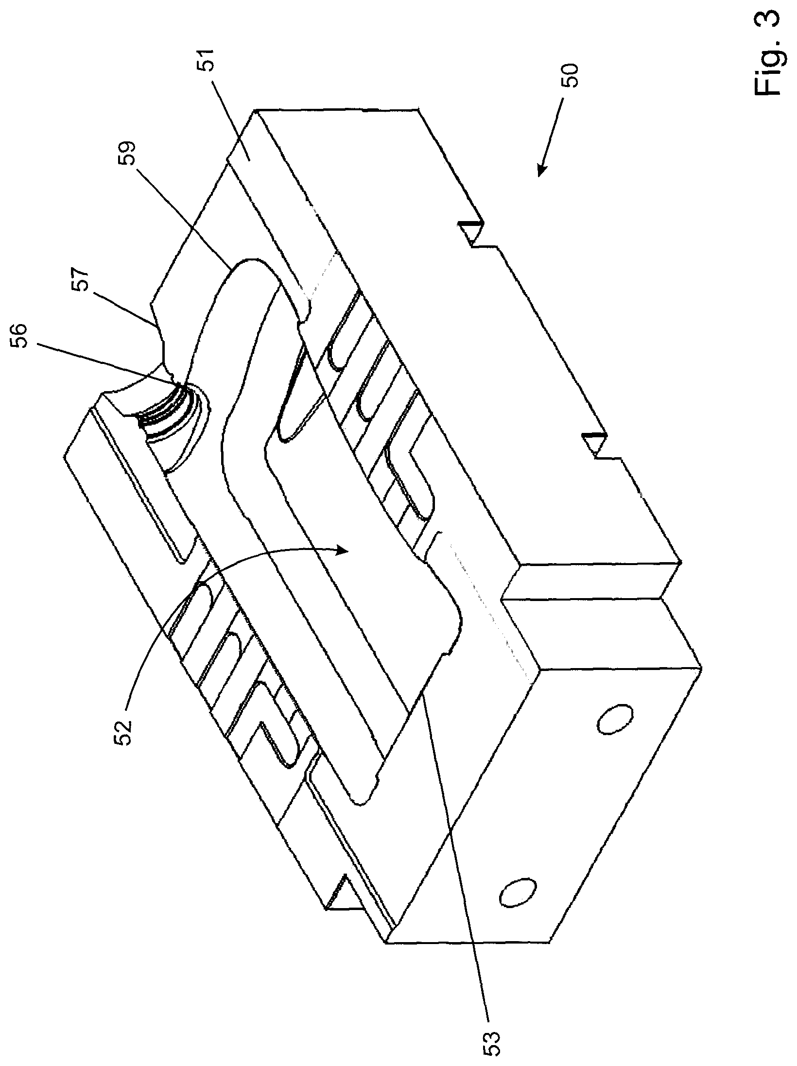
[0032] FIG. 3 is a schematic drawing of one embodiment of a substrate pre-machined to an undersized shape at feature areas;
[0033] FIG. 4 is a schematic drawing of one embodiment of a metal-matrix composite (MMC) layer integrated on to the substrate of FIG. 3 at the feature areas, where FIG. 4A shows the MMC layer with an initial excess of MMC material and FIG. 4B shows the MMC layer after being machined to final dimension;
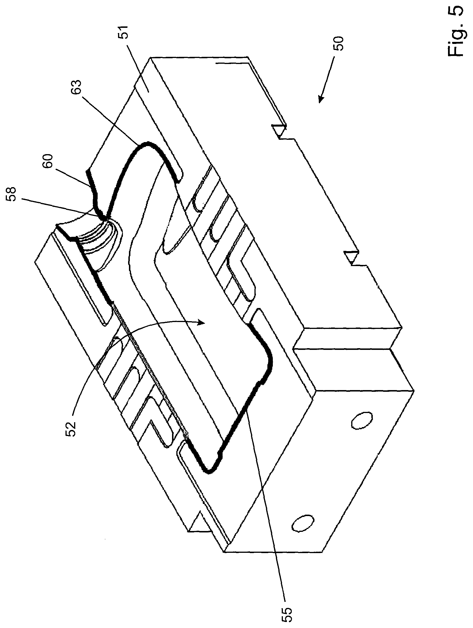
[0034] FIG. 5 is a schematic drawing of a substrate of the present invention having a metal-matrix composite layer integrated at feature areas;
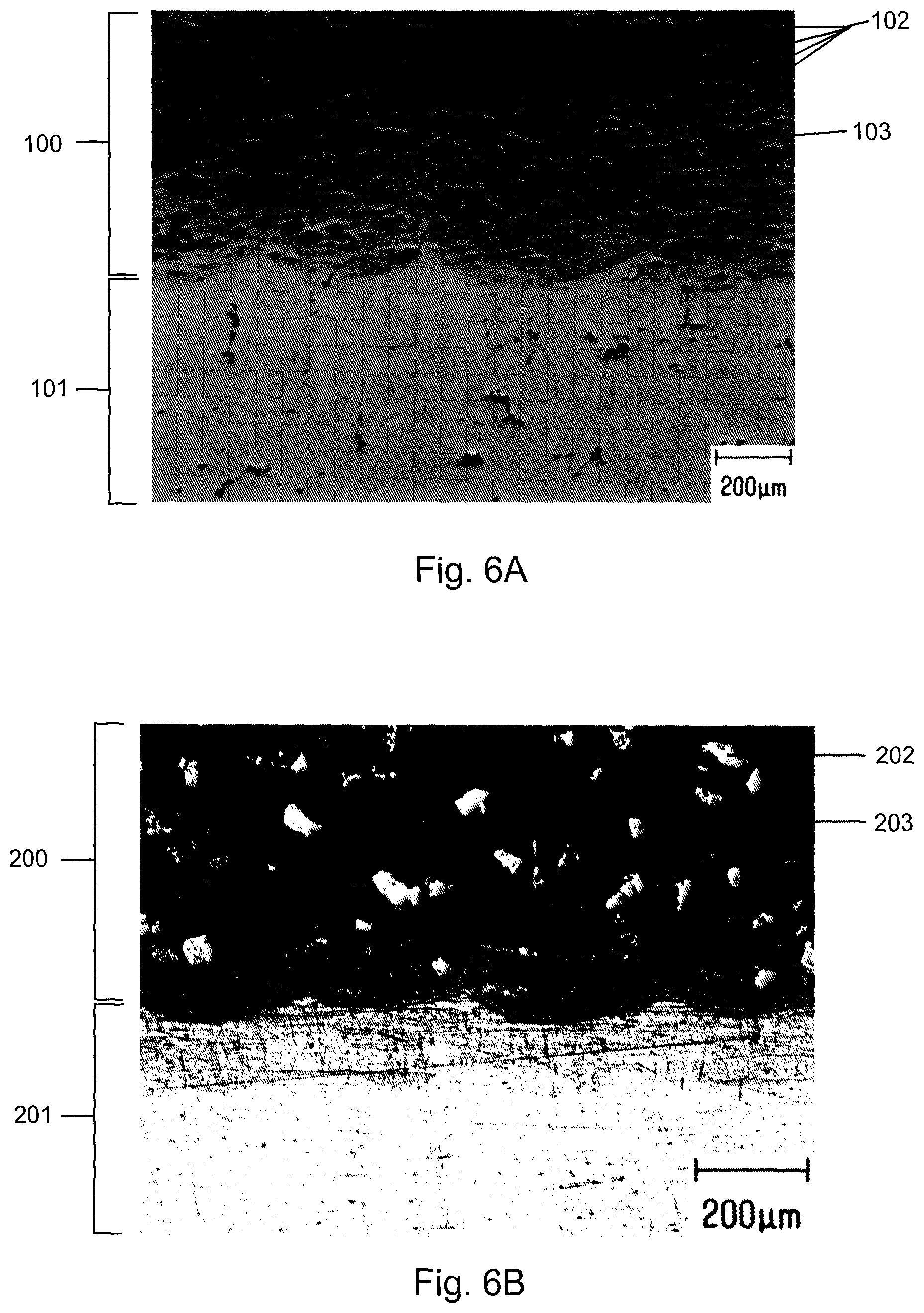
[0035] FIG. 6A depicts microstructure of a cross-section of a Al 7075-T651 substrate clad with a Al 4047+30% (90% WC+10% Ni) metal-matrix composite layer;
[0036] FIG. 6B depicts microstructure of a cross-section of a Al 7075-T651 substrate clad with a Al 4047+30% (TiC) metal-matrix composite layer;
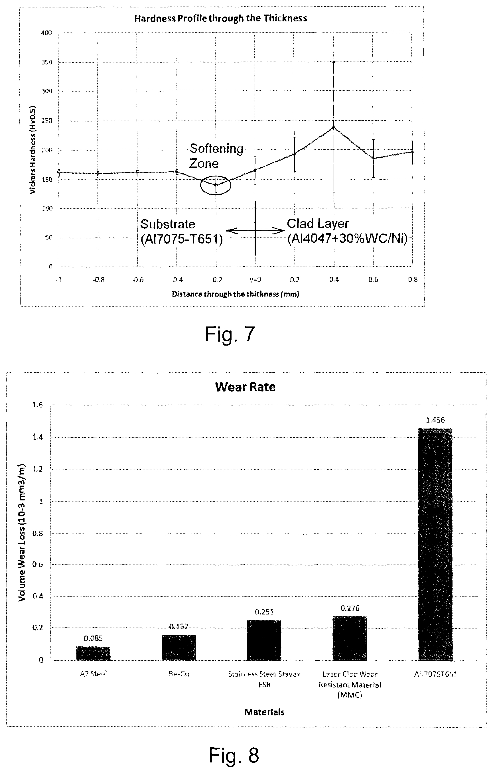
[0037] FIG. 7 depicts a graph showing hardness depth profile of Al 4047+30% (90% WC+10% Ni) metal-matrix composite layer clad on Al 7075-T651 substrate;
[0038] FIG. 8 depicts a graph comparing Vickers hardness of Al 4047+30% (90% WC+10% Ni) metal-matrix composite layer to that of Al 7075-T651, A2 steel, Be--Cu alloy and Stainless Steel Stavex ESR; and,
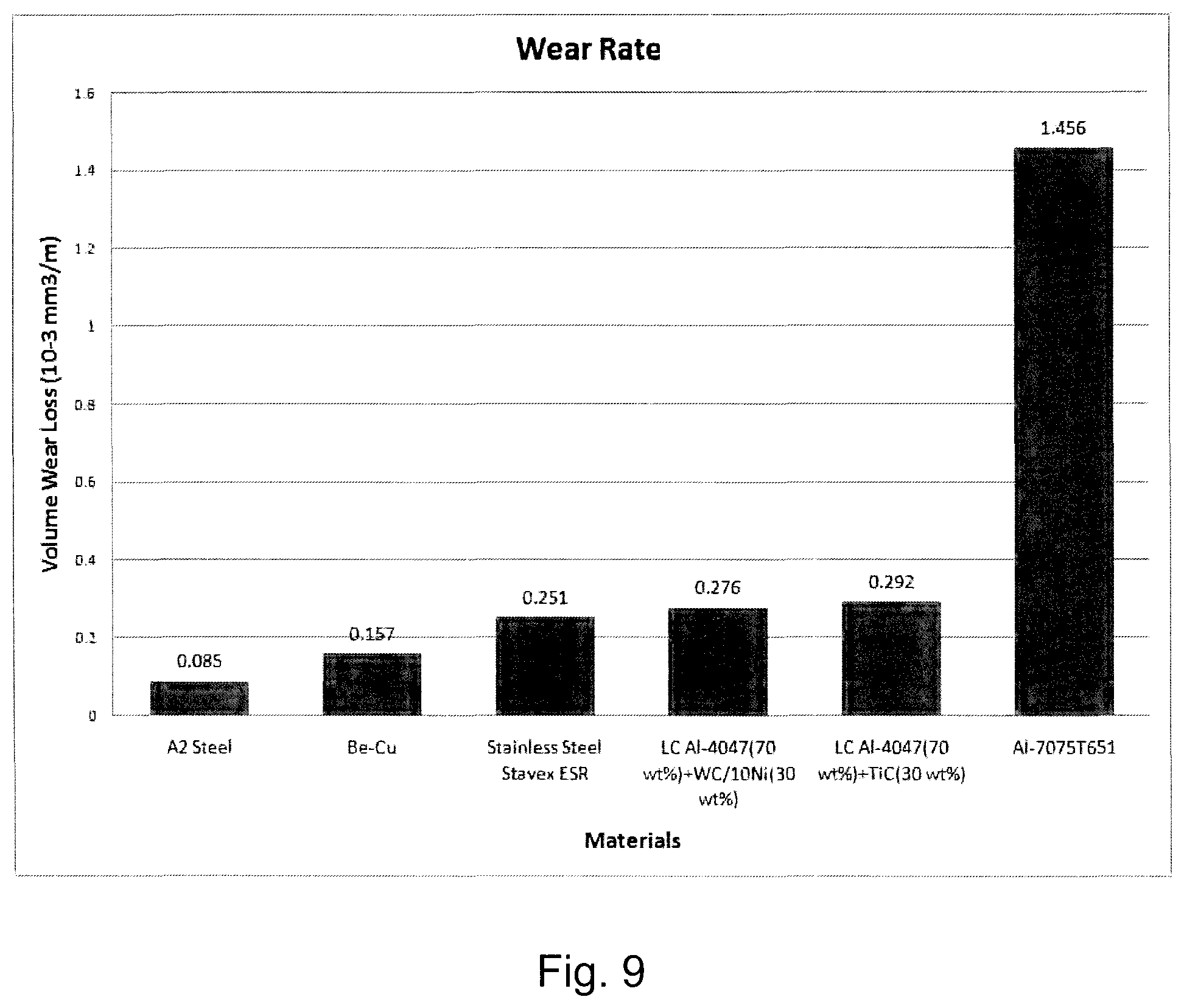
[0039] FIG. 9 depicts a graph comparing wear loss of Al 4047+30% (90% WC+10% Ni) and Al 4047+30% (TiC) metal-matrix composite layer to that of Al 7075-T651, A2 steel, Be--Cu alloy and Stainless Steel Stavex ESR.
DESCRIPTION OF PREFERRED EMBODIMENTS
[0040] FIG. 1 depicts a traditional substrate for a bottle blow mold in which insert segments are used in the pinch-off and other feature areas. Thus, substrate 10 has a body 11 having cavity 12. Pinch-off insert segment 14 comprising raised pinch-off area 15 is inserted into pinch-off insert area 13 of the body and secured to the body by bolts. Bottle top thread insert 17 comprising raised thread feature 18 and bottle top insert 19 comprising raised bottle top feature 20 are inserted into bottle top feature insert area 16 of the body and secured to the body by bolts. Bottle shoulder insert 22 comprising raised shoulder feature 23 is inserted into shoulder insert area 29 of the body and secured to the body by bolts.
[0041] FIG. 2 depicts a substrate for a bottle blow mold in accordance with U.S. Pat. No. 7,531,124. Substrate 30 includes a body 31 having cavity 32, raised pinch-off area 35, raised thread feature 38, raised bottle top feature 40 and raised shoulder feature 43. The body, pinch-off area and all three features comprise the same material.
[0042] FIGS. 3-5 depict one embodiment of a substrate for a bottle blow mold in accordance with the present invention at various stages of fabrication. Referring to FIG. 3, substrate 50 comprising aluminum alloy body 51 and cavity 52 is pre-machined to an undersized shape at pinch-off area 53, thread feature area 56, bottle top feature area 57 and shoulder feature area 59. Referring to FIG. 4A, in order to complete the substrate, a layer of MMC material is laser clad at pinch-off area 53 (and the other feature areas not shown in FIG. 4) to provide raised layer 70 of the cladding material having excess portion 71. In order to avoid undercut and/or mismatch, body 51 at each side of raised layer 70 is rough machined prior to the laser cladding step to leave spare layer 72 of material at each side of raised layer 70. After the cladding step, spare layer 72 is machined off along with excess portion 71 of the cladding material to bring body 51 and raised layer 70 to final dimension (FIG. 4B). For certain processes, the spare layer may not be necessary provided no undercut and/or mismatch between the MMC material and the body occurs. Referring to FIG. 5, after cladding, substrate 50, having body 51 and cavity 52, comprises clad pinch-off area 55 and clad other feature areas 58, 60 and 63 in which an MMC layer is integrally formed.
Example 1: Laser Cladding of Al 7075-T651 Substrate with Al 4047+WC/Ni
[0043] Laser cladding was performed by using a focused Nd:YAG laser beam with a 115-mm focal length lens. A powder feeder was used to simultaneously deliver Al 4047 and WC/Ni powder mixture through a feed nozzle into the melt pool at a rate of about 2 g/min. The laser beam and powder feeding nozzle were kept stationary, while the Al-7075-T561 substrate was moved under the beam by a CNC motion system. The cladding was conducted with an average laser power up to 500 W with a beam diameter of about 1 mm. A laser pulse duration of 10 ms and a frequency of 10 Hz were used for the processing. An overlap ratio of 30% was used between passes to produce multi-passes to cover the required area, while a z movement of about 130 .mu.m was used to deposit multi-layers to reach the required height.
Example 2: Laser Cladding of Al 7075-T651 Substrate with Al 4047+TiC
[0044] Laser cladding was performed by using a focused Nd:YAG laser beam with a 115-mm focal length lens. A powder feeder was used to simultaneously deliver Al 4047 and TiC powder mixture through a feed nozzle into the melt pool at a rate of about 2 g/min. The laser beam and powder feeding nozzle were kept stationary, while the Al-7075-T561 substrate was moved under the beam by a CNC motion system. The cladding was conducted with an average laser power up to 500 W with a beam diameter of about 1 mm. A laser pulse duration of 10 ms and a frequency of 10 Hz were used for the processing. An overlap ratio of 30% was used between passes to produce multi passes to cover the required area, while a z movement of about 200 .mu.m was used to deposit multi-layers to reach the required height.
Example 3: Microstructure Analysis of Clad Substrates
[0045] In a preliminary experiment, a layer of Al 4047 (which is the matrix material of the metal-matrix composite) was laser clad on to Al 7075-T651 substrate by a modification of the procedure of Example 1 in order to examine the microstructure of the clad specimen. This was compared to a similar specimen in which a layer of Al 7075 was clad on to Al 7075-T651 substrate. Examination by optical microscopy of a cross-section of the specimens showed that cladding with Al 7075 showed a tendency for cracking while cladding with Al 4047 produce a good metallurgical bond without inducing cracks or pores in the clad layer. Further, the laser clad Al 4047 layer showed good machinability, a smooth transition of hardness from the substrate to the clad layer, and a generally uniform hardness through the layer. Finally, a polishing test showed that the laser clad Al 4047 layer is superior to the Al 7075-T651 substrate in polishing.
[0046] With reference to FIG. 6A, microstructure analysis was extended to a metal-matrix composite (MMC) in which Al 4047+30% (90% WC+10% Ni) MMC layer 100 was laser clad on to Al 7075-T651 substrate 101 in accordance with the process in Example 1. The MMC comprises WC particles embedded in an Al 4047/Ni matrix formed using 30 wt % WC/Ni material. The WC/Ni material consists of 90 wt % WC (tungsten carbide) and 10 wt % Ni (nickel). Thus, the amount of WC in the MMC layer is about 27 wt % and the amount of nickel alloyed with the Al 4047 is about 3 wt %, based on the weight of the MMC. A good metallurgical bond was formed with no formation of cracks or pores in the MMC layer. Further, in the MMC layer, WC hard particles 102 were evenly distributed in Al 4047/Ni matrix 103, while the Ni from the WC/Ni material dissolved in the Al 4047 to form intermetallics that further increase matrix hardness. Similar experiments were performed with other metal-matrix composites, i.e. Al 4047+Al.sub.2O.sub.3 and Al 4047+WC/Co. In the case of Al 4047+Al.sub.2O.sub.3, laser cladding did not generate hardening, probably due to the decomposition of Al.sub.2O.sub.3 during the cladding process. In the case of Al 4047+WC/Co, the clad layer had improved wear resistance but showed a tendency to crack.
[0047] With reference to FIG. 6B, microstructure analysis was extended to a metal-matrix composite (MMC) in which Al 4047+30% (TiC) MMC layer 200 was laser clad on to Al 7075-T651 substrate 201 in accordance with the process in Example 2. The MMC comprises TiC particles embedded in an Al 4047 matrix formed using 30 wt % TiC material. A good metallurgical bond was formed with no formation of cracks or pores in the MMC layer. Further, in the MMC layer, TiC hard particles 202 were evenly distributed in Al 4047 matrix 203.
Example 4: Microhardness Analysis of Clad Substrates
[0048] A Vickers hardness test (ASTM E384--10e2) was conducted on the laser clad products of Examples 1 and 2 using a load of 500 g for 15 s at evenly distributed points spaced by 0.2 mm. FIG. 7 depicts hardness depth profile of the Al 4047+30% (90% WC+10% Ni) MMC layer clad on the Al 7075-T651 substrate. It is evident from FIG. 7 that the Al 4047+30% (90% WC+10% Ni) is harder than the Al 7075-T651 substrate. The substrate near the clad layer has a softening zone with a Vickers hardness (Hv0.5) of around 140, perhaps due to annealing induced by laser cladding. There was a larger deviation in the hardness of laser clad (Al 4047+30% (90% WC+10% Ni)) layer due to heterogeneous features in the MMC.
[0049] Further, with reference to FIG. 8, Vickers hardness of the Al 4047+30% (90% WC+10% Ni) MMC layer was compared to that of the Al 7075-T651 and other typical insert materials (i.e. A2 steel, Be--Cu alloy and Stainless Steel Stavex ESR). Table 1 summarizes the results and includes the hardness of the Al 4047+30% (TiC) MMC layer. Table 1 and FIG. 8 demonstrate that the Al 4047+30% (90% WC+10% Ni) layer is harder than Al 7075-T651 and approaches that of the steels. Table 1 demonstrates that the Al 4047+30% (TiC) layer is somewhat softer than Al 7075-T651.
TABLE-US-00001 TABLE 1 Vickers Hardness Material Vickers Hardness (Hv0.5) A2 steel 222 Be-Cu alloy 384 Stainless Steel Stavex ESR 231 Al 4047 + 30% (90% WC + 10% Ni) 198 Al 4047 + 30% (TiC) 141 Al 7075-T651 177
Example 5: Wear Resistance Analysis of Clad Substrates
[0050] Wear resistance was performed with pin-on-disc testing as per ASTM G99-05 (2010) to evaluate sliding wear resistance of a laser-clad specimen of the present invention (Al 4047+30% (90% WC+10% Ni) on Al 7075-T651; Al 4047+30% (TiC) on Al 7075-T651) in comparison to Al 7075-T651, A2 steel, Be--Cu and Stainless Steel Stavex ESR. The test was performed with a Falex Pin-on-Disc Tester with a dry slide to determine volume wear loss. All sample surfaces were fine ground and cleaned before testing. The testing was done with a normal load of 3.5 N, at a linear slide speed of 300 mm/s over a total slide distance of 1500 m using a 1/4'' tungsten carbide (WC) ball.
[0051] Wear loss results from the pin-on-disc testing are shown in FIG. 9 and summarized in Table 2. Using wear of Al 7075-T651 substrate as a reference, relative wear resistance (R) was calculated by dividing volume wear loss of Al 7075-T651 by volume wear loss of the other materials. Wear resistances of the clad Al 4047+30% (90% WC+10% Ni) and Al 4047+30% (TiC) in accordance with the present invention are significantly better (5.28 and 4.99 times, respectively) than that of the Al-7075-T651 substrate. The wear resistances of the Al 4047+30% (90% WC+10% Ni) and Al 4047+30% (TiC) layers are similar to that of Stavex Stainless Steel. The wear resistances of the Al 4047+30% (90% WC+10% Ni) and Al 4047+30% (TiC) layers are close to but still relatively inferior to that of Be--Cu.
TABLE-US-00002 TABLE 2 Wear Loss Volume Wear Loss Relative Wear Material (10.sup.-3 mm.sup.3/m) Resistance (R) A2 steel 0.085 17.1 Be-Cu alloy 0.157 9.27 Stainless Steel Stavex ESR 0.251 5.80 Al 4047 + 30% (90% WC + 0.276 5.28 10% Ni) Al 4047 + 30% (TiC) 0.292 4.99 Al 7075-T651 1.456 1
[0052] Cladding of an aluminum or aluminum alloy substrate with a Al 4047+30% (90% WC+10% Ni) or Al 4047+30% (TiC) metal-matrix composite provides an excellent balance of properties. The clad metal-matrix composite layer forms a good metallurgical bond with the substrate with no formation of cracks or pores. Excellent hardness and wear resistance for Al 4047+30% (90% WC+10% Ni), approaching that of materials used in the prior art, and excellent wear resistance for Al 4047+30% (TiC) leads to extended life at feature areas, while good thermal compatibility between the substrate and metal-matrix composite layer makes the MMC layer less prone to cracking further extending the life. Good machinability provides for ease of manufacturing.
[0053] In contrast, Al 7075-T651 itself is soft and easily worn, therefore its use at feature areas in substrates results in reduced service life. Use of typical hard, wear resistant materials such as steels and Be--Cu alloy at feature areas extends working life of aluminum or aluminum alloy substrates, but is still unsatisfactory since thermal incompatibility leads to cracking which prevents a full realization of the benefits of the harder material. Further, such hard, wear resistant materials are difficult to machine, which makes manufacturing more difficult.
REFERENCES
[0054] The contents of the entirety of each of which are incorporated by this reference. [0055] Dickinson A, et al. (1991) "Process for forming an extrusion-blow molded ultrathin container using a heat generating pinch off arrangement". U.S. Pat. No. 5,021,209 issued Jun. 4, 1991. [0056] Kobayashi S. (1996) "Blow molding die and method of manufacturing same". European Patent Publication 742,094 published Nov. 13, 1996. [0057] Lee N. (2007) "Understanding blow molding". Hanser Publications, p. 61-70. [0058] Paget T. (2009) "One-piece blow mold halves for molding a container". U.S. Pat. No. 7,531,124 issued May 12, 2009.
[0059] Other advantages that are inherent to the structure are obvious to one skilled in the art. The embodiments are described herein illustratively and are not meant to limit the scope of the invention as claimed. Variations of the foregoing embodiments will be evident to a person of ordinary skill and are intended by the inventor to be encompassed by the following claims.
* * * * *
D00000
D00001
D00002
D00003
D00004
D00005
D00006
D00007
D00008
XML
uspto.report is an independent third-party trademark research tool that is not affiliated, endorsed, or sponsored by the United States Patent and Trademark Office (USPTO) or any other governmental organization. The information provided by uspto.report is based on publicly available data at the time of writing and is intended for informational purposes only.
While we strive to provide accurate and up-to-date information, we do not guarantee the accuracy, completeness, reliability, or suitability of the information displayed on this site. The use of this site is at your own risk. Any reliance you place on such information is therefore strictly at your own risk.
All official trademark data, including owner information, should be verified by visiting the official USPTO website at www.uspto.gov. This site is not intended to replace professional legal advice and should not be used as a substitute for consulting with a legal professional who is knowledgeable about trademark law.