Laminated Structure With Adjustable Elastic Modulus
Liu; Yung-Lung ; et al.
U.S. patent application number 16/153179 was filed with the patent office on 2019-11-21 for laminated structure with adjustable elastic modulus. The applicant listed for this patent is Wizdom Inc.. Invention is credited to Chin-Sheng Chen, Wen-Yi Chen, Zi-Xun Chen, Ralph Lee, Yung-Lung Liu, Royal Su.
| Application Number | 20190350715 16/153179 |
| Document ID | / |
| Family ID | 68534004 |
| Filed Date | 2019-11-21 |


View All Diagrams
| United States Patent Application | 20190350715 |
| Kind Code | A1 |
| Liu; Yung-Lung ; et al. | November 21, 2019 |
LAMINATED STRUCTURE WITH ADJUSTABLE ELASTIC MODULUS
Abstract
A laminated structure with an adjustable elastic modulus has multiple connecting elements and at least one connecting point. Each connecting element is an S-shaped curved component, and has an inner end and an outer end. The multiple connecting elements are combined with each other by at least one connecting point, and a diameter of the at least one connecting point is equal to or greater than a diameter of each connecting element connected by the at least one connecting point.
| Inventors: | Liu; Yung-Lung; (Kaohsiung City, TW) ; Lee; Ralph; (Kaohsiung City, TW) ; Chen; Wen-Yi; (Kaohsiung City, TW) ; Chen; Chin-Sheng; (Kaohsiung City, TW) ; Su; Royal; (Kaohsiung City, TW) ; Chen; Zi-Xun; (Kaohsiung City, TW) | ||||||||||
| Applicant: |
|
||||||||||
|---|---|---|---|---|---|---|---|---|---|---|---|
| Family ID: | 68534004 | ||||||||||
| Appl. No.: | 16/153179 | ||||||||||
| Filed: | October 5, 2018 |
| Current U.S. Class: | 1/1 |
| Current CPC Class: | A61F 2002/3093 20130101; B33Y 80/00 20141201; A61F 2002/30014 20130101; B22F 3/008 20130101; A61F 2002/30971 20130101; A61F 2002/3092 20130101; A61F 2002/30985 20130101; A61F 2/3094 20130101; B33Y 30/00 20141201; B22F 3/1055 20130101; B22F 5/10 20130101; A61F 2/30767 20130101 |
| International Class: | A61F 2/30 20060101 A61F002/30; B33Y 80/00 20060101 B33Y080/00 |
Foreign Application Data
| Date | Code | Application Number |
|---|---|---|
| May 15, 2018 | TW | 107116483 |
Claims
1. A laminated structure with an adjustable elastic modulus, the laminated structure comprising: multiple connecting elements, each connecting element being an S-shaped curved component, and having an inner end and an outer end; and at least one connecting point, the multiple connecting elements combined with each other by the at least one connecting point, and a diameter of the at least one connecting point being equal to or greater than a diameter of each connecting element connected by the at least one connecting point.
2. The laminated structure as claimed in claim 1, wherein the at least one connecting point is spherical, elliptical, cuboid, or cubic in shape.
3. The laminated structure as claimed in claim 2, wherein the multiple connecting elements are combined with each other by one said connecting point.
4. The laminate structure as claimed in claim 3, wherein a sphere, an ellipsoid, a cuboid, or a cube is formed at the outer end of each connecting element.
5. The laminated structure as claimed in claim 1, wherein the diameters of the connecting elements are different from each other.
6. The laminated structure as claimed in claim 2, wherein the diameters of the connecting elements are different from each other.
7. The laminated structure as claimed in claim 3, wherein the diameters of the connecting elements are different from each other.
8. The laminated structure as claimed in claim 4, wherein the diameters of the connecting elements are different from each other.
9. The laminated structure as claimed in claim 5, wherein curvatures of the connecting elements are different from each other.
10. The laminated structure as claimed in claim 6, wherein curvatures of the connecting elements are different from each other.
11. The laminated structure as claimed in claim 7, wherein curvatures of the connecting elements are different from each other.
12. The laminated structure as claimed in claim 8, wherein curvatures of the connecting elements are different from each other.
Description
BACKGROUND OF THE INVENTION
1. Field of the Invention
[0001] The present invention relates to a medical artificial implant, especially to a laminated structure with an adjustable elastic modulus which is applied to a medical artificial implant.
2. Description of Related Art
[0002] With the advance of technology, 3D printing is widely applied in various fields. For instance, in the process of making a metal laminated structure, the manufactured product has a porous structure. The medical science is also a field to which 3D printing is applied, especially in making medical artificial implants. However, because the metal laminates are mostly of a fixed structure, the metal laminates are not flexible.
[0003] TW patent No. 1536955 "BIONIC FIXING APPARATUS" discloses a flexible section with multiple holes. The flexible section can sustain a longitudinal force but does not have elasticity and is too rigid.
[0004] U.S. Pat. No. 9,918,849 "COILED IMPLANTS AND SYSTEMS AND METHODS OF USE THEREOF" discloses a connection of multiple C-shaped structures. However, the multiple C-shaped structures have weak shear force and cannot sustain the shear stress. Elasticity of the C-shaped structures cannot be adjusted according to the patient's physiological needs, and the C-shaped structures may have different diameters, resulting in decreased strength when adjusting the diameters.
SUMMARY OF THE INVENTION
[0005] The main objective of the present invention is to provide a laminated structure with an adjustable elastic modulus which is applied to medical artificial implants.
[0006] The laminated structure with an adjustable elastic modulus has multiple connecting elements and at least one connecting point. Each connecting element is an S-shaped curved component, and has an inner end and an outer end. The multiple connecting elements are combined with each other by at least one connecting point, and a diameter of the at least one connecting point is equal to or greater than a diameter of each connecting element connected by the at least one connecting point.
[0007] Other objects, advantages, and novel features of the invention will become more apparent from the following detailed description when taken in conjunction with the accompanying drawings.
BRIEF DESCRIPTION OF THE DRAWINGS
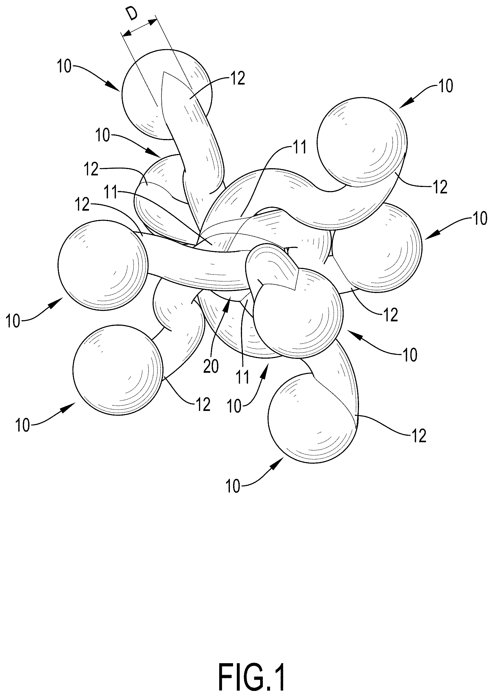
[0008] FIG. 1 is a perspective view of a first embodiment of a laminated structure with an adjustable elastic modulus in accordance with the present invention;
[0009] FIG. 2 is a front view of the laminated structure with an adjustable elastic modulus in FIG. 1;
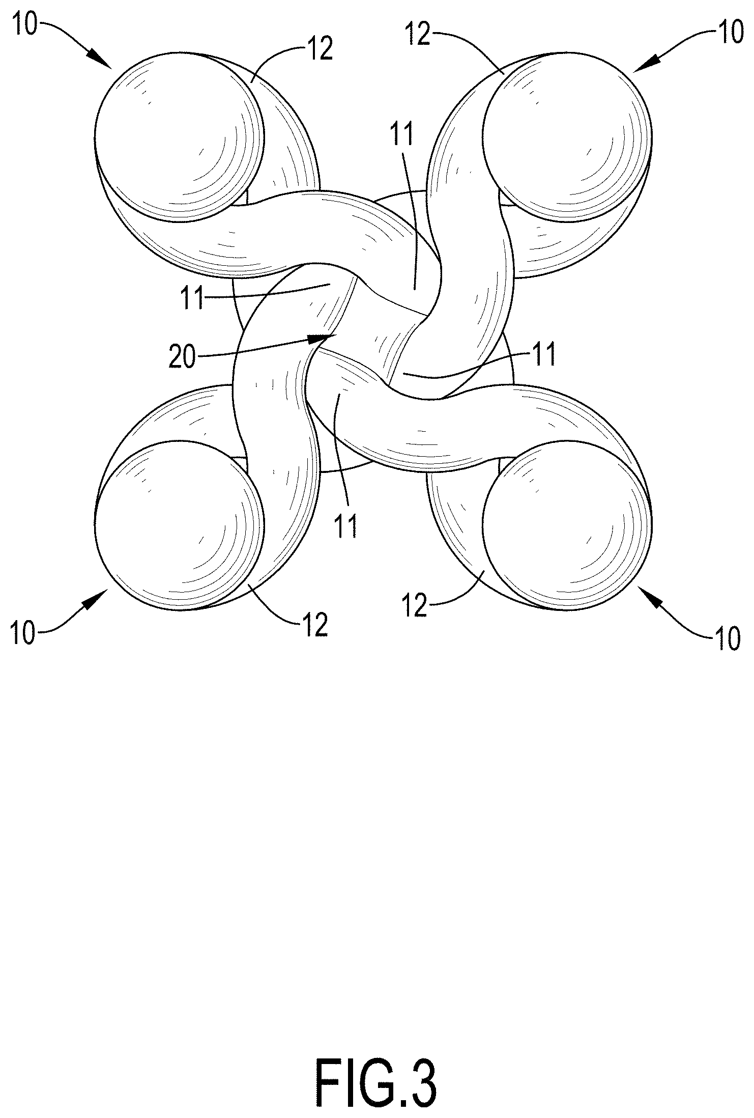
[0010] FIG. 3 is a top view of the laminated structure with an adjustable elastic modulus in FIG. 1;
[0011] FIG. 4 is another perspective view of the laminated structure with an adjustable elastic modulus in FIG. 1;
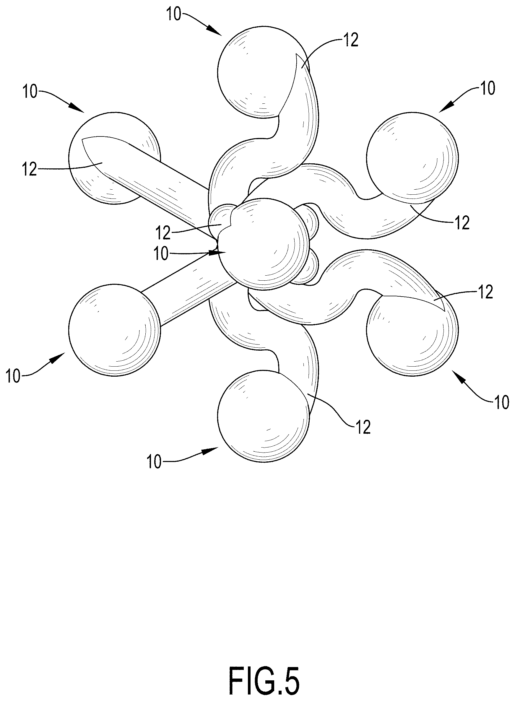
[0012] FIG. 5 is another perspective view of the laminated structure with an adjustable elastic modulus in FIG. 1;
[0013] FIG. 6 is an operational perspective view of the laminated structure with an adjustable elastic modulus in FIG. 1;
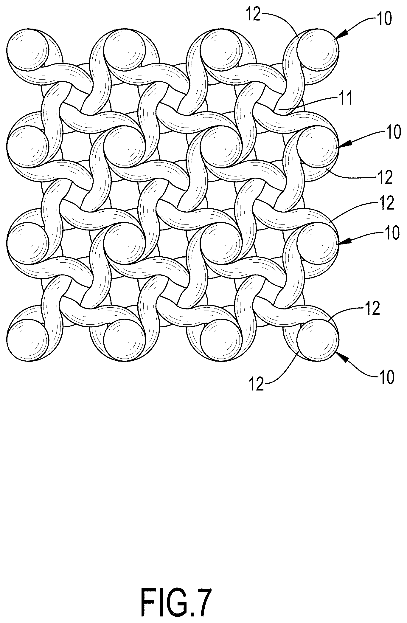
[0014] FIG. 7 is an operational front view of the laminated structure with an adjustable elastic modulus in FIG. 1;
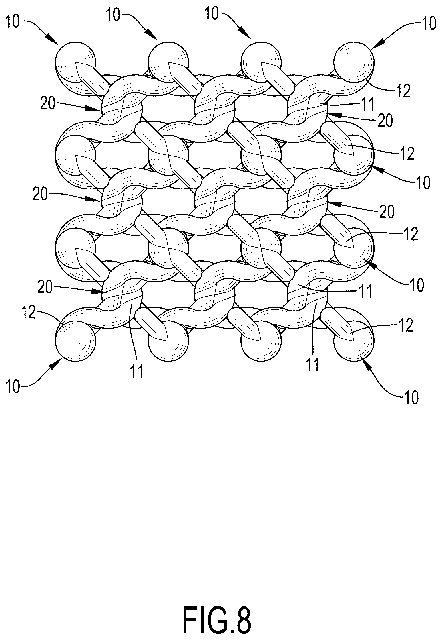
[0015] FIG. 8 is an operational top view of the laminated structure with an adjustable elastic modulus in FIG. 1;
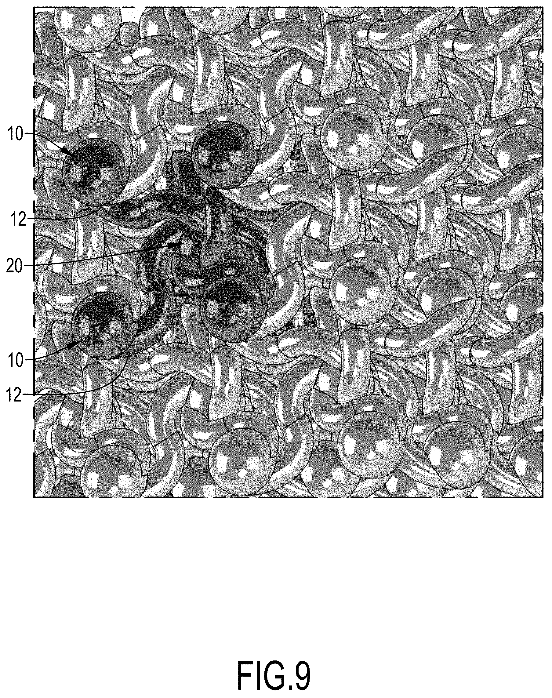
[0016] FIG. 9 is an enlarged operational perspective view of the laminated structure with an adjustable elastic modulus in FIG. 1;
[0017] FIG. 10 is an operational perspective view of the laminated structure with an adjustable elastic modulus in FIG. 1;
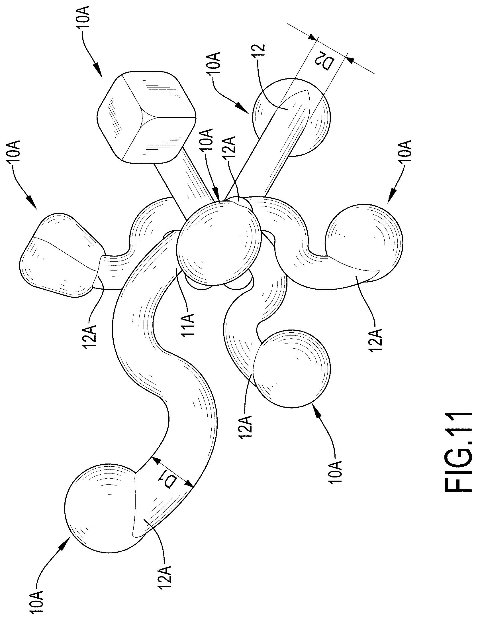
[0018] FIG. 11 is a perspective view of a second embodiment of a laminated structure with an adjustable elastic modulus in accordance with the present invention;
[0019] FIG. 12 is another perspective view of the laminated structure with an adjustable elastic modulus in FIG. 11;
[0020] FIG. 13 is another perspective view of the laminated structure with an adjustable elastic modulus in FIG. 11;
[0021] FIG. 14 is another perspective view of the laminated structure with an adjustable elastic modulus in FIG. 11;
[0022] FIG. 15 is another perspective view of the laminated structure with an adjustable elastic modulus in FIG. 11;
[0023] FIG. 16 is another perspective view of the laminated structure with an adjustable elastic modulus in FIG. 11; and
[0024] FIG. 17 is another perspective view of the laminated structure with an adjustable elastic modulus in FIG. 11.
DETAILED DESCRIPTION OF PREFERRED EMBODIMENT
[0025] With reference to FIGS. 1 to 5, a first embodiment of a laminated structure with an adjustable elastic modulus in accordance with the present invention comprises multiple connecting elements 10 and at least one connecting point 20.
[0026] Each connecting element 10 is an S-shaped curved component, and has an inner end 11 and an outer end 12. Preferably, in the first embodiment, the laminated structure comprises eight connecting elements 10. The eight connecting elements 10 are combined with each other by a connecting point 20. A spherical structure is formed at the outer end 12 of each connecting element 10. Furthermore, the diameter of each connecting element 10 ranges from 0.2 mm to 3 mm. In the first embodiment, the diameter of each connecting element 10 ranges from 0.23 mm to 0.9 mm. Furthermore, the connecting point 20 may be a sphere, an ellipsoid, a cuboid, a cube, or may be composed of surfaces of different shapes.
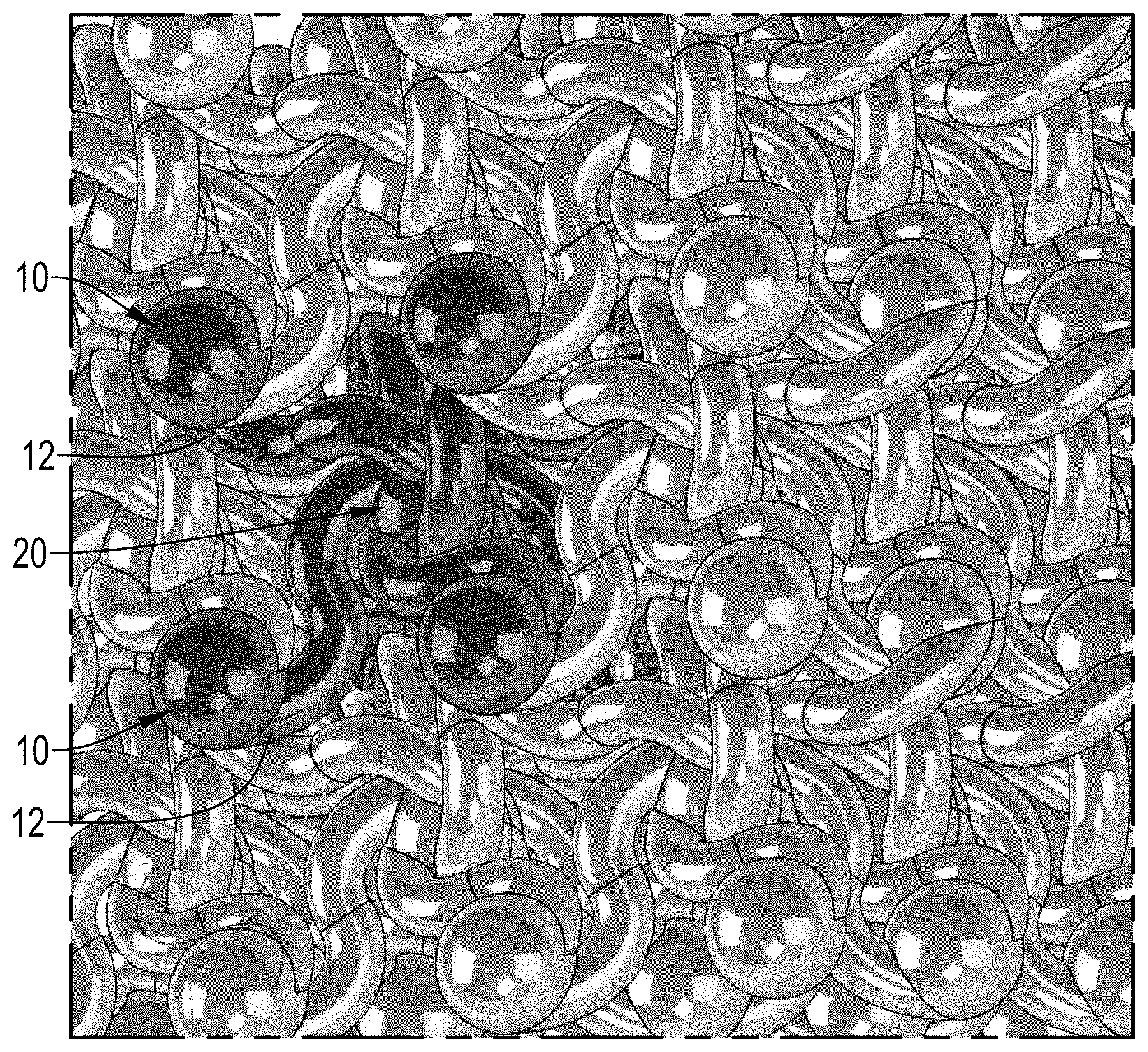
[0027] The first embodiment in accordance with the present invention is fabricated by powder-based 3D printing. With reference to FIGS. 6 to 10, when the first embodiment of the laminated structure with an adjustable elastic modulus in the present invention is in use, multiple connecting elements 10 are connected by at least one connecting point 20 to form a layered structure. The layered structure has a porous surface. The porous surface is specific to products made by powder-based 3D printing.
[0028] The structural strength of the laminated structure in accordance with the present invention is determined by the numbers of the connecting elements 10 and the at least one connecting point 20. Most of the time, one connecting point 20 is connected with 1 to 32 connecting elements 10. Preferably, in the first embodiment in accordance with the present invention, a connecting point 20 is connected with 1 to 16 connecting elements 10. The porosity and pore size of the laminated structure depend on the number of the connecting elements 10. Therefore, the elastic modulus of the first embodiment in accordance with the present invention is adjustable. The elastic modulus of the laminated structure in accordance with the present invention can be adjusted by adjusting the curvatures, the number of the curves at the same connection point, the diameter of the curve, the angle of the curve at the same point of intersection, etc.
[0029] With reference to FIGS. 6 to 10, when the laminated structure with an adjustable elastic modulus in accordance with the present invention is in use, the laminated structure is mounted in a human body. The muscle and blood of the human body would fill the pores of the laminated structure. In addition, the curvature of each connecting element 10 can be individually adjusted to form different elastic moduli. For instance, the connecting elements 10 at different positions have different curvatures to meet the individual needs of patients. Furthermore, the multiple connecting elements 10 can be combined with each other at different angles to meet the different requirements of tensile strength and compressive strength of different parts in different directions.
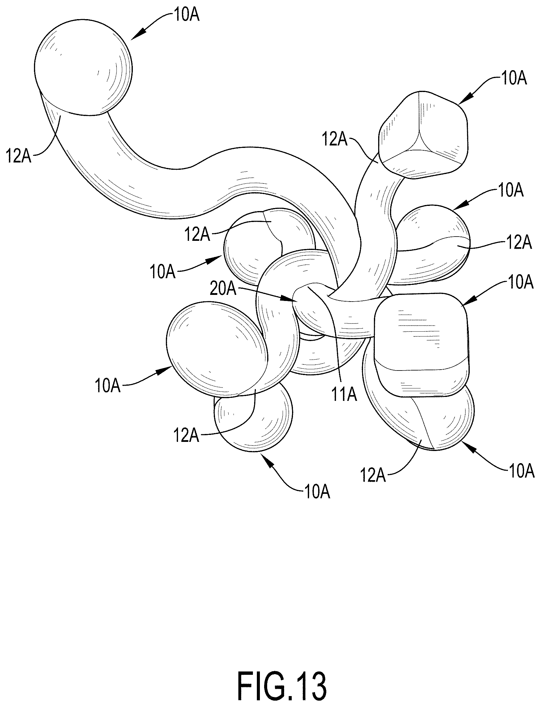
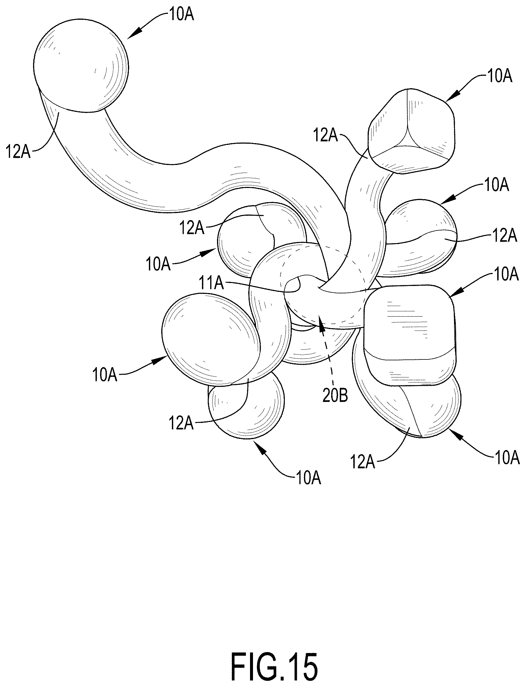
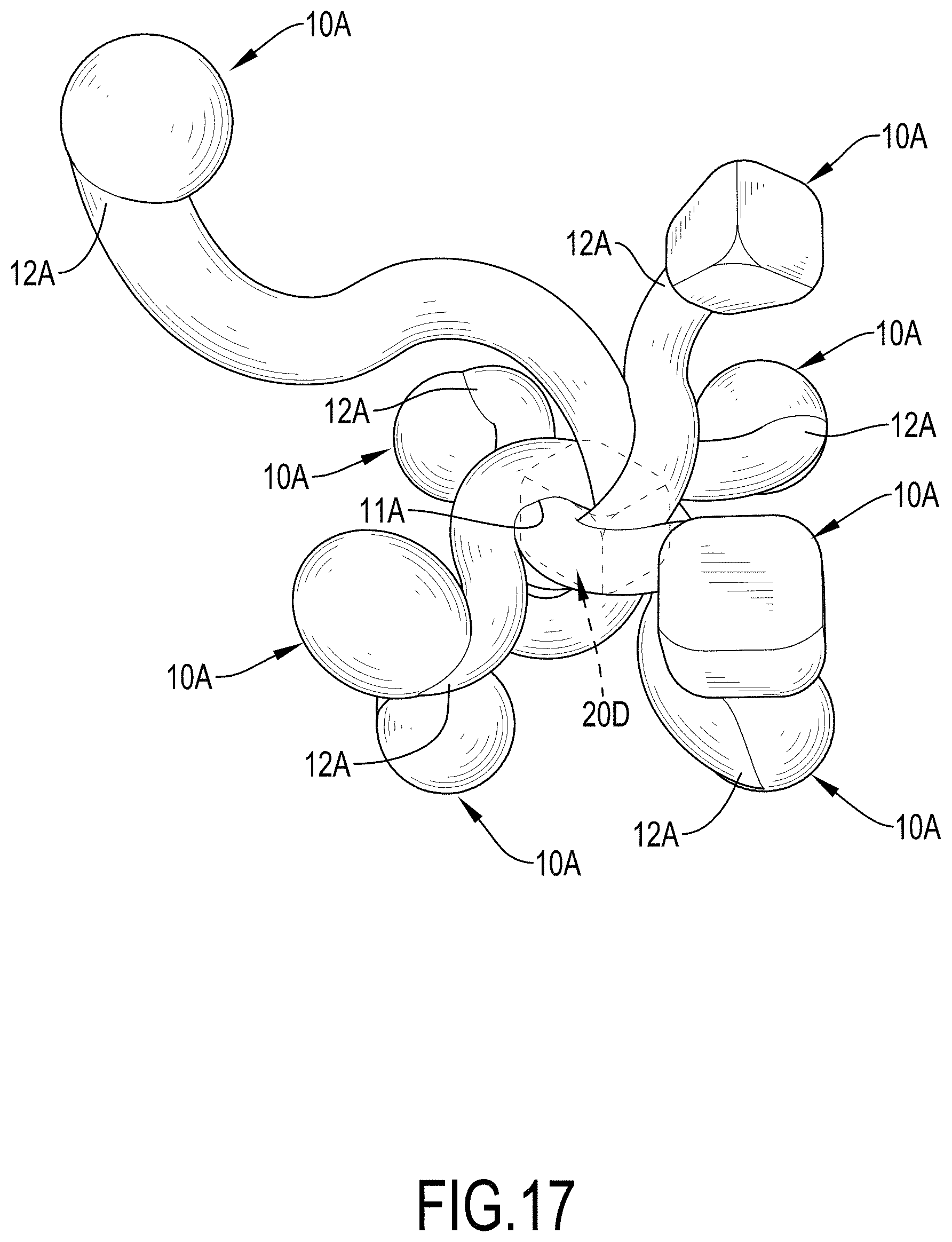
[0030] With reference to FIGS. 11 to 13, a second embodiment of a laminated structure with an adjustable elastic modulus in accordance with the present invention is substantially the same as the first embodiment except for the following features. The diameters of the connecting elements 10 are different from each other, and the curvatures of the connecting elements 10 are different from each other. Furthermore, a sphere, an ellipsoid, a cuboid, a cube, or multiple surfaces of different shapes may be formed at the outer end 12 of each connecting element 10.
[0031] Furthermore, with reference to FIG. 14, the connecting point 20A is a sphere. With reference to FIG. 15, the connecting point 20B is an ellipsoid. With reference to FIG. 16, the connecting point 20C is a cube. With reference to FIG. 17, the connecting point 20D is a cuboid.
[0032] Even though numerous characteristics and advantages of the present invention have been set forth in the foregoing description, together with details of the structure and function of the invention, the disclosure is illustrative only, and changes may be made in detail, especially in matters of shape, size, and arrangement of parts within the principles of the invention to the full extent indicated by the broad general meaning of the terms in which the appended claims are expressed.
* * * * *
D00000
D00001
D00002
D00003
D00004
D00005
D00006
D00007
D00008
D00009
D00010
D00011
D00012

D00013
D00014

D00015
D00016

D00017
XML
uspto.report is an independent third-party trademark research tool that is not affiliated, endorsed, or sponsored by the United States Patent and Trademark Office (USPTO) or any other governmental organization. The information provided by uspto.report is based on publicly available data at the time of writing and is intended for informational purposes only.
While we strive to provide accurate and up-to-date information, we do not guarantee the accuracy, completeness, reliability, or suitability of the information displayed on this site. The use of this site is at your own risk. Any reliance you place on such information is therefore strictly at your own risk.
All official trademark data, including owner information, should be verified by visiting the official USPTO website at www.uspto.gov. This site is not intended to replace professional legal advice and should not be used as a substitute for consulting with a legal professional who is knowledgeable about trademark law.