Ultrasonic Transducer For Surgical Instrument
Messerly; Jeffrey D. ; et al.
U.S. patent application number 16/527647 was filed with the patent office on 2019-11-21 for ultrasonic transducer for surgical instrument. The applicant listed for this patent is Ethicon LLC. Invention is credited to Jeffrey L. Aldridge, Brian D. Black, William E. Clem, Frederick Estera, Kevin L. Houser, Stephen M. Leuck, Jeffrey D. Messerly, Jerome R. Morgan, William A. Olson, Foster B. Stulen.
| Application Number | 20190350615 16/527647 |
| Document ID | / |
| Family ID | 61240171 |
| Filed Date | 2019-11-21 |


View All Diagrams
| United States Patent Application | 20190350615 |
| Kind Code | A1 |
| Messerly; Jeffrey D. ; et al. | November 21, 2019 |
ULTRASONIC TRANSDUCER FOR SURGICAL INSTRUMENT
Abstract
An ultrasonic surgical device is disclosed including a surgical tool including a proximal transducer mounting portion defining a surface, a distal end effector end, and a waveguide disposed therebetween, the waveguide extending along a longitudinal axis. The ultrasonic surgical device further includes a transducer is in mechanical communication with the surface of the transducer mounting portion. The transducer is configured to operate in a D31 mode with respect to the longitudinal axis of the waveguide. Upon activation by an electrical signal having a predetermined frequency component, the transducer is configured to induce a standing wave in the surgical tool to cause the end effector to vibrate, the standing wave having a wavelength proportional to the predetermined frequency component of the electrical signal
| Inventors: | Messerly; Jeffrey D.; (Cincinnati, OH) ; Black; Brian D.; (Loveland, OH) ; Olson; William A.; (Lebanon, OH) ; Stulen; Foster B.; (Mason, OH) ; Estera; Frederick; (Cincinnati, OH) ; Clem; William E.; (Bozeman, MT) ; Morgan; Jerome R.; (Cincinnati, OH) ; Aldridge; Jeffrey L.; (Lebanon, OH) ; Leuck; Stephen M.; (Milford, OH) ; Houser; Kevin L.; (Springboro, OH) | ||||||||||
| Applicant: |
|
||||||||||
|---|---|---|---|---|---|---|---|---|---|---|---|
| Family ID: | 61240171 | ||||||||||
| Appl. No.: | 16/527647 | ||||||||||
| Filed: | July 31, 2019 |
Related U.S. Patent Documents
| Application Number | Filing Date | Patent Number | ||
|---|---|---|---|---|
| 15679948 | Aug 17, 2017 | 10420580 | ||
| 16527647 | ||||
| 62379550 | Aug 25, 2016 | |||
| Current U.S. Class: | 1/1 |
| Current CPC Class: | H01L 41/0536 20130101; A61B 2017/294 20130101; A61B 17/00234 20130101; H01L 41/083 20130101; A61B 2017/320089 20170801; A61B 2018/00589 20130101; A61B 2018/00565 20130101; A61B 2017/00526 20130101; A61B 2017/0088 20130101; B29L 2031/7546 20130101; B29C 65/4805 20130101; A61B 2017/00477 20130101; A61B 2017/00402 20130101; A61B 17/1628 20130101; A61B 17/320068 20130101; A61B 2017/320088 20130101; A61B 2017/00017 20130101; A61B 2017/22027 20130101; H01L 41/0986 20130101; A61B 2018/00595 20130101; H01L 41/0835 20130101; A61B 2017/320074 20170801; A61B 2017/32007 20170801; A61B 2017/320098 20170801; A61B 2017/320082 20170801; A61N 7/02 20130101 |
| International Class: | A61B 17/32 20060101 A61B017/32; B29C 65/48 20060101 B29C065/48; A61B 17/00 20060101 A61B017/00; A61N 7/02 20060101 A61N007/02; H01L 41/083 20060101 H01L041/083; H01L 41/053 20060101 H01L041/053; H01L 41/09 20060101 H01L041/09 |
Claims
1. An ultrasonic surgical device comprising: a surgical tool comprising a proximal transducer mounting portion defining a surface, a distal end effector end, and a waveguide disposed therebetween, the waveguide extending along a longitudinal axis; and a transducer in mechanical communication with the surface of the transducer mounting portion; wherein the transducer is configured to operate in a D31 mode with respect to the longitudinal axis of the waveguide; and wherein, upon activation by an electrical signal having a predetermined frequency component, the transducer is configured to induce a standing wave in the surgical tool to cause the end effector to vibrate, the standing wave having a wavelength proportional to the predetermined frequency component of the electrical signal.
2. The ultrasonic surgical device of claim 1, wherein the surgical tool defines a lumen extending along the longitudinal axis.
3. The ultrasonic surgical device of claim 1, wherein the proximal transducer mounting portion comprises a cylindrical prism.
4. The ultrasonic surgical device of claim 3, wherein the transducer defines a hollow cylindrical portion in mechanical communication with the proximal transducer mounting portion.
5. The ultrasonic surgical device of claim 3, wherein the transducer comprises a plurality of partial cylindrical plates and wherein each of the plurality of partial cylindrical plates is in mechanical communication with the proximal transducer mounting portion.
6. The ultrasonic surgical device of claim 3, wherein the transducer mounting portion further comprises a flat surface in the cylindrical prism and wherein the transducer is in mechanical communication with the flat surface.
7. The ultrasonic surgical device of claim 1, wherein the proximal transducer mounting portion comprises a prism having a plurality of flat surfaces.
8. The ultrasonic surgical device of claim 7, wherein the transducer comprises a plurality of plates; wherein each of the plurality of plates is in mechanical communication with one of the plurality of flat surfaces; and wherein each of the plurality of plates is independently actuatable by an electrical signal having a predetermined frequency component.
Description
PRIORITY
[0001] This application is a divisional application claiming priority under 35 U.S.C. .sctn. 121 to U.S. patent application Ser. No. 15/679,948, entitled ULTRASONIC TRANSDUCER FOR SURGICAL INSTRUMENT, filed Aug. 17, 2017, now U.S. Patent Application Publication No. 2018/0055530, which claims the benefit of priority under 35 U.S.C. .sctn. 119(e) to U.S. Provisional Patent Application Ser. No. 62/379,550, entitled ULTRASONIC TRANSDUCER FOR SURGICAL INSTRUMENT, filed Aug. 25, 2016, the entire disclosures of which are hereby incorporated by reference herein.
BACKGROUND
[0002] The present disclosure relates, in general, to ultrasonic surgical instruments and more particularly to ultrasonic transducers to drive ultrasonic blades. Ultrasonic instruments, including both hollow core and solid core instruments, are used for the safe and effective treatment of many medical conditions. Ultrasonic instruments, and particularly solid core ultrasonic instruments, are advantageous because they may be used to cut and/or coagulate organic tissue using energy in the form of mechanical vibrations transmitted to a surgical end effector at ultrasonic frequencies. Ultrasonic vibrations, when transmitted to organic tissue at suitable energy levels and using a suitable end effector, may be used to cut, dissect, elevate or cauterize tissue or to separate muscle tissue from bone. Ultrasonic instruments utilizing solid core technology are particularly advantageous because of the amount of ultrasonic energy that may be transmitted from the ultrasonic transducer, through a waveguide, and to the surgical end effector. Such instruments may be used for open procedures or minimally invasive procedures, such as endoscopic or laparoscopic procedures, wherein the end effector is passed through a trocar to reach the surgical site.
[0003] Activating or exciting the end effector (e.g., cutting blade) of such instruments at ultrasonic frequencies induces longitudinal vibratory movement that generates localized heat within adjacent tissue. Because of the nature of ultrasonic instruments, a particular ultrasonically actuated end effector may be designed to perform numerous functions, including, for example, cutting and coagulation. Ultrasonic vibration is induced in the surgical end effector by electrically exciting a transducer, for example. The transducer may be constructed of one or more piezoelectric or magnetostrictive elements in the instrument hand piece. Vibrations generated by the transducer are transmitted to the surgical end effector via an ultrasonic waveguide extending from the transducer to the surgical end effector. The waveguide and end effector are designed to resonate at the same frequency as the transducer. Therefore, when an end effector is attached to a transducer, the overall system frequency is the same frequency as the transducer itself.
[0004] The amplitude of the longitudinal ultrasonic vibration at the tip, d, of the end effector behaves as a simple sinusoid at the resonant frequency as given by:
d=A sin(.omega.t)
where:
[0005] .omega.=the radian frequency which equals 2.pi.times the cyclic frequency, f; and
[0006] A=the zero-to-peak amplitude.
The longitudinal excursion of the end effector tip is defined as the peak-to-peak (p-t-p) amplitude, which is just twice the amplitude of the sine wave or 2A. Often, the end effector can comprise a blade which, owing to the longitudinal excursion, can cut and/or coagulate tissue. U.S. Pat. No. 6,283,981, which issued on Sep. 4, 2001 and is entitled METHOD OF BALANCING ASYMMETRIC ULTRASONIC SURGICAL BLADES; U.S. Pat. No. 6,309,400, which issued on Oct. 30, 2001 and is entitled CURVED ULTRASONIC BLADE HAVING A TRAPEZOIDAL CROSS SECTION; and U.S. Pat. No. 6,436,115, which issued on Aug. 20, 2002 and is entitled BALANCED ULTRASONIC BLADE INCLUDING A PLURALITY OF BALANCE ASYMMETRIES, the entire disclosures of which are hereby incorporated by reference herein, disclose various ultrasonic surgical instruments.
SUMMARY
[0007] In one general aspect, various aspects are directed to an ultrasonic surgical instrument that comprises a transducer configured to produce vibrations along a longitudinal axis of a surgical tool at a predetermined frequency. In various aspects, the surgical tool may include an ultrasonic blade extends along the longitudinal axis and is coupled to the transducer. In various aspects, the surgical tool includes a body having a proximal end and a distal end, wherein the distal end is movable relative to the longitudinal axis by the vibrations produced by the transducer, and the proximal end is mechanically coupled to the transducer.
[0008] In one aspect, the present disclosure provides an ultrasonic medical device comprising a surgical tool comprising a transducer mounting portion (e.g., a transducer base plate) at a proximal end, an end effector at a distal end, and a waveguide disposed therebetween, the waveguide extending along a longitudinal axis, the transducer mounting portion of the surgical tool comprising a first face and a second face at the proximal end, the second face positioned opposite the first face; a first transducer comprising a body defining a face; and a second transducer comprising a body defining a face; wherein the face of the first transducer is in mechanical communication with the first face of the surgical tool and the face of the second transducer is in mechanical communication with the second face of the surgical tool opposite the first transducer; wherein the first transducer and the second transducer are configured to operate in a D31 mode with respect to the longitudinal axis of the waveguide; wherein, upon activation by an electrical signal having a predetermined frequency component, the first and second transducers are configured to induce a standing wave in the surgical tool to cause the end effector to vibrate, the standing wave having a wavelength proportional to the predetermined frequency component of the electrical signal; and wherein the surgical tool defines nodes and antinodes corresponding to the nodes and antinodes of the induced standing wave, wherein the nodes correspond to locations of minimal displacement and the antinodes correspond to locations of maximum displacement.
[0009] In another aspect, the present disclosure provides an ultrasonic surgical device comprising a surgical tool comprising a proximal transducer mounting portion defining a surface, a distal end effector end, and a waveguide disposed therebetween, the waveguide extending along a longitudinal axis; and a transducer in mechanical communication with the surface of the transducer mounting portion; wherein the transducer is configured to operate in a D31 mode with respect to the longitudinal axis of the waveguide; and wherein, upon activation by an electrical signal having a predetermined frequency component, the transducer is configured to induce a standing wave in the surgical tool to cause the end effector to vibrate, the standing wave having a wavelength proportional to the predetermined frequency component of the electrical signal.
[0010] In another aspect, the present disclosure provides an ultrasonic medical device comprising: a surgical tool comprising a transducer mounting portion at a proximal end, an end effector at a distal end, and a waveguide disposed therebetween, the waveguide extending along a longitudinal axis, the transducer mounting portion of the surgical tool comprising a first face and a second face at the proximal end, the second face positioned opposite the first face; a first transducer comprising a body defining a face; and a second transducer comprising a body defining a face; a third transducer comprising a body defining a face; and a fourth transducer comprising a body defining a face; wherein the face of the first transducer is in mechanical communication with the first face of the surgical tool and the face of the second transducer is in mechanical communication with the second face of the surgical tool opposite the first transducer; wherein the first transducer and the second transducer are configured to operate in a D31 mode with respect to the longitudinal axis of the waveguide; wherein, upon activation by an electrical signal having a predetermined frequency component, the first and second transducers are configured to induce a standing wave in the surgical tool to cause the end effector to vibrate, the standing wave having a wavelength proportional to the predetermined frequency component of the electrical signal; and wherein the surgical tool defines nodes and antinodes corresponding to the nodes and antinodes of the induced standing wave, wherein the nodes correspond to locations of minimal displacement and the antinodes correspond to locations of maximum displacement.
FIGURES
[0011] The features of various aspects are set forth with particularity in the appended claims. The various aspects, however, both as to organization and methods of operation, together with further objects and advantages thereof, may best be understood by reference to the following description, taken in conjunction with the accompanying drawings as follows.
[0012] FIG. 1 illustrates an ultrasonic surgical instrument system, according to one aspect of this disclosure.
[0013] FIGS. 2A-2C illustrate a piezoelectric transducer, according to one aspect of this disclosure.
[0014] FIG. 3 illustrates a D31 ultrasonic transducer architecture that includes an ultrasonic waveguide and one or more piezoelectric elements fixed to the ultrasonic waveguide, according to one aspect of this disclosure.
[0015] FIG. 4A is another perspective view of an ultrasonic medical device having a single pair of piezoelectric transducers, according to one aspect of this disclosure.
[0016] FIG. 4B is a perspective view of a transducer mounting portion of an ultrasonic medical device depicted in FIG. 4A, according to one aspect of this disclosure.
[0017] FIG. 5 is a plan view of a transducer mounting portion of an ultrasonic medical device depicted in FIG. 4A, according to one aspect of this disclosure.
[0018] FIGS. 6-9 are perspective views of a transducer mounting portion of an ultrasonic medical device having multiple pairs of piezoelectric transducers, according to one aspect of this disclosure.
[0019] FIGS. 10 and 11 are perspective views of a transducer mounting portion of an ultrasonic medical device having a pair of piezoelectric transducers imbedded in a surgical tool, according to one aspect of this disclosure.
[0020] FIGS. 12 and 13 are perspective views of a transducer mounting portion of an ultrasonic medical device having a pair of piezoelectric transducers held by one or more securing clips, according to one aspect of this disclosure.
[0021] FIG. 14 is a perspective view of a transducer mounting portion of an ultrasonic medical device including mounting flanges, according to one aspect of this disclosure.
[0022] FIG. 15 is a perspective view of a transducer mounting portion of the ultrasonic medical device of FIG. 14 mounted in a housing, according to one aspect of this disclosure.
[0023] FIG. 16 is a side view the transducer mounting portion of the ultrasonic medical device of FIG. 1 mounted in a housing, according to one aspect of this disclosure, according to one aspect of this disclosure.
[0024] FIGS. 17 and 18 are plan views of an ultrasonic medical device having a transducer mounting portion having a form of a square or rectangular prism, according to one aspect of this disclosure.
[0025] FIG. 19 is a cross-sectional view of an ultrasonic medical device fabricated from square stock, according to one aspect of this disclosure.
[0026] FIG. 20 is a cross-sectional view of an ultrasonic medical device fabricated from round stock, according to one aspect of this disclosure.
[0027] FIG. 21 is a perspective view of an ultrasonic medical device having a transducer mounting portion having a form of a triangular prism, according to one aspect of this disclosure.
[0028] FIGS. 22-25 are cross-sectional views of a transducer mounting portion of an ultrasonic medical device in which the transducer mounting portion has a form of a triangular prism, according to one aspect of this disclosure.
[0029] FIGS. 26-28 are perspective views of an ultrasonic medical device fabricated from round stock, according to one aspect of this disclosure.
[0030] FIG. 29 is a cross-sectional view of the transducer mounting portion of the ultrasonic medical device of FIG. 28, according to one aspect of this disclosure.
[0031] FIG. 30 is a side view of an ultrasonic medical device fabricated from round stock, according to one aspect of this disclosure.
[0032] FIG. 31 is a cross-sectional view of the transducer mounting portion of the ultrasonic medical device of FIG. 30, according to one aspect of this disclosure.
[0033] FIG. 32 is a perspective view of surgical tools for an ultrasonic medical device, according to one aspect of this disclosure.
[0034] FIG. 33 is a perspective view of an end effector of a surgical tools depicted in FIG. 32, according to one aspect of this disclosure.
[0035] FIG. 34 is a perspective view of an ultrasonic medical device incorporating a surgical tool depicted in FIG. 32, according to one aspect of this disclosure.
[0036] FIG. 35 is a perspective view of an ultrasonic medical device incorporating a surgical tool depicted in FIG. 32, according to one aspect of this disclosure.
[0037] FIG. 36 is a perspective view of surgical tools during a fabrication step from flat stock, according to one aspect of this disclosure.
[0038] FIG. 37 is a plan view of surgical tools depicting the metal grain orientation of the surgical tools, according to one aspect of this disclosure.
[0039] FIG. 38 is a perspective view of the surgical tools depicted in FIG. 37, according to one aspect of this disclosure.
[0040] FIG. 39 is a perspective view of additional surgical tools depicted in FIG. 37, according to one aspect of this disclosure.
[0041] FIG. 40 is a side view of an additional fabrication step of a surgical tool, according to one aspect of this disclosure.
[0042] FIG. 41 is a plan view of the surgical tool depicted in FIG. 32 with a superimposed illustration of a mechanical standing wave imparted to it by an activated piezoelectric transducer, according to one aspect of this disclosure.
[0043] FIG. 42 is a side view of the surgical tool depicted in FIG. 41, according to one aspect of this disclosure.
[0044] FIG. 43 is a plan view of a surgical tool configured to be displaced in a side-way manner, according to one aspect of this disclosure.
[0045] FIGS. 44 and 45 illustrate hand actuated ultrasonic medical devices, according to one aspect of this disclosure.
[0046] FIG. 46 illustrates the effector end of the hand actuated ultrasonic medical device of FIG. 45, according to one aspect of this disclosure.
[0047] FIG. 47 illustrates a plan view of two surgical tools having female threads machined in the transducer mounting portion, according to one aspect of this disclosure.
[0048] FIG. 48 is a perspective view of a transducer mounting portion of the surgical tool of FIG. 47 mounted in an ultrasonic medical device, according to one aspect of this disclosure.
[0049] FIGS. 49 and 50 are a side view and a perspective view, respectively, of the two surgical tools of FIG. 47 mounted in the ultrasonic medical device of FIG. 48, according to one aspect of this disclosure.
[0050] FIG. 51 is an end perspective view of the surgical device of FIG. 47, illustrating the female threads tapped into the transducer mounting portion, according to one aspect of this disclosure.
[0051] FIG. 52 is a plan view of fabricating female threads into the transducer mounting portion of the surgical tool of FIG. 47, according to one aspect of this disclosure.
[0052] FIG. 53 is a plan view of the female threads tapped into the transducer mounting portion of the surgical tool of FIG. 47, according to one aspect of this disclosure.
[0053] FIG. 54 is a perspective view of a surgical tool including a threaded stub at the transducer mounting portion, according to one aspect of this disclosure.
[0054] FIG. 55 is a close-up perspective view of the transducer mounting portion of the surgical tool of FIG. 54, according to one aspect of this disclosure.
[0055] FIG. 56 is a close-up perspective view of the transducer mounting portion of a surgical tool including a threaded stub, according to one aspect of this disclosure.
[0056] FIG. 57 is a close-up perspective view of the transducer mounting portion of a surgical tool including a threaded stub and chamfers, according to one aspect of this disclosure.
[0057] FIG. 58 is a perspective view of a surgical tool having a flat blade with a straight tip, according to one aspect of this disclosure.
[0058] FIG. 59 is a perspective view of a surgical tool having a twisted flat blade with a curved and tapered tip, according to one aspect of this disclosure.
[0059] FIGS. 60-62 are plan views of surgical tools having blades with complex features, according to one aspect of this disclosure.
[0060] FIG. 63 is a perspective view of a surgical tool having a blade with a curved tip of large curvature, according to one aspect of this disclosure.
[0061] FIG. 64 is a plan view of surgical tools having blades with curved tips, according to one aspect of this disclosure.
[0062] FIG. 65 is a perspective view of a surgical tool having a transducer mounting portion with a wide and flat surface, according to one aspect of this disclosure.
[0063] FIG. 66 is a plan view of a surgical tool having a transducer mounting portion with a wide and flat surface, according to one aspect of this disclosure.
DESCRIPTION
[0064] Applicant of the present application owns the following patent applications filed on Aug. 17, 2017 and which are each herein incorporated by reference in their respective entireties:
[0065] U.S. patent application Ser. No. 15/679,940, entitled ULTRASONIC TRANSDUCER TECHNIQUES FOR ULTRASONIC SURGICAL INSTRUMENT by inventors Jeffrey Messerly et al. filed Aug. 17, 2017.
[0066] U.S. patent application Ser. No. 15/679,952, ENTITLED ELECTRICAL AND THERMAL CONNECTIONS FOR ULTRASONIC TRANSDUCER by inventors Jeffrey Messerly et al. filed Aug. 17, 2017.
[0067] U.S. patent application Ser. No. 15/679,959, entitled ULTRASONIC TRANSDUCER TO WAVEGUIDE ACOUSTIC COUPLING, CONNECTIONS, AND CONFIGURATIONS by inventors Jeffrey Messerly et al. filed Aug. 17, 2017.
[0068] U.S. patent application Ser. No. 15/679,960, entitled ULTRASONIC TRANSDUCER TO WAVEGUIDE JOINING by inventors Jeffrey Messerly et al. filed Aug. 17, 2017.
[0069] U.S. patent application Ser. No. 15/679,967, entitled TISSUE LOADING OF A SURGICAL INSTRUMENT by inventors Jeffrey Messerly et al. filed Aug. 17, 2017.
[0070] Before explaining various aspects in detail, it should be noted that such aspects are not limited in their application or use to the details of construction and arrangement of parts illustrated in the accompanying drawings and description. The illustrative aspects may be implemented or incorporated in other aspects, variations and modifications, and may be practiced or carried out in various ways. For example, the surgical instruments disclosed below are illustrative only and not meant to limit the scope or application thereof. Furthermore, unless otherwise indicated, the terms and expressions employed herein have been chosen for the purpose of describing the illustrative aspects for the convenience of the reader and are not to limit the scope thereof.
[0071] Certain exemplary aspects will now be described to provide an overall understanding of the principles of the structure, function, manufacture, and use of the devices and methods disclosed herein. One or more examples of these aspects are illustrated in the accompanying drawings. Those of ordinary skill in the art will understand that the devices and methods specifically described herein and illustrated in the accompanying drawings are non-limiting exemplary aspects and that the scope of the various aspects is defined solely by the claims. The features illustrated or described in connection with one exemplary aspect may be combined with the features of other aspects. Such modifications and variations are intended to be included within the scope of the claims.
[0072] Various aspects described herein relate, in general, to ultrasonic surgical instruments and blades for use therewith. Examples of ultrasonic surgical instruments and blades are disclosed in U.S. Pat. Nos. 5,322,055; 5,954,736; 6,309,400; 6,278,218; 6,283,981; 6,325,811; and 8,319,400, wherein the entire disclosures of which are incorporated by reference herein.
[0073] According to various aspects, an ultrasonic instrument comprising a surgical tool having an end effector such as a blade can yield a particular benefit or benefits in orthopedic procedures where it is desirable to remove cortical bone and/or tissue while controlling bleeding. Due to its cutting and coagulation characteristics, a blade of an ultrasonic surgical instrument may be useful for general soft tissue cutting and coagulation. In certain circumstances, a blade according to various aspects may be useful to simultaneously cut and hemostatically seal or cauterize tissue. A blade may be straight or curved, and useful for either open or laparoscopic applications. A blade according to various aspects may be useful in spine surgery, especially to assist in posterior access in removing muscle from bone.
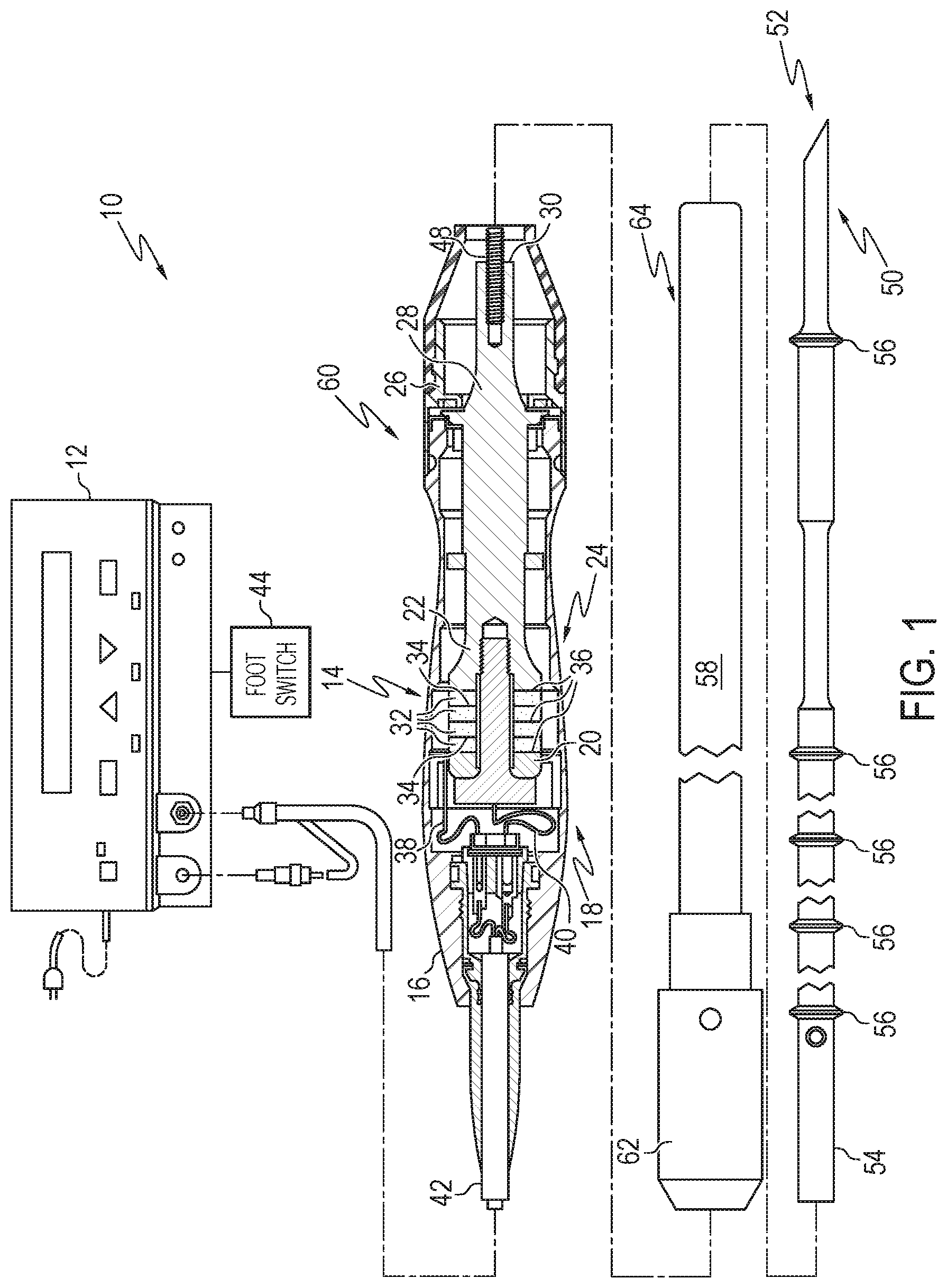
[0074] FIG. 1 illustrates one aspect of an ultrasonic system 10. One aspect of the ultrasonic system 10 comprises an ultrasonic signal generator 12 coupled to an ultrasonic transducer 14, a hand piece assembly 60 comprising a hand piece housing 16, and an end effector 50. The ultrasonic transducer 14, which is known as a "Langevin stack," generally includes a transduction portion 18, a first resonator or end-bell 20, and a second resonator or fore-bell 22, and ancillary components. In various aspects, the ultrasonic transducer 14 is preferably an integral number of one-half system wavelengths (n.lamda./2) in length as will be described in more detail below. An acoustic assembly 24 can include the ultrasonic transducer 14, a mount 26, a velocity transformer 28, and a surface 30.
[0075] It will be appreciated that the terms "proximal" and "distal" are used herein with reference to a clinician gripping the hand piece assembly 60. Thus, the end effector 50 is distal with respect to the more proximal hand piece assembly 60. It will be further appreciated that, for convenience and clarity, spatial terms such as "top" and "bottom" also are used herein with respect to the clinician gripping the hand piece assembly 60. However, surgical instruments are used in many orientations and positions, and these terms are not intended to be limiting and absolute.
[0076] The distal end of the end-bell 20 is connected to the proximal end of the transduction portion 18, and the proximal end of the fore-bell 22 is connected to the distal end of the transduction portion 18. The fore-bell 22 and the end-bell 20 have a length determined by a number of variables, including the thickness of the transduction portion 18, the density and modulus of elasticity of the material used to manufacture the end-bell 20 and the fore-bell 22, and the resonant frequency of the ultrasonic transducer 14. The fore-bell 22 may be tapered inwardly from its proximal end to its distal end to amplify the ultrasonic vibration amplitude of the velocity transformer 28, or, alternately, fore-bell 22 may have no tapering.
[0077] Referring again to FIG. 1, end-bell 20 can include a threaded member extending therefrom which can be configured to be threadably engaged with a threaded aperture in fore-bell 22. In various aspects, piezoelectric elements, such as piezoelectric elements 32, for example, can be compressed between end-bell 20 and fore-bell 22 when end-bell 20 and fore-bell 22 are assembled together. Piezoelectric elements 32 may be fabricated from any suitable material, such as, for example, lead zirconate-titanate, lead meta-niobate, lead titanate, and/or any suitable piezoelectric crystal material, for example.
[0078] In various aspects, as discussed in greater detail below, transducer 14 can further comprise electrodes, such as positive electrodes 34 and negative electrodes 36, for example, which can be configured to create a voltage potential across one or more piezoelectric elements 32. Each of the positive electrodes 34, negative electrodes 36, and the piezoelectric elements 32 can comprise a bore extending through the center which can be configured to receive the threaded member of end-bell 20. In various aspects, the positive and negative electrodes 34 and 36 are electrically coupled to wires 38 and 40, respectively, wherein the wires 38 and 40 can be encased within a cable 42 and electrically connectable to the ultrasonic signal generator 12 of the ultrasonic system 10.
[0079] In various aspects, the ultrasonic transducer 14 of the acoustic assembly 24 converts the electrical signal from the ultrasonic signal generator 12 into mechanical energy that results in primarily longitudinal vibratory motion of the ultrasonic transducer 24 and the end effector 50 at ultrasonic frequencies. A suitable generator is available as model number GEN11, from Ethicon Endo-Surgery, Inc., Cincinnati, Ohio. When the acoustic assembly 24 is energized, a vibratory motion standing wave is generated through the acoustic assembly 24. A suitable vibrational frequency range may be about 20 Hz to 120 kHz and a well-suited vibrational frequency range may be about 30-70 kHz and one example operational vibrational frequency may be approximately 55.5 kHz.
[0080] The amplitude of the vibratory motion at any point along the acoustic assembly 24 may depend upon the location along the acoustic assembly 24 at which the vibratory motion is measured. A minimum or zero crossing in the vibratory motion standing wave is generally referred to as a node (i.e., where motion is usually minimal), and an absolute value maximum or peak in the standing wave is generally referred to as an anti-node (i.e., where motion is usually maximal). The distance between an anti-node and its nearest node is one-quarter wavelength (.lamda./4).
[0081] As outlined above, the wires 38 and 40 transmit an electrical signal from the ultrasonic signal generator 12 to the positive electrodes 34 and the negative electrodes 36. The piezoelectric elements 32 are energized by the electrical signal supplied from the ultrasonic signal generator 12 in response to a foot switch 44, for example, to produce an acoustic standing wave in the acoustic assembly 24. The electrical signal causes disturbances in the piezoelectric elements 32 in the form of repeated small displacements resulting in large compression forces within the material. The repeated small displacements cause the piezoelectric elements 32 to expand and contract in a continuous manner along the axis of the voltage gradient, producing longitudinal waves of ultrasonic energy.
[0082] In various aspects, the ultrasonic energy produced by transducer 14 can be transmitted through the acoustic assembly 24 to the end effector 50 via an ultrasonic transmission waveguide 46. In order for the acoustic assembly 24 to deliver energy to the end effector 50, the components of the acoustic assembly 24 are acoustically coupled to the end effector 50. For example, the distal end of the ultrasonic transducer 14 may be acoustically coupled at the surface 30 to the proximal end of the ultrasonic transmission waveguide 46 by a threaded connection such as a stud 48.
[0083] The components of the acoustic assembly 24 can be acoustically tuned such that the length of any assembly is an integral number of one-half wavelengths (n.lamda./2), where the wavelength .DELTA. is the wavelength of a pre-selected or operating longitudinal vibration drive frequency f.sub.d of the acoustic assembly 24, and where n is any positive integer. It is also contemplated that the acoustic assembly 24 may incorporate any suitable arrangement of acoustic elements.
[0084] The ultrasonic end effector 50 may have a length substantially equal to an integral multiple of one-half system wavelengths (.lamda./2). A distal end 52 of the ultrasonic end effector 50 may be disposed at, or at least near, an antinode in order to provide the maximum, or at least nearly maximum, longitudinal excursion of the distal end. When the transducer assembly is energized, in various aspects, the distal end 52 of the ultrasonic end effector 50 may be configured to move in the range of, for example, approximately 10 to 500 microns peak-to-peak and preferably in the range of approximately 30 to 150 microns at a predetermined vibrational frequency.
[0085] As outlined above, the ultrasonic end effector 50 may be coupled to the ultrasonic transmission waveguide 46. In various aspects, the ultrasonic end effector 50 and the ultrasonic transmission guide 46 as illustrated are formed as a single unit construction from a material suitable for transmission of ultrasonic energy such as, for example, Ti6Al4V (an alloy of titanium including aluminum and vanadium), aluminum, stainless steel, and/or any other suitable material. Alternately, the ultrasonic end effector 50 may be separable (and of differing composition) from the ultrasonic transmission waveguide 46, and coupled by, for example, a stud, weld, glue, quick connect, or other suitable known methods. The ultrasonic transmission waveguide 46 may have a length substantially equal to an integral number of one-half system wavelengths (.lamda./2), for example. The ultrasonic transmission waveguide 46 may be preferably fabricated from a solid core shaft constructed out of material that propagates ultrasonic energy efficiently, such as titanium alloy (i.e., Ti6Al4V) or an aluminum alloy, for example.
[0086] In the aspect illustrated in FIG. 1, the ultrasonic transmission waveguide 46 comprises a proximal portion 54 and a plurality of stabilizing silicone rings or compliant supports 56 positioned at, or at least near, a plurality of nodes. The silicone rings 56 can dampen undesirable vibration and isolate the ultrasonic energy from a sheath 58 at least partially surrounding waveguide 46, thereby assuring the flow of ultrasonic energy in a longitudinal direction to the distal end 52 of the end effector 50 with maximum efficiency.
[0087] As shown in FIG. 1, the sheath 58 can be coupled to the distal end of the handpiece assembly 60. The sheath 58 generally includes an adapter or nose cone 62 and an elongated tubular member 64. The tubular member 64 is attached to and/or extends from the adapter 62 and has an opening extending longitudinally therethrough. In various aspects, the sheath 58 may be threaded or snapped onto the distal end of the housing 16. In at least one aspect, the ultrasonic transmission waveguide 46 extends through the opening of the tubular member 64 and the silicone rings 56 can contact the sidewalls of the opening and isolate the ultrasonic transmission waveguide 46 therein. In various aspects, the adapter 62 of the sheath 58 is preferably constructed from Ultem.RTM., for example, and the tubular member 64 is fabricated from stainless steel, for example. In at least one aspect, the ultrasonic transmission waveguide 46 may have polymeric material, for example, surrounding it in order to isolate it from outside contact.
[0088] As described above, a voltage, or power source can be operably coupled with one or more of the piezoelectric elements of a transducer, wherein a voltage potential applied to each of the piezoelectric elements can cause the piezoelectric elements to expand and contract, or vibrate, in a longitudinal direction. As also described above, the voltage potential can be cyclical and, in various aspects, the voltage potential can be cycled at a frequency which is the same as, or nearly the same as, the resonant frequency of the system of components comprising transducer 14, wave guide 46, and end effector 50, for example. In various aspects, however, certain of the piezoelectric elements within the transducer may contribute more to the standing wave of longitudinal vibrations than other piezoelectric elements within the transducer. More particularly, a longitudinal strain profile may develop within a transducer wherein the strain profile may control, or limit, the longitudinal displacements that some of the piezoelectric elements can contribute to the standing wave of vibrations, especially when the system is being vibrated at or near its resonant frequency.
[0089] It may be recognized, in reference to the ultrasonic surgical instrument system 10 of FIG. 1, that multiple components may be required to couple the mechanical vibrations from the piezoelectric elements 32 through the wave guide 46 to the end effector 50. The additional acoustic elements comprising the acoustic assembly 24 may add additional manufacturing costs, fabrication steps, and complexity to the system. Disclosed below are aspects of an ultrasonic medical device that may require fewer components, manufacturing steps, and costs than the equivalent device illustrated in FIG. 1 and as disclosed above.
[0090] Again, referring to FIG. 1, the piezoelectric elements 32 are configured into a "Langevin" stack, in which the piezoelectric elements 32 and their activating electrodes 34 and 36 (together, transducer 14) are interleaved. The mechanical vibrations of the activated piezoelectric elements 32 propagate along the longitudinal axis of the transducer 14, and are coupled via the acoustic assembly 24 to the end of the waveguide 46. Such a mode of operation of a piezoelectric element is frequently described as the D33 mode of the element, especially for ceramic piezoelectric elements comprising, for example, lead zirconate-titanate, lead meta-niobate, or lead titanate. The D33 mode of operation of a ceramic piezoelectric element is illustrated in FIGS. 2A-2C.
[0091] FIG. 2A depicts an exemplary piezoelectric element 200 fabricated from a ceramic piezoelectric material. A piezoelectric ceramic material is a polycrystalline material comprising a plurality of individual microcrystalline domains. Each microcrystalline domain possesses a polarization axis along which the domain may expand or contract in response to an imposed electric field. However, in a native ceramic, the polarization axes of the microcrystalline domains are arranged randomly, so there is no net piezoelectric effect in the bulk ceramic. A net re-orientation of the polarization axes may be induced by subjecting the ceramic to a temperature above the Currie temperature of the material and placing the material in a strong electrical field. Once the temperature of the sample is dropped below the Currie temperature, a majority of the individual polarization axes will be re-oriented and fixed in a bulk polarization direction. FIG. 2A illustrates such a piezoelectric element 200 after being polarized along the inducing electric field axis P. While the un-polarized piezoelectric element 200 lacks any net piezoelectric axis, the polarized element 200 can be described as possessing a polarization axis, d3, parallel to the inducing field axis P direction. For completeness, an axis orthogonal to the d3 axis may be termed a d1 axis. The dimensions of the piezoelectric element 200 are labeled as length (L), width (W), and thickness (T).
[0092] FIGS. 2B and 2C illustrate the mechanical deformations of a piezoelectric element 200 that may be induced by subjecting the piezoelectric element 200 to an actuating electrical field E oriented along the d3 (or P) axis. FIG. 2B illustrates the effect of an electric field E having the same direction as the polarization field P along the d3 axis on a piezoelectric element 205. As illustrated in FIG. 2B, the piezoelectric element 205 may deform by expanding along the d3 axis while compressing along the d1 axis. FIG. 2C illustrates the effect of an electric field E having the opposing direction to the polarization field P along the d3 axis on a piezoelectric element 210. As illustrated in FIG. 2C, the piezoelectric element 210 may deform by compressing along the d3 axis, while expanding along the d1 axis. Vibrational coupling along the d3 axis during the application of an electric field along the d3 axis may be termed D33 coupling or activation using a D33 mode of a piezoelectric element. The transducer 14 illustrated in FIG. 1 uses the D33 mode of the piezoelectric elements 32 for transmitting mechanical vibrations along the wave guide 46 to the end effector 50.
[0093] Because the piezoelectric elements 32 also deform along the d1 axis, vibrational coupling along the d1 axis during the application of an electric field along the d3 axis may also be an effective source of mechanical vibrations. Such coupling may be termed D31 coupling or activation using a D31 mode of a piezoelectric element. As illustrated by FIGS. 2A-2C, during operation in the D31 mode, transverse expansion of piezoelectric elements 200, 205, 210 may be mathematically modeled by the following equation:
.DELTA. L L = .DELTA. W W = V d 31 T ##EQU00001##
[0094] In the equation, L, W, and T refer to the length, width and thickness dimensions of a piezoelectric element, respectively. Vd.sub.31 denotes the voltage applied to a piezoelectric element operating in the D31 mode. The quantity of transverse expansion resulting from the D31 coupling described above is represented by .DELTA.L (i.e., expansion of the piezoelectric element along the length dimension) and .DELTA.W (i.e., expansion of the piezoelectric element along the width dimension). Additionally, the transverse expansion equation models the relationship between .DELTA.L and .DELTA.W and the applied voltage Vd.sub.31. Disclosed below are aspects of ultrasonic medical devices based on D31 activation by a piezoelectric element.
[0095] In various aspects, as described below, a ultrasonic medical device can comprise a transducer configured to produce longitudinal vibrations, and a surgical tool having a transducer mounting portion operably coupled to the transducer, an end effector, and wave guide therebetween. In certain aspects, as also described below, the transducer can produce vibrations which can be transmitted to the end effector, wherein the vibrations can drive the transducer mounting portion, the wave guide, the end effector, and/or the other various components of the ultrasonic medical device at, or near, a resonant frequency. In resonance, a longitudinal strain pattern, or longitudinal stress pattern, can develop within the transducer, the wave guide, and/or the end effector, for example. In various aspects, such a longitudinal strain pattern, or longitudinal stress pattern, can cause the longitudinal strain, or longitudinal stress, to vary along the length of the transducer mounting portion, wave guide, and/or end effector, in a sinusoidal, or at least substantially sinusoidal, manner. In at least one aspect, for example, the longitudinal strain pattern can have maximum peaks and zero points, wherein the strain values can vary in a non-linear manner between such peaks and zero points.
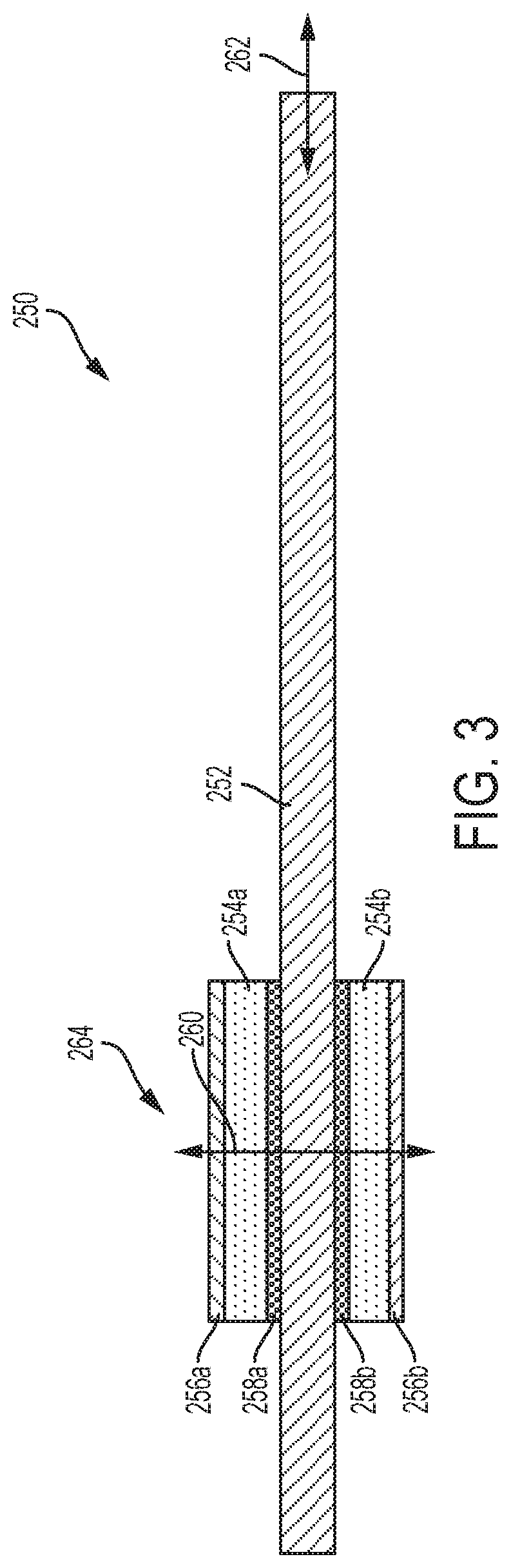
[0096] FIG. 3 illustrates an ultrasonic surgical instrument 250 that includes an ultrasonic waveguide 252 attached to an ultrasonic transducer 264 by a bonding material, where the ultrasonic surgical instrument 250 is configured to operate in a D31 mode, according to one aspect of the present disclosure. The ultrasonic transducer 264 includes first and second piezoelectric elements 254a, 254b attached to the ultrasonic waveguide 252 by a bonding material. The piezoelectric elements 254a, 254b include electrically conductive plates 256a, 256b to electrically couple one pole of a voltage source suitable to drive the piezoelectric elements 254a, 254b (e.g., usually a high voltage). The opposite pole of the voltage source is electrically coupled to the ultrasonic waveguide 252 by electrically conductive joints 258a, 258b. In one aspect, the electrically conductive plates 256a, 256b are coupled to a positive pole of the voltage source and the electrically conductive joints 258a, 258b are electrically coupled to ground potential through the metal ultrasonic waveguide 252. In one aspect, the ultrasonic waveguide 252 is made of titanium or titanium alloy (i.e., Ti6Al4V) and the piezoelectric elements 254a, 254b are made of a lead zirconate titanate intermetallic inorganic compound with the chemical formula Pb[ZrxTi.sub.1-x]O.sub.3 (0.ltoreq.x.ltoreq.1). Also called PZT, it is a ceramic perovskite material that shows a marked piezoelectric effect, meaning that the compound changes shape when an electric field is applied. It is used in a number of practical applications such as ultrasonic transducers and piezoelectric resonators PZT. The poling axis (P) of the piezoelectric elements 254a, 254b is indicated by the direction arrow 260. The motion axis of the ultrasonic waveguide 252 in response to excitation of the piezoelectric elements 254a, 245b is shown by a motion arrow 262 at the distal end of the ultrasonic waveguide 252 generally referred to as the ultrasonic blade portion of the ultrasonic waveguide 252. The motion axis 262 is orthogonal to the poling axis (P) 260.
[0097] In conventional D33 ultrasonic transducer architectures as shown in FIG. 1, the bolted piezoelectric elements 32 utilize electrodes 34, 36 to create electrical contact to both sizes of each piezoelectric element 34. The D31 architecture 250 according to one aspect of the present disclosure, however, employs a different technique to create electrical contact to both sides of each piezoelectric element 254a, 254b. Various techniques for providing electrical contact to the piezoelectric elements 254a, 254b include bonding electrical conductive elements (e.g., wires) to the free surface of each piezoelectric element 254a, 254b for the high potential connection and bonding each piezoelectric element 254a, 254b the to the ultrasonic waveguide 252 for the ground connection using solder, conductive epoxy, or other techniques described herein. Compression can be used to maintain electrical contact to the acoustic train without making a permanent connection. This can cause an increase in device thickness and should be controlled to avoid damaging the piezoelectric elements 254a, 254b. Low compression can damage the piezoelectric element 254a, 254b by a spark gap and high compression can damage the piezoelectric elements 254a, 254b by local mechanical wear. In other techniques, metallic spring contacts may be employed to create electrical contact with the piezoelectric elements 254a, 254b. Other techniques may include foil-over-foam gaskets, conductive foam, solder. Electrical connection to both sides of the piezoelectric elements 254a, 254b the D31 acoustic train configuration. The electrical ground connection can be made to the metal ultrasonic waveguide 252, which is electrically conductive, if there is electrical contact between the piezoelectric elements 254a, 254b and the ultrasonic waveguide 252.
[0098] In various aspects, as described below, an ultrasonic medical device may comprise a transducer configured to produce longitudinal vibrations, and a surgical instrument having a transducer mounting portion operably coupled to the transducer, an end effector, and wave guide therebetween. In certain aspects, as also described below, the transducer can produce vibrations which can be transmitted to the end effector, wherein the vibrations can drive the transducer mounting portion, the wave guide, the end effector, and/or the other various components of the ultrasonic medical device at, or near, a resonant frequency. In resonance, a longitudinal strain pattern, or longitudinal stress pattern, can develop within the transducer, the wave guide, and/or the end effector, for example. In various aspects, such a longitudinal strain pattern, or longitudinal stress pattern, can cause the longitudinal strain, or longitudinal stress, to vary along the length of the transducer mounting portion, wave guide, and/or end effector, in a sinusoidal, or at least substantially sinusoidal, manner. In at least one aspect, for example, the longitudinal strain pattern can have maximum peaks and zero points, wherein the strain values can vary in a non-linear manner between such peaks and zero points.
[0099] In conventional D33 ultrasonic transducer architectures as shown in FIG. 1, a bolt provides compression that acoustically couples the piezoelectric elements rings to the ultrasonic waveguide. The D31 architecture 250 according to one aspect of the present disclosure employs a variety of different techniques to acoustically couple the piezoelectric elements 254a, 254b to the ultrasonic waveguide 252. These techniques are disclosed hereinbelow.
[0100] FIG. 4A illustrates an aspect of an ultrasonic medical device 300 that incorporates one or more piezoelectric transducers 312a,b configured to operate in a D31 mode. The ultrasonic medical device 300 may include a surgical tool 301 having a waveguide 310 and a transducer mounting portion 320 (e.g., a transducer base plate). In some aspects, the surgical tool 301 may be fabricated from sheet stock and have essentially flat faces 325 and side edges 327 orthogonal to the flat faces 325. The waveguide 310 may include an end effector at a distal end and a longitudinal portion connecting the end effector with the transducer mounting portion 320 (located at a proximal end of the surgical tool 301). One or more piezoelectric transducers 312a,b may be affixed to the transducer mounting portion 320 of the surgical tool 301. In certain aspects, the waveguide 310 may also include one or more stabilizing silicone rings or compliant supports 306 positioned at, or at least near, a plurality of vibration nodes, which may dampen undesirable vibration and isolate the ultrasonic energy from a sheath at least partially surrounding the surgical tool 301. In order for the piezoelectric transducers 312a,b to operate in a D31 mode, a first electrode may be electrically coupled to an exposed face of a transducer (for example 312a) that is opposite to the face of the transducer in mechanical communication with a face 325 of the surgical tool 301. In some aspects, a conductive electrode (for example, a silver electrode) may be painted or screen printed on an exposed face of the piezoelectric transducers 312a,b and conducting wires may then be soldered onto the conductive electrodes. Alternatively, the wires may be affixed to the exposed faces of the piezoelectric transducers 312a,b by means of a conductive epoxy. The surgical tool may be electrically coupled to a second electrode, thereby permitting an electric field to be imposed on the piezoelectric transducer orthogonal to a longitudinal axis of the surgical tool 301.
[0101] FIG. 4B is a close-up view of the transducer mounting portion 320 of the ultrasonic medical device of FIG. 4A, illustrating the mechanical contacts that may be made between a face of each of the piezoelectric transducers 312a,b and a face 325 of the surgical tool 301. In the aspect illustrated in FIG. 4B, a single pair of piezoelectric transducers 312a,b contact the surgical tool 301 based on a face of each transducer 312a,b contacting an opposing face of the surgical tool. It may be observed that each of the pair of piezoelectric transducers 312a,b is positioned opposite the other. As disclosed above with respect to FIG. 1, the piezoelectric transducers 312a,b may be activated by a power source at a predetermined frequency to induce a standing mechanical wave along the body of the surgical tool 301. The standing wave may be proportional to the predetermined frequency component of the electrical signal. The standing wave induced along the body of the surgical tool 301 may be characterized by one or more nodes and anti-nodes. The standing wave nodes may be effectively centered at one or more node locations on the surgical tool 301, and the standing wave anti-nodes may be effectively centered at one or more anti-node locations on the surgical tool 301. Each piezoelectric transducer 312a,b may be symmetrically disposed about a node location in the transducer mounting portion 320 of the surgical tool 301. Such a disposition may result in each transducer 312a, b contacting a portion of the surgical tool 301 at a location having minimal mechanical displacement during the activation of the transducers 312a,b.
[0102] FIG. 5 illustrates a mechanism for attaching a piezoelectric transducer to the transducer mounting portion 320 of a surgical tool. A node location 510 of the surgical tool at the transducer mounting portion 320 may be identified based on the wavelength of the standing wave induced in the surgical tool. An electrically conductive adhesive 520 may be applied to the face 325 of the transducer mounting portion 320 centered around the node location 510 of the surgical tool. Additionally, a high strength adhesive 530 may be applied to the face 325 of the transducer mounting portion 320 near the electrically conductive adhesive 520 and somewhat distant from the node location 510. In some aspects, the electrically conductive adhesive 520 may include an electrically conductive epoxy adhesive. In some aspects, the high strength adhesive 530 may include a high strength epoxy adhesive. As disclosed above, the piezoelectric transducers may operate in a D31 mode if the activating electric field is oriented orthogonal to the axis of the surgical tool. Thus, a first electrode may contact the piezoelectric transducer on one face opposing the face of the transducer in contact with the surgical tool. The surgical tool may form the second electrode. The electrically conductive adhesive 520 may thus provide the piezoelectric transducer with an electrical contact with the surgical tool, while the high strength adhesive 530 may form a mechanically stable contact between the piezoelectric transducer and the surgical tool.
[0103] FIGS. 6-9 depict alternative aspects of an ultrasonic medical device including multiple pairs of piezoelectric transducers. FIG. 6 illustrates the transducer mounting portion 320 of a surgical tool having a first pair of piezoelectric transducers 312a,b contacting the surgical tool and each of a second pair of piezoelectric transducers 612a,b may contact an exposed face of one of the first pair of transducer 312a,b. The second pair of piezoelectric transducers 612a,b may have the same or smaller dimensions as the first pair 312a,b.
[0104] FIG. 7 depicts a total of four piezoelectric transducers 712a-d disposed as a pair of transducers 712a,b contacting a first face of the transducer mounting portion 320 of the surgical tool and a second pair of transducer 712c,d disposed opposite to the first pair of transducers 712a,b and contacting an opposing face of the surgical tool. In some aspects, piezoelectric transducers 712a and 712c may be disposed on one side of a node location of the transducer mounting portion 320, while piezoelectric transducers 712b and 712d may be disposed adjacent to piezoelectric transducers 712a and 712c, respectively, and on a second side of the node location.
[0105] In another aspect, illustrated in FIG. 8, a total of four piezoelectric transducers 812a-d disposed as a pair of transducers 812a,b contacting a first face of the transducer mounting portion 320 of the surgical tool and a second pair of transducer 812c,d disposed opposite to the first pair of transducers 812a,b and contacting an opposing face of the surgical tool. In some aspects, piezoelectric transducers 812a and 812c may be disposed at some distance from a node location of the transducer mounting portion 320, while piezoelectric transducers 812b and 812d may be disposed symmetrically about the node location with respect to piezoelectric transducers 812a and 812c and at the same distance from the node location. Alternatively, piezoelectric transducers 812a and 812c may be centered about a first node location of the transducer mounting portion 320, while piezoelectric transducers 812b and 812d may be centered about a second node location.
[0106] FIG. 9 illustrates an aspect in which a first transducer 912a comprises a first planar array of first transducer plates and the second transducer 912b comprises a second planar array of second transducer plates. As illustrated in FIG. 9, the first transducer 912a comprises a first planar array of first transducer plates indicated by numbers 1, 2, 3, and 4. The second transducer 912b comprises a second planar array of second transducer plates (not visible in the perspective view of FIG. 9) indicated by numbers in parentheses (5), (6), (7), and (8). It may be understood that second transducer plate (5) is disposed on an opposing side of the transducer mounting portion 320 with respect to first transducer plate 1, second transducer plate (6) is disposed on an opposing side of the transducer mounting portion 320 with respect to first transducer plate 2, second transducer plate (7) is disposed on an opposing side of the transducer mounting portion 320 with respect to first transducer plate 3, and second transducer plate (8) is disposed on an opposing side of the transducer mounting portion 320 with respect to first transducer plate 4. Transducer plates 1, (5), 3, and (7) may be disposed about one side of a node location and transducer plates 2, (6), 4, and (8) may be disposed about an opposing side of the node location.
[0107] It may be understood that the transducers or transducer plates depicted in the aspects in FIGS. 1, 3-4, 6-9 may all be made of the same material. Alternatively, the transducers or transducer plates depicted in the aspects in FIGS. 1, 3-4, 6-9 may be made of different materials. For example the transducers or transducer plates may be fabricated from piezoelectric materials that differ in their respective strain constants, dielectric dissipation or dampening properties, dielectric constants, voltage sensitivities, or Currie temperatures. Similarly, the transducers or transducer plates may all have the same shape and size. Alternatively, transducers or transducer plates may differ in shape, size, or both shape and size depending on their respective placements on the surgical tool or on each other.
[0108] Each transducer or transducer plate illustrated in FIGS. 1, 3-4, 6-9 may be individually activated. In some aspects, each transducer or transducer plate may be activated by a separate ultrasonic signal generator in which the individual ultrasonic signal generators have a common ground in electrical communication with the surgical tool. In such an aspect, each transducer or transducer plate may be activated by a separate electric signal. In some examples, the electrical characteristics of the separate electrical signals may be the same, for example having the same amplitude, frequency, and phase. In alternative examples, the electrical characteristics of the separate electrical signals may differ in one or more of amplitude, frequency, and phase. In alternative aspects, each transducer or transducer plate may be activated by the same ultrasonic signal generator, but may be separately activatable by one or more transducer activation switches. Such switches may direct a first polarity of an ultrasonic signal to one set of transducers or transducer plates and a second polarity of the ultrasonic signal to a second set of transducers or transducer plates. It may be understood that such switches may also be used to disconnect one or more transducers or transducer plates from the ultrasonic signal generator while allowing other transducers or transducer plates to receive an ultrasonic signal from the ultrasonic signal generator.
[0109] In at least one such aspect, the surgical instrument can comprise a handle which can comprise one or more switches which can be configured to selectively actuate the transducers or transducer plates. For example, a switch can be moved from an off position to a first position in order to actuate a first transducer or set of transducer plates, to a second position to actuate the second transducer or set of transducer plates. It may be recognized that in an aspect such as depicted in FIG. 9, such a switch may have multiple positions, each position configured to actuate a specified group of transducer plates. In certain other aspects, a handle can comprise a first switch configured to selectively actuate a first transducer or set of transducer plates, and, in addition, a second switch configured to selectively actuate the second transducer or set of transducer plates. In such aspects, the surgeon can select the power to be supplied to the surgical tool and/or end effector.
[0110] It may be recognized that switched activation of the transducers or transducer plates may result in vibrational patterns of the surgical tool that are more complex than a single longitudinal standing mechanical wave. Such complex mechanical waves may be used to impart complex movement to the end effector of the surgical tool. For example, with respect to the aspect illustrated in FIG. 9, a predominantly transverse flapping motion may be induced in the end effector if transducer plates 1, 2, (5), and (6) are activated with a first polarity ultrasonic signal while transducer plates 3, 4, (7), and (8) are activated with a second and opposing polarity ultrasonic signal. A predominantly transverse hooking motion may be induced in the end effector if transducer plates 1, (5), 3, and (7) are activated with a first polarity ultrasonic signal while transducer plates 2, (6), 4, and (8) are activated with a second and opposing polarity ultrasonic signal. A predominantly torsional motion may be induced in the end effector if transducer plates 1, (7), 2, and (8) are activated with a first polarity ultrasonic signal while transducer plates 3, (5), 4, and (6) are activated with a second and opposing polarity ultrasonic signal. A combination of torsional and transverse motions may be induced in the end effector if transducer plates 1, (7), 4, and (6) are activated with a first polarity ultrasonic signal while transducer plates (5), 3, 2, and (8) are activated with a second and opposing polarity ultrasonic signal. Additional motions may be achieved through the activation of other groups of transducer plates.
[0111] FIGS. 10 and 11 illustrate additional mechanisms by which the transducers may be affixed onto the surgical tool. The piezoelectric transducers may be mounted on the transducer mounting portion 320 of a surgical tool. The face 325 of the surgical tool may be machined to form a pocket in which the piezoelectric transducers may be mounted. As illustrated in FIG. 10, the piezoelectric transducers 1012a,b may have a width approximately equal to the width of the surgical tool, so the pocket may be fabricated across the width of the surgical tool and may extend to the edges 1027 of the surgical tool. As illustrated in FIG. 11, the piezoelectric transducers 1112a,b may have a width less than the width of the surgical tool, so the pocket may be fabricated within the width of the surgical tool but may not extent to the edges 1127 of the surgical tool. As illustrated in FIGS. 10 and 11, the thickness of the surgical tool within the pocket may be less than the overall thickness of the surgical tool. The piezoelectric transducers (1012a,b in FIGS. 10 and 1112a,b in FIG. 11) may be fixed within the respective pockets through the use of one or more adhesives, such as electrically conductive adhesives and/or high strength adhesives. Alternatively, the piezoelectric transducers (1012a,b in FIGS. 10 and 1112a,b in FIG. 11) may be fixed within the respective pockets by means of an interference fit. The interference fits may be accomplished by heating and cooling the surgical tool, thereby causing thermal expansion and contraction of the pocket of the surgical tool. The interference fits may also be accomplished by activating and deactivating the piezoelectric transducers, thereby causing piezoelectric expansion and contraction of the piezoelectric transducers.
[0112] FIGS. 12 and 13 illustrate further mechanisms by which the transducers may be affixed onto the surgical tool by the use of one or more clips. FIG. 12 illustrates the use of a single clip 1210, such as a C-clip that may compress each of the piezoelectric transducers 312a,b against their respective faces of the transducer mounting portion 320 of the surgical tool. FIG. 13 depicts clips 1310a,b that may be used to apply a pre-loading compression across a longitudinal direction of the piezoelectric transducers 312a,b. The piezoelectric transducers 312a,b illustrated in FIG. 13 may be affixed to the surgical tool through one or more adhesives as disclosed above (for example in FIG. 5).
[0113] The ultrasonic medical device depicted in FIG. 3 may also incorporate features for mounting in an ultrasound system. FIG. 14 illustrates an aspect of an ultrasonic medical device adapted for mounting in a housing. As depicted in FIG. 14, the ultrasonic medical device may include a surgical tool having a transducer mounting portion 320 comprising faces (such as face 325) and edges such as edge 327). Piezoelectric transducers 312a,b may be mounted on the transducer mounting portion 320 and disposed symmetrically about a node location in the surgical tool. The surgical tool may be fabricated to incorporate flanges 1410a,b located at the node location on opposing edges 327a,b of the surgical tool. As depicted in FIG. 14, the first flange (for example 1410a) may extend from a first side edge 327a of the surgical tool and the second flange (for example 1410b) may extend from an opposing side edge 327b of the surgical tool, so that each of the first flange 1410a and the second flange 1410b may be symmetrically disposed about the node location in the surgical tool.
[0114] In various aspects, further to the above, an ultrasonic medical device may comprise a surgical tool comprising a transducer mounting portion, a waveguide, and an end effector, along with one or more piezoelectric transducers affixed thereon. The ultrasonic medical device may further comprise a housing at least partially surrounding the transducer mounting portion of the surgical tool and a sheath at least partially surrounding the waveguide and/or end effector. In at least one aspect, an ultrasonic medical device can comprise one or more piezoelectric transducers, a housing encompassing transducer mounting portion, waveguide, a sheath encompassing the waveguide, and an end effector. In certain aspects, the ultrasonic medical device can further comprise one or more stabilizing supports which can be configured to support the waveguide and/or end effector within the sheath. In at least one such aspect, the sheath can comprise a handle portion and/or can be configured to be grasped, or gripped, by a surgeon such that the surgeon can accurately manipulate the ultrasonic medical device and, in particular, accurately manipulate a distal end of the end effector. In at least one aspect, at least a portion of the outer surface of the sheath can comprise a roughened and/or textured surface. In certain aspects, the outer surface of the sheath can comprise a round, or at least substantially round, cross-section having a diameter of approximately 5 millimeters, approximately 10 millimeters, approximately 15 millimeters, and/or a diameter between approximately 4 millimeters and approximately 16 millimeters.
[0115] The ultrasonic medical device of FIG. 14 may be mounted in a housing as depicted in FIG. 15. The transducer mounting portion 320 may be mounted within a housing 1520 that includes retainers 1525a,b, in which each retainer 1525a,b is configured to receive one of the flanges 1410a,b. Such an arrangement may allow the surgical tool to move according to the standing wave induced therein, while being held securely in the housing 1520 at a node point that generally does not move while the piezoelectric transducers are activated. FIG. 16 illustrates an additional aspect for securing an ultrasonic medical device within a housing. FIG. 16 depicts the transducer mounting portion 320 of a surgical tool having a pair of piezoelectric transducers 312a,b mounted thereon. The housing may include a shroud 1620 that may surround the surgical tool. The shroud 1620 may include one or more contacts 1625a,b configured to apply a compressive force to the piezoelectric transducers 312a,b. The contacts 1625a,b may be designed to apply the compressive force to the piezoelectric transducers 312a,b approximately at a node location of the surgical tool when the piezoelectric transducers 312a,b are activated by an ultrasound generator. The contacts 1625a,b may be electrically conductive to permit power from the ultrasound generator to activate the piezoelectric transducers 312a,b. Alternatively, the contacts 1625a,b may include electrically conducting surfaces 1627a,b that directly contact the exposed surfaces of the piezoelectric transducers 312a,b. The electrically conducting surfaces 1627a,b that may be placed in electrical communication with the ultrasound generator to conduct energy from the ultrasound generator to the piezoelectric transducers 312a,b. Aspects of the ultrasonic medical device, as disclosed above, incorporate a surgical tool generally described as being manufactured from flat stock. However, additional aspects may include a surgical tool that may be manufactured from round stock or square stock (such as a long bar). FIGS. 17 and 18 depict aspects of an ultrasonic medical device manufactured from either round or square stock. Such an ultrasonic medical device may have a waveguide 1710 having a cylindrical or truncated conical cross section and a transducer mounting portion 1720 having a square or rectangular cross section. Alternatively, the waveguide 1710 may have the form of a double wedge with appropriate tips to achieve desired tissue effect. Double-wedge horns are well known in ultrasonic welding.
[0116] The transducer mounting portion 1720 of such an ultrasonic device may be described as having the form of a square or rectangular prism. While a surgical tool manufactured from flat stock may have a single pair of surfaces (see 325 of FIG. 3) on which the piezoelectric transducers may be mounted, a surgical tool having a transducer mounting portion 1720 having the form of a square or rectangular prism may have four surfaces on which the piezoelectric transducers 1712a-c may be mounted (note that a fourth piezoelectric transducer, in addition to the three piezoelectric transducers 1712a-c illustrated in FIG. 17, may be affixed to a fourth side of the transducer mounting portion 1720 that is not shown in the view). The multiple piezoelectric transducers may be affixed to the surfaces of the transducer mounting portion 1720 using adhesives as disclosed above with respect to FIG. 5. Alternatively, a clip or band 1810 may be used to secure the multiple piezoelectric transducers. It may be understood that the clip or band 1810 may be designed to incorporate electrodes to supply an electrical signal to activate the multiple piezoelectric transducers.
[0117] FIGS. 17 and 18 depict a surgical tool with a transducer mounting portion 1720 having the form of a square or rectangular prism on which each of the piezoelectric transducers 1712a-c (including the transducer not depicted in the figures) may be mounted. It may be recognized that a piezoelectric transducer may be mounted on each of the four sides of the transducer mounting portion 1720 or only on a pair of opposing sides. Further, each of the piezoelectric transducers 1712a-c may comprise one or more transducer plates (similar in structure as depicted in FIG. 9). In some examples, the width of piezoelectric transducers 1712a-c may be half that of the piezoelectric transducers 312a,b (see FIG. 3) that may be used on surgical tools fabricated from flat stock to preserve the total volume. In some fabricated examples, a piezoelectric transducer, such as 1712a, was able to deliver 35 watts.
[0118] As disclosed above with respect to FIGS. 7-9, each of the piezoelectric transducers 1712a-c (including the hidden fourth transducer) may be activated by the same or different power supplied. If all four transducers are driven in parallel, the motion of the end effector of the surgical tool may be longitudinal (similar to the motion of a flat ultrasonic medical device comprising a surgical tool fabricated from sheet stock, as depicted in FIG. 3). However, if two transducers, located on opposing faces of the transducer mounting portion 1720 are driven out of phase, then a transverse motion may be produced in the end effector. If the two transducers on the other faces are driven out phase, then a transverse motion of the end effector may be produced in the opposite direction. Further, if each of a first pair of opposing transducers is driven at 180 degrees apart, and each of a second pair of opposing transducers is driven at 180 degrees apart and further are driven 90 degrees apart from the first pair, then an orbital motions may be produced at the end effector. It may be recognized that the geometry of the waveguide 1710 and driving frequency of the transducers may be designed to achieve a longitudinal, transverse, and orbital motion in one device.
[0119] Aspects depicted in FIGS. 17 and 18 may benefit from low-cost fabrication methods to produce a square/rectangular transducer with a relatively small cross section. As disclosed above, the use of independent activation signals to the transducers having appropriate driving characteristics in frequency and phase, may result in longitudinal, transverse (in two directions) and orbital motions. Such an orbital motion with a hollow blade may provide improved fragmentation and skeltonization of tissue. Additionally, such multiple controllable motions may form the basis for dynamic steering of an end effector, which may include a light source or sensor.
[0120] FIGS. 19 and 20 depict a cross section of an ultrasonic medical device manufactured from bar stock and round stock, respectively. FIG. 19 illustrates a medical device having a cylindrical waveguide 1910 machined from a bar stock, for example on a lathe. The un-machined portion, having a square cross-section, is retained at the transducer mounting portion 1920 of the medical device. A piezoelectric transducer (1912a-d) may be mounted on each surface of the transducer mounting portion 1920 of the device. FIG. 20 illustrates a medical device, comprising a transducer mounting portion 2020 having a square cross section, machined from round stock, for example by a milling machine. The un-machined portion, having a circular cross-section, is retained for the waveguide 2010. A piezoelectric transducer (2012a-d) may be mounted on each surface of the transducer mounting portion 2020 of the device.
[0121] FIG. 21 depicts another aspect of an ultrasonic medical device having a transducer mounting portion 2120 fabricated in the form of a triangular prism. Such a medical device may also include a waveguide 2110 having a round, flat, square, or other cross section as disclosed above. In one aspect, a piezoelectric transducer 2112 may be affixed to each of the faces (such as face 2125, as illustrated in FIG. 21). As disclosed above with respect to aspects having more than two transducers, each transducer may be activated from a common power supply or from individual power supplies. The transducers may also be activated in phase or out of phase. In one example, if all three transducers are driven in parallel, the motion of the end effector may be primarily longitudinal. In another example, in an aspect having a transducer mounting portion 2120 fabricated in the form of a triangular prism, the transducers may be activated 120 degrees apart from each other. Such an activation may result in a rotational or torsional motion at the end effector. If two of the transducers are driven with a greater amplitude than the third (including not driving the third at all), then a mainly lateral motion may be induced in the end effector.
[0122] Additionally, each of the transducers may be operated at a different frequency, which may result in more complex motions of the end effector. In another example, the current delivered to each transducer may be modulated so that one or two transducers may be activated with the other(s) off (inactivated for a period of time, and then one or two other transducers may be activated (with the first one or two transducers remaining in an off or inactivated state) after a brief rest period. The rest period may be long enough for transients to die down and drive at resonance for some time. For example, the rest period may be between about 0.1 and 1 msec. The use of such a rest period between successive activations of the transducers may be useful for "soft" start-ups and shut downs. As disclosed above with respect to FIG. 17, it may be recognized that the geometry of the waveguide 2110 and driving frequency of the transducers may be designed to achieve a longitudinal, transverse, and orbital motion in one device. It may be recognized that one-phase to three-phase converters are well known in industrial electrical systems to power motors, for example. It may also be possible to have a small converter on a circuit board that is contained in the transducer body. The 120 phase difference between the transducers may be achieved with lead- and lag-circuits from passive components.
[0123] The ultrasonic medical device depicted in FIG. 21 may be fabricated from a surgical tool having a triangular prismatic transducer mounting portion 2120. A piezoelectric transducer, such as transducer 2112, may be affixed to each of the faces 2125 of the surgical tool. In an alternative aspect, the ultrasonic medical device may lack a triangular prismatic transducer mounting portion 2120, but rather incorporate three piezoelectric transducers attached directly to each other along their neighboring length-wise edges. The waveguide 2110 may terminate at a proximal end with a triangular frame or plate to which the three piezoelectric transducers may be affixed at their respective distal edges.
[0124] Additionally, the ultrasonic medical device may include a lumen 2135 disposed within the device and fabricated along a central longitudinal axis thereof. The lumen 2135 may be used to transport a fluid, such as a cooling fluid, through the device. If the lumen 2135 extends throughout the entire length of the device, having a distal portal at a distal end of the end effector, the cooling fluid may be used to cool tissue contacting the end effector. Alternatively, the lumen 2135 may be in fluid communication with a proximal vacuum source that may be used to remove fluids from the tissue at the distal end of the end effector.
[0125] FIGS. 22-25 depict a variety of aspects of an ultrasonic medical device having a triangular prismatic transducer mounting portion. FIG. 22, for example, is a cross-sectional view of the ultrasonic medical device illustrated in FIG. 21. It may be observed that the transducer mounting portion 2120 has a piezoelectric transducer 2112a-c affixed to each of the faces of the transducer mounting portion 2120, and a central, cylindrical lumen 2135 disposed therein. FIG. 23, for example, is a cross-sectional view of the ultrasonic medical device having a transducer mounting portion 2320 that lacks a central lumen. FIG. 24, for example, is a cross-sectional view of the ultrasonic medical device having a hollow triangular prismatic transducer mounting portion 2420 that has a triangular lumen 2435. FIG. 25, for example, is a cross-sectional view of the ultrasonic medical device of FIG. 24, having a hollow triangular prismatic transducer mounting portion 2420 that has a triangular lumen 2435. FIG. 25 also illustrates that piezoelectric transducers 2512a-c may be mounted on the inner faces of the triangular lumen.
[0126] Generalizing from FIGS. 3-25, a surgical tool may include a transducer mounting portion fabricated in the form of a polygonal prism (the transducer mounting portion of the surgical tools disclosed in FIGS. 3-16 may be considered to have the form of a rectangular prism in which one set of opposing sides is much longer than the second set of opposing sides). It may be recognized that additional aspects of a surgical tool may include a transducer mounting portion having the form of a cylindrical or partially cylindrical prism.
[0127] FIGS. 26-31 are directed to aspects of an ultrasonic medical device comprising a surgical tool having a cylindrical, or partially cylindrical, transducer mounting portion. FIG. 26 illustrates an ultrasonic medical device 2600 comprising surgical tool having a cylindrical waveguide 2610 and a transducer mounting portion 2620 having the form of a horizontal cylindrical segment formed from a pair of sectional planes parallel to the long axis of the cylinder. The transducer mounting portion 2620 may further include a pair of parallel and opposing flat surfaces 2625 on which the piezoelectric transducers 312a,b may be mounted as disclosed above with respect to FIG. 5, for example.
[0128] FIG. 27 illustrates an ultrasonic medical device 2700 comprising a surgical tool having a cylindrical waveguide 2710 and a transducer mounting portion 2720 having the form of a cylindrical prism in which a pair of opposing flats 2725a,b may be fabricated to receive the piezoelectric transducers 312a,b. As disclosed with respect to FIGS. 10 and 11, the piezoelectric transducers 312a,b may be affixed to the flats 2725a,b by means of one or more types of adhesives. Alternatively, the piezoelectric transducers 312a,b may be affixed to the flats 2725a,b by means of an interference fit. The interference fits may be accomplished by heating and cooling the surgical tool, thereby causing thermal expansion and contraction of the transducer mounting portion 2720 surrounding the flats 2725a,b. The interference fits may also be accomplished by activating and deactivating the piezoelectric transducers, thereby causing piezoelectric expansion and contraction of the piezoelectric transducers.
[0129] FIG. 28 illustrates an ultrasonic medical device 2800 comprising a surgical tool having a cylindrical waveguide 2810 and a transducer mounting portion 2820 having the form of a cylindrical prism. The piezoelectric transducer 2812 may have the form of a ring or a tube. In one aspect, the surgical tool 2800 may be fabricated from a separate waveguide 2810 and a transducer mounting portion 2820. The transducer mounting portion 2820 may include a machined portion having a smaller diameter than the remaining transducer mounting portion 2820 to receive the piezoelectric transducer 2812 (see FIG. 29). An ultrasonic medical device comprising the surgical tool 2800 and the piezoelectric transducer 2812, may be assembled from the waveguide 2810, the transducer mounting portion 2820, and the piezoelectric transducer 2812. During fabrication, a flange portion of the waveguide 2810 may be secured against an edge of the piezoelectric transducer 2812, thereby applying longitudinal compression against the transducer. In one example, the waveguide 2810 may include a threaded portion that may be threaded into a mating portion of the transducer mounting portion 2820 to assemble the ultrasonic medical device.
[0130] FIG. 29 illustrates a cross-sectional view of the transducer mounting portion 2820 of the ultrasonic medical device depicted in FIG. 28, illustrating the piezoelectric transducer 2812 placed over smaller diameter machined portion 2950 of the transducer mounting portion 2820. It may be recognized that good conduction of the mechanical vibrations created by an energized cylindrical piezoelectric transducer 2812 into the waveguide may require tight mechanical coupling between the piezoelectric transducer 2812 and the waveguide 2810. Further, for the piezoelectric transducer 2812 to operate in a D31 mode, electrodes must form electrical contacts with the outer surface and the inner surface of the piezoelectric transducer 2812. In some aspects, an electrode connected to a hot conductor of an ultrasound power generator may contact an exposed surface of a transducer, while the surgical tool, contacting the opposing face of the transducer, may be in electrical contact with the neutral conductor of the ultrasound power supply. Because the piezoelectric transducer 2812 may be formed from a ceramic, it may be difficult to assure that the inner surface of the piezoelectric transducer 2812 forms a good electrical contact with the machined portion 2950 of the transducer mounting portion 2820. If a gap between the machined portion 2950 and the inner surface of the piezoelectric transducer 2812 is small (for example about 0.005 inches), the gap may be filled with a conductive epoxy 2930 and still deliver the needed power. Alternatively, a "green" (or un-fired) piezoelectric ceramic material may be assembled on the surgical tool and co-fired along with the surgical tool. In another alternative method of fabrication, the metallic portions of the ultrasonic medical device may be assembled with a piezoelectric ceramic that is between the green state and the fully fired state.
[0131] FIG. 30 illustrates yet another aspect of an ultrasonic medical device 3000 composed of a surgical tool having a cylindrical waveguide 3010 and a cylindrical prismatic transducer mounting portion 3020. The ultrasonic medical device 3000 may be distinguished from the ultrasonic medical device 2800 in that the transducer comprises a plurality of cylindrical piezoelectric plates 3012a,b. Such cylindrical piezoelectric plates 3012a,b may be considered as being formed from longitudinal sections of a single tubular piezoelectric transducer 2812 as illustrated in FIG. 28. There may be two, three, or more cylindrical piezoelectric plates 3012; two such cylindrical piezoelectric plates 3012a,b are depicted in FIG. 30.
[0132] FIG. 31 is a cross-sectional view 3120 of the transducer mounting portion 3020 of the ultrasonic medical device 3000 illustrated in FIG. 30. It may be recognized that the cylindrical piezoelectric plates 3012a,b depicted in FIG. 30 comprise a ceramic material that may be difficult to machine to permit a close fit, both to each other (along their respective length-wise edges) and to the machined portion 3150 of the transducer mounting portion 3120. As depicted in FIG. 31, the ultrasonic medical device (3000 of FIG. 30) may include cylindrical piezoelectric plates 3112a-c that do not contact each other along their respective length-wise edges, but may be fabricated so that their inner surfaces may conform more closely to the machined portion 3150 of the transducer mounting portion 3120. The cylindrical piezoelectric plates 3112a-c may then be affixed to the machined portion 3150 of the transducer mounting portion 3120 using a conductive epoxy 3230. As disclosed above with respect to other aspects of ultrasonic medical devices, for example the device depicted in FIG. 21, each of the individual cylindrical piezoelectric plates 3112a-c may be activated independently. For example, in the aspect depicted in FIG. 31, the three cylindrical piezoelectric plates 3112a-c may be activated by piezoelectric driving signals that are 120 degrees out of phase. Other examples of methods for activating three cylindrical piezoelectric plates 3112a-c may include those disclosed above with respect to FIG. 21. As noted above, other examples of an ultrasonic medical device 3000 may include 2, 3, 4, or more piezoelectric transducers that may be activated synchronously, asynchronously, or with a variety of ultrasound activation signals that may differ in frequency, phase, or amplitude.
[0133] Although the aspects disclosed above in FIGS. 3-31 are directed to a plurality of piezoelectric transducers positioned relative to the location of a single (for example proximal) vibrational node induced in a surgical tool, it may be recognized that transducers may similarly be positioned relative to more than one vibrational node. As disclosed above, the plurality of piezoelectric transducers may be activated by a single source of ultrasonic power or multiple sources of ultrasonic power, and may be operated synchronously or asynchronously. The electrical characteristics, such as frequency, amplitude, and phase, of the ultrasonic power may be the same or may differ among all of the plurality of piezoelectric transducers.
[0134] FIG. 32 illustrates aspects of a surgical tool 3200. In some aspects, the surgical tool 3200 may be used as part of an ultrasonic system 10 as depicted in FIG. 1. Alternatively, one or more piezoelectric transducers may be mounted on the surgical tool 3200 to form an ultrasonic medical device, for example 300 as depicted in FIG. 3. The surgical tool 3200 may comprise a proximal transducer mounting portion 3220, a distal end effector 3260 and a longitudinal portion or waveguide 3210 therebetween. The surgical tool 3200 may also comprise an attachment boss 3280 that may permit the surgical tool 3200 to be mounted in a housing or other ultrasonic system. Such a surgical tool 3200 may be manufactured from titanium stock or from aluminum stock although any material having appropriate mechanical and/or electrical characteristics may be used.
[0135] FIG. 33 illustrates a close-up view of the end effector 3260 and the distal end of the waveguide 3210. The waveguide 3210 may have a rectangular cross section as depicted in FIG. 33 although the cross section may of any polygon as may be appropriate for its use. Alternatively, the cross section may be elliptical or circular. The end effector 3260 may be fabricated as an integral part of the surgical tool, or may comprise a separate component affixed onto the waveguide 3210. The end effector 3260 may have a curved shape and may curve either in a vertical or horizontal direction with respect to the longitudinal axis of the surgical tool as may be appropriate for its use. Alternatively, the end effector 3260 may comprise a straight section that is bent at some angle, either vertically or horizontally, from the longitudinal axis of the surgical tool. In other examples, the end effector 3260 may comprise a more complex geometry including straight sections and curved sections, or multiple curved sections that differ in their respective radii of curvature. The end effector 3260 may extend directly from the waveguide 3210 or the waveguide 3210 may include shoulders from which the end effector 3260 extends.
[0136] In various aspects, the length and mass of a surgical tool comprising a transducer mounting portion, a wave guide, and/or an end effector can dictate the resonant frequency of the surgical tool. In various circumstances, the length of the surgical tool can be selected such that the resonant frequency of the surgical tool is within a range of frequencies that a voltage or current source can supply to a piezoelectric transducer coupled thereto. In certain aspects, a given transducer, wave guide, and/or end effector may be required to be used together and, in the event that a different length wave guide or different end effector is needed, a different surgical tool altogether may be required.
[0137] FIG. 34 illustrates an example of a surgical tool 3200 mounted within an ultrasound medical system comprising a housing 3475 or a handle. The surgical tool 3200 may be secured to or within the housing 3475 according to any means consistent with its function and use. For example, the surgical tool 3200 may be secured to the housing 3475 by means of a clamp, clip, or collet 3470. For example, such an ultrasound medical system may use the surgical tool 3200 alone to contact a tissue for therapeutic means.
[0138] FIG. 35 illustrates a more complex ultrasound medical system, such as an ultrasound shear 3500, in which a surgical tool may be incorporated. The ultrasound shear 3500 may include a surgical tool (the end effector 3260 of the surgical tool being illustrated) which may operate against an anvil 3553. The anvil 3553 may be moved by a movable handle 3550. The movable handle 3550 may be manipulated so that a tissue 3580 contacted by the anvil 3553 may be brought into contact with the end effector 3260. The surgical tool may be affixed to the ultrasound shear 3500 by means of a clamp, clip, or collet 3570.
[0139] It may be recognized that the utility of an ultrasound surgical tool is based on the standing mechanical vibrational waves that may be induced therein by an associated piezoelectric transducer. Owing to various manufacturing differences, however, each surgical tool may have a slightly different resonant frequency and, as a result, each surgical tool may be tested in order to find its resonant frequency. If it is determined that the natural frequency of the surgical tool needs to be adjusted, the transducer mounting portion of the surgical tool and/or the end effector may be ground in order to adjust their length and, as a result, adjust the resonant frequency of the surgical tool. Although such manufacturing methods may be useful for their intended purposes, the process may be time consuming and/or may not provide adequate adjustability of the surgical tool. For example, in the event that too much length is ground off of a surgical tool transducer mounting portion, for example, the surgical tool typically may be thrown out and the adjustment process must be repeated with a new surgical tool. More efficient processes for fabrication of surgical tools is therefore useful.
[0140] FIG. 36 illustrates a portion of a method of fabrication of one or more surgical tools, such as surgical tool 3600. Each surgical tool 3600 may comprise a transducer mounting portion 3620, an end effector 3660, and an elongated portion or waveguide 3610 therebetween. The surgical tool 3600 may also incorporate additional features such as a gain feature 3655 to modify the amplitude of the mechanical wave induced in the surgical tool 3600 by the activated piezoelectric transducers driving it. Additional features may include one or more blade attachment features 3626a,b that may be used for attaching the surgical tool to a housing or ultrasound medical system. In some examples, the attachment features 3626a,b may be fabricated at one or more node locations of the surgical tool 3600 where mechanical displacement during piezoelectric activation may be minimized.
[0141] The surgical tool 3600 may be fabricated from sheet stock 3607 comprising titanium or aluminum. Titanium or other surgical tool 3600 material may be rolled, pressed, molded, or cast into sheets 3607 in a manner that creates the best material microstructure and orientation (grain) to produce efficient surgical tools 3600. The surgical tools 3600 may be "blanked" by way of laser machining, laser machining with tilt degree of freedom, wire EDM, conventional milling, stamping, fine blanking, or other two dimensional cutting method from the sheet 3607. In some aspects, the surgical tools 3600 may be bulk finished to round edges by way of tumbling, sand blasting, bead blasting, electropolishing, forging, coining, or other finishing methods. In alternative aspects, only those areas or features on the surgical tool 3600 that require further shape refinement may be machined to their final dimensions. Such portions of the surgical tool 3600 may include, for example, the exposed portion of the end effector 3660, the proximal transducer mounting portion 3620, surfaces or other features. Other surfaces may be untouched, or at most rough-shaped. Examples of such unfinished portions may include a portion of the surgical tool 3600 that may be contained inside a housing of a ultrasound medical system incorporating the surgical tool 3600.
[0142] Further fabrication steps may include removing material from the thickness of the part by machining, skiving, forming, coining, forging, or other methods known in the art. This additional machining may be performed on only one side or the surgical tool 3600 or on opposing sides of the surgical tool 3600. Such additional machining to adjust the thickness of the surgical tool 3600 may be used to form a gain feature 3655 to modify the amplitude of the mechanical wave induced in the surgical tool 3600 by the activated piezoelectric transducers driving with it. In some aspects, the gain features 3655 may be fabricated starting at a location proximal to an antinode and ending at a location distal to the antinode. The fabricated gain features 3655 may incorporate regions of high mechanical gain of the waveguide 3610 thereby minimizing the part-to-part variation in gain. The resulting thickness of the part by removal or reduction may yield a section of the surgical tool 3600 that is at or near the lower end of the standard sheet thickness tolerance.
[0143] Typical thickness tolerance on sheet stock materials such as sheet titanium or aluminum may be about +/-0.0080 inches or +/-0.203 mm. This tolerance is roughly four to eight times that which may be found in ultrasonic surgical tools machined via precise turning operations (e.g., lathe, Swiss screw machine, etc.). The displacement gain through a waveguide 3610 is related to changes in cross sectional area of the member. Therefore, large variation in the lateral aspects of a transmission member (such as thickness variation) may result in large part-to-part variation in displacement gain. Therefore, precision tuning of the displacement gain between surgical tools may be accomplished through such additional machining. It may be recognized that changes in area at or near antinodes of vibration have little to no effect on displacement gain, while changes in area at or near nodes of vibration have maximal effect on displacement gain.
[0144] As disclosed above, precision tuning of the displacement gain between surgical tools may be accomplished through appropriate precision machining of a surgical tool. An additional manner to tune the vibrational characteristics of a surgical tool may be to fabricate the surgical tool in a specified direction with respect to the grain orientation of the sheet stock from which it is manufactured, specifically orienting a longitudinal axis of the tool with respect to the grain orientation of the sheet stock. FIG. 37 illustrates surgical tools 3700a-c that may be machined according to the grain pattern of the sheet stock from which they are manufactured. Thus, surgical tool 3700a is fabricated having a transverse grain pattern 3707a, in which the longitudinal axis of the surgical tool 3700a is oriented orthogonal to the grain direction. Surgical tool 3700b is fabricated to have a longitudinal grain pattern 3707b, in which the longitudinal axis of the surgical tool 3700b is oriented parallel to the grain direction. Surgical tool 3700c is fabricated to have the longitudinal axis of the surgical tool 3700c oriented in another direction with respect to the grain orientation. In some applications, the longitudinal axis of the surgical tool is oriented at an angle with respect to the grain direction to minimize stress in at least a portion of the surgical tool upon activation. In other applications, the longitudinal axis of the surgical tool is oriented at an angle with respect to the grain direction to maximize a longitudinal deflection of the surgical tool upon activation.
[0145] The properties of such surgical tools, based on samples fabricated from titanium alloy Ti 6Al4V ELI have been determined as follows. A surgical tool 3700a, having a transverse grain 3707a may have a stiffness, E=18,520,000 PSI 55.5 and a quarter-wave length (at 55.5 kHz)=0.952 inches. A surgical tool 3700b, having a longitudinal grain 3707b may have a stiffness, E=16,310,000 PSI, and a quarter-wave length (at 55.5 kHz)=0.894 inches. These values may be compared to un-oriented rod stock which may have a stiffness, E=15,680,000 PSI a quarter-wave length (at 55.5 kHz)=0.876 inches. The choice of grain orientation for a surgical tool may help maximize the end effector length by minimizing the error in perpendicularity from the centerline of the end effector to the grain direction. For example, a transverse grain orientation 3707a may result in a minimal error (theoretically zero) and maximum length for a surgical tool having a straight end effector (i.e., no curve). Alternatively, a choice of grain orientation for a surgical tool may help minimize the end effector length by maximizing the error in perpendicularity from the centerline of end effector to the grain direction Additionally, the choice of grain orientation may help reduce stress if the grain orient permits increased wavelength in high stress areas In some fabricated samples, surgical tools fabricated having longitudinal and transverse grain orientations have demonstrated acoustic function. In some fabricated samples, surgical tools having curved end effectors with transverse grains have demonstrated acoustic and vessel sealing function.
[0146] FIG. 38 depicts the surgical tools 3700a-c of FIG. 37 illustrating that the length of a surgical tool may be optimized based on the grain orientation of the metal comprising the surgical tools. As disclosed above, a surgical tool 3700a having a transverse grain 3707a may have a longer resonance quarter wavelength by about 0.06 inches than a surgical tool 3700b having a longitudinal grain 3707b (when activated at 55.5 kHz). It may be understood that more precise tuning of a surgical tool may be accomplished in this manner.
[0147] FIG. 39 illustrates a surgical tool 3700b having a longitudinal grain. Additional performance tuning may be provided by additional machining of a face of the surgical tool (as opposed to machining the edges of the tool as indicated in FIG. 36). Further performance tuning, for example of the displacement amplitude of the surgical tool, is depicted in FIG. 40. In FIG. 40, the cross-section of the waveguide 4000 optionally may be routed (milled), using a side or end mill 4043, into an octagonal or more rounded shape using a single pass on each of two opposite sides, possibly at the same time, in order to reduce the required instrument shaft diameter.
[0148] As disclosed above with respect to FIGS. 36-40, a variety of mechanical fabrication steps may be considered for optimizing the price and performance of a surgical tool. Thus, minimizing the number of finishing steps may result in well-performing surgical tools without resorting to costly, but unnecessary, additional steps added for purely aesthetic reasons. The surgical tool may be manufactured at a predetermined angle with respect to the flat stock grain, thereby optimizing the length or stiffness of the resultant tool. Reproducibility of performance between multiple surgical tools fabricated from flat stock may be accomplished through machining ("shaving") small amounts of mass from the tools to overcome variability in flat stock thickness and to improve inter-tool tolerance. Additionally, fabrication steps may be included to tune the mechanical displacement (or gain) of the surgical tool.
[0149] FIGS. 41 and 42 illustrate a plan (FIG. 41) and edge (FIG. 42) view, respectively, of a surgical tool 4100 machined to preferentially increase the mechanical displacement of an end effector 4160. Surgical tool 4100, as illustrated, comprises a transducer mounting portion 4120, and end effector 4160, and a waveguide 4110 disposed therebetween. For comparisons between FIGS. 41 and 42, indicia A and C correspond to the most distal end of the end effector 4160 and the most proximal terminal end of the transducer mounting portion 4120, respectively. Overlaid on the image of the surgical tool 4100 is a mechanical standing wave 4117 that may be induced in the surgical tool 4100 when it vibrates due to an induced mechanical wave from a piezoelectric transducer contacting the transducer mounting portion 4120 of the surgical tool 4100. The standing wave 4117 may be induced in the surgical tool 4100 through the activation of one or more transducers in mechanical communication with the surgical tool 4100 by an electrical signal having a predetermined frequency component. The standing wave 4117 may have a wavelength proportional to the predetermined frequency component of the electrical signal. The standing wave 4117 may be effectively sinusoidal, and characterized by nodes 4119a,b and antinodes 4118a,b,c. Without being bound by theory, the nodes 4119a,b may represent locations of the surgical tool that undergo minimal mechanical displacement, and the antinodes 4118a,b,c may represent locations demonstrating a maximal absolute mechanical displacement of the surgical tool 4100. Solely for descriptive purposes with respect to FIG. 41, antinode 4118a may be termed the proximal antinode, antinode 4118b may be termed the medial antinode, and antinode 4118c may refer to the distal antinode. Again, for purposes of comparison between FIGS. 41 and 42, indicium B may correspond to the location of the medial antinode 4118b. The medial antinode 4118b may be located in the surgical tool 4100 at medial antinode location 4128.
[0150] The amount of mechanical displacement of any portion of an activated surgical tool 4100 may depend on a number of factors including the amount of power supplied to the piezoelectric transducers, the local geometry at the portion of the surgical tool 4100 and the local mass of the portion of the surgical tool 4100. Again, without being bound by theory, the mechanical displacement of a portion of an activated surgical tool may vary inversely with mass (controlling for piezoelectric transducer power and local geometry). In FIG. 41, the thickness of the surgical tool 4100 is decreased, thereby reducing the mass, distal to the medial antinode location 4128. This is made clear in FIG. 42, in which the thickness 4222 of the proximal end of the surgical tool 4100 (corresponding to the tool from the medial antinode location 4128 to the proximal end of the tool at indicium C) is greater than the thickness 4223 of the distal end of the surgical tool 4100 (corresponding to the tool from the medial antinode location 4128 to the distal end of the tool at indicium A). As a result, the mechanical displacement of the end effector 4160 corresponding to the distal antinode 4118c may be greater than the displacement of the surgical tool 4100 at other antinodes, such as at antinodes 4118a,b. Such a fabrication technique may be useful to create a surgical tool 4100 with a greater amount of mechanical displacement at the end effector 4160 than at the locations of other anti-node 4118a,b throughout the surgical tool. 4100.
[0151] In general, additional fabrication steps of a surgical tool may include lateral or side machining, or surface machining (or a combination of the two). Fabrication methods that may be directed to machining the lateral or side surfaces of a surgical tool may result in a short and wide blade design. The lateral machining processes may be used to create a curved blade tip of an end effector. The face of the surgical tool, derived from the surface of the flat stock from which it is fabricated, may then become a clamping surface for a shear-type device. After such lateral machining steps, changes to vertical dimensions (for example, vertical tapering) may be created using additional process (for example, coining). Additional features in the surgical tool that may be created by lateral machining processes may include a vertical ribbon section to allow horizontal articulation, lateral steps in the waveguide to adjust the gain in mechanical deflection, and lateral offsets that may be used to create clearance of vertical structures. Fabrication methods that may be directed to machining the face or transverse surface may result in a long and skinny blade design. The transverse surface machining processes may be used to create a vertical profile of the blade tip (for example, a vertically tapered tip). The machined transverse faces may become a clamping surface for a shear-type device and the vertical machined profiles may result in an end effector having improved clamping pressure profile or any improved gripping capability, useful for clamping wet tissue. After such surface machining steps, changes to the lateral dimension (for example, curve, lateral tapering) may be created using additional process (for example, forming). Additional features in the surgical tool that may be created by transverse surface machining processes may include a horizontal ribbon section to allow vertical articulation, vertical steps in the waveguide to adjust the gain in mechanical deflection, and vertical offsets that may be used to create clearance of horizontal structures such as a waveguide that terminates with straight lateral structures, such as clamp arm pivot pins. Combinations of both lateral and transverse machining steps may be used to create a surgical tool having more complex geometries, for example one having a waveguide and/or end effector consisting of curve(s), or any number of centerlines.
[0152] FIG. 43 illustrates a side view of a surgical device 4300 having a waveguide 4310 and an end effector 4360. As depicted, the waveguide 4310 may include horizontal ribbon section 4315 that may be machined using transverse machining processes as disclosed above. The resulting surgical device 4300 is thereby configured to articulate in directions M and M' about the horizontal ribbon section 4315 in the vertical cutting plane. Additional lateral machining may impart a vertical taper to the end effector 4360. FIG. 44 illustrates a hand-held ultrasound medical system 4400 incorporating a surgical tool 4405 (shown in plan view) having a transducer mounting portion 4420, and end effector, and a waveguide 4410 therebetween. In the aspect of FIG. 44, the ultrasound medical system 4400 may include a housing 4402 and a clamping actuator 4404. The hand-held ultrasound medical system 4400 may incorporate such electronics and power sources (such as one or more batteries) to control the activation of the surgical tool 4405 thereby allowing the ultrasound medical system 4400 to operate without requiring an external ultrasound power source. The waveguide 4410 may include a vertical ribbon section 4415 that may be machined using lateral machining processes as disclosed above. The surgical tool 4405 may be fabricated using lateral machining methods to form the upper and lower surface of the end effector. Vertical tapering of the end effector may require one or more additional transverse surface machining processes. The surgical tool 4405 is thus configured to articulate about the vertical ribbon section 4415 orthogonal to the vertical cutting plane.
[0153] In many of the aspects disclosed above, a surgical tool may be a cutting tool in which the end effector comprises a blade designed for cutting a tissue. However, with additional or alternative fabrication steps, the surgical tool may become a clamping or clamping-plus-cutting tool. FIGS. 45 and 46 illustrate hand-held ultrasound medical systems that may incorporate clamping functions. The ultrasound medical system 4500 depicted in FIG. 45 may be a clamping device including a clamping actuator 4502 that may control the position of a clamp jaw 4553 with respect to the distal end 4505 of the surgical tool. The distal end 4505 of the surgical tool may be fabricated to have a complementary shape to the clamp jaw 4553. For example, the distal end 4505 may have a waveguide including an angled portion immediately proximal to a straight end effector, thereby allowing precision working at the end effector. FIG. 46 depicts another example of an ultrasound medical system 4600 that is similarly configured for tissue clamping as opposed to tissue cutting. In the example of FIG. 46, the clamp jaw 4653 may have a complementary shape to the distal end 4605 of the surgical tool. Thus, the distal end 4605 may have a curved waveguide portion immediately proximal to a straight end effector having a flat clamping surface to mate with the end of the clamp jaw 4653.
[0154] FIGS. 47-57 are directed to mechanisms by which a surgical tool may be attached to an ultrasonic system (such as depicted in FIG. 1) or ultrasound medical system (such as depicted in FIGS. 34, 35, and 44-46), or any other medical device configured to use ultrasonic vibration to effect a therapeutic result. Such a surgical tool, for example, may be fabricated from sheet stock, although alternative examples of such a surgical tool may be fabricated from round stock or bar stock. Such a surgical tool may also be a component of an ultrasonic medical device that includes one or more piezoelectric transducers affixed onto a transducer mounting portion of the surgical tool.
[0155] FIGS. 47-53 depict a surgical tool 4700 having female threads 4716 machined into a transducer mounting portion 4720. FIG. 47 depicts a surgical tool 4700a fabricated from sheet stock having a thickness of about 0.100'' and a surgical tool 4700b fabricated from sheet stock having a thickness of about 0.125''. Both surgical tools 4700a,b have a 4-40 threaded hole tapped along a longitudinal axis of the surgical tools 4700a,b. It may be noted that a component having a male thread configured to mate with the 4-40 threaded hole may have a major dimension of about 0.110''. Thus, the female threads 4716 extend beyond the surfaces of the surgical tool 4700a because the male threads may extend laterally beyond the surfaces of the surgical tool 4700a. FIG. 48 illustrates an assembled ultrasonic medical device 4850 including the surgical tool 4700a, a collet, clamp or collar 4870 configured to secure the surgical tool 4700a, and a threaded male component 4818 inserted into the female threads 4716 of the surgical tool 4700a. FIG. 49 illustrates a side view of an assembled ultrasonic medical device 4850 including the surgical tool 4700b, and a collet, clamp or collar 4870 configured to secure the surgical tool 4700b. In FIG. 49, the threaded male component 4818 is not visible since the surgical tool 4700b has a thickness greater than the major dimension of the threaded male component. FIG. 50 depicts another view of the assembled ultrasonic medical device 4850 of FIG. 48 in which the entirety of the surgical tool 4700a is illustrated.
[0156] FIG. 51 depicts a close-up view of the transducer mounting portion 4720 of the surgical tool 4700a illustrated in FIG. 47. The female threads 5216 are depicted as being formed along the inner surface of a hole tapped along a longitudinal axis of the surgical tool 4700a. FIG. 52 illustrates a method by which the female threads 5216 may be fabricated into the transducer mounting portion 4720 of a surgical tool such as 4700a in which the major dimension of the corresponding male thread is larger than the thickness of the surgical tool 4700a. In one method, supports 5209a,b may be braced against the lateral edges of the surgical tool 4700a. A slot may then be machined along the longitudinal axis of the surgical tool 4700a in the transducer mounting portion and the female threads 5216 may be tapped. In this manner, the transducer mounting portion of the surgical tool 4700a is not deformed during the tapping process. The slot may terminate with a radius or radii at its distal termination for reducing acoustic stresses. The radius may comprise a single radius (+ in FIG. 52) or a double radius (++ in FIG. 53).
[0157] FIGS. 54-57 depict aspects of a male threaded stud or boss 3280 attached at the proximal end of a surgical tool 3200, in which the stud or boss 3280 is coaxial with a longitudinal axis of the surgical tool 3200. FIG. 54 illustrates a threaded boss 3280 having male threads having a major dimension less than or equal to the width of the surgical tool 3200. Also illustrated is a portion of a proximal surface of the surgical tool 3200 that is faced 5481 from the threaded boss. The portion of the proximal surface may be faced 5481 using a turning operation so that the faced portion 5481 is normal with respect to the longitudinal aspect of the surgical tool 3200.
[0158] FIG. 55 is a close-up view of the proximal end of the surgical tool 3200 depicted in FIG. 54. As can be observed, the threaded boss 3280 is affixed to a stand-off portion of the proximal surface and raised above the faced portion 5481 of the proximal surface. FIG. 55 also depicts the threaded boss 3280 having a male thread 5586 that possesses a major dimension greater than the width of the surgical tool 3200. The male thread may also be faced so that the portion of the male thread 5586 is reduced to the thickness of the surgical tool 3200. Such faced or machined male threads 5586 may be used to lock the threads during manufacturing for non-field-attachable/detachable products.
[0159] FIG. 56 depicts the proximal end of a surgical tool 3200 in which the male threads are fabricated on a boss 3280 that includes a stand-off portion 5688 that is unthreaded. FIG. 57 depicts another example of the proximal end of a surgical tool 3200 having a threaded boss 3280. In the aspect of FIG. 57, edges of proximal face include chamfers 5710 that may be fabricated by filleted, cutting, tumbling, or other appropriate methods. The use of such chamfers 5710 may be useful to prevent the edges of the proximal end of the surgical tool 3200 from "kick up a burr" on the face a mating portion of an ultrasonic medical system.
[0160] FIG. 58 depicts a surgical tool 5800 comprising a proximal transducer mounting portion 5802, a distal flat blade 5808 and a longitudinal portion or waveguide 5806 therebetween. The distal flat blade 5808 may comprise an end effector 5808 of the surgical tool 5800. In various aspects, referencing FIG. 36, a fabricated surgical tool 3600 or some component thereof such as the end effector 3660, may have a undesired thickness and orientation. To adjust the thickness and orientation, one or more additional manufacturing steps such as forming, machining, cutting, forging, grinding, polishing, de-burring, or tumbling may be implemented. These additional manufacturing steps may also be useful for adjusting the shape, edge quality, curvature and offset of an end effector such as the flat blade 5808. Alternatively, after using a two dimensional cutting method to form the geometry of the flat blade 5808, the flat blade 5808 may be twisted to adjust the orientation relative to a proximal feature, such as the transducer mounting portion assembly 5802. The twisting may also be used to adjust other features of the flat blade 5808, such as curvature, offset, flex section, and thin or tapered tissue clamping sections. The flat blade 5808 can be twisted at any point along its length. FIG. 59 illustrates one example of a twisted flat blade 5809 with a curved and tapered tip. The twisted flat blade 5809 is twisted for a suitable degree of rotation, such as 90 degrees, along a section of the surgical tool 5800 located between the twisted flat blade 5809 and a proximal section of the tool 5800. In some aspects, the twisted flat blade 5809 with the curved and tapered tip does not require an additional manufacturing step to adjust thickness and orientation. For example, no machining operation to form the curved and tapered tip and no forming operation to form the curvature of the twisted flat blade 5809 is necessary.
[0161] FIGS. 60-66 show surgical tools 5900 each comprising a proximal transducer mounting portion 5902, an ultrasonic blade 5904 with complex features 5908, 5909, 5910, 5911, 5912, 5913, 5914, 5915 and a longitudinal portion or waveguide 5906 therebetween. The blade 5904 may comprise an end effector 5904 of the surgical tool 5900. The surgical tools 5900 may be fabricated from titanium material using a metal injection molding (MIM). MIM is a net shape process for creating surgical tools with a reduction in the amount of machining required. Additionally, MIM fabricated titanium material may have similar properties to wrought titanium, such as similar stiffness, density (e.g., within 4%), and speed of sound (e.g., within 3.5%). In various aspects, MIM may be useful for fabricating ultrasonic blades with complex features. Fabricating blades with such complex features with MIM may reduce waste and cost compared to fabricating such complex blades with a conventional machining process. For example, FIG. 60 depicts a surgical tool 5900 comprising a MIM blade 5904 with a complex feature 5908 (i.e., internal hole 5908 in the ultrasonic blade 5904). The internal hole 5908 may be useful for particular surgical procedures.
[0162] FIG. 61 depicts a surgical tool 5900 comprising a MIM blade 5904 with another complex feature 5909. The complex feature 5909 comprises an asymmetric design, as can be seen in FIG. 61. Specifically, the protrusions 5920a,b are disposed on opposing surface of the surgical tool 5900. For example, protrusion 5920a may be disposed on a top surface of the tool 5900 and protrusion 5920b may be disposed on a bottom surface of the tool 5900. The distal end of the MIM blade 5904 comprising the asymmetric complex feature 5909 can have a teeth type configuration. Such teeth type configurations may be particularly advantageous for cutting tissue in a surgical procedure. FIG. 62 depicts a surgical tool 5900 comprising a MIM blade 5904 with a third complex feature 5910. The complex feature 5910 comprises a finger type configuration. As can be seen in FIG. 62, the complex feature 5910 includes three fingers or prongs and can be similar to a three pronged fork. Such finger type configurations may be particularly advantageous for gripping tissue for cutting in a surgical procedure. FIG. 63 shows a surgical tool 5900 comprising a MIM blade 5904 with a large curved tip 5911. The large curvature of the blade tip 5911 protrudes in two dimensions. For example, the curved blade tip 5911 extends along both the x axis 5916 and the y axis 5918. The protrusions 5921c,d may form attachment features of the MIM blade 5904. Using MIM to fabricate a blade tip with such a large curvature can result in reduced manufacturing costs and waste. In contrast to MIM, two alternative approaches of using a larger stock to machine the large curvature into a blade or forming the curvature after fabricating a curved blade both generate waste compared to a MIM fabrication process.
[0163] FIG. 64 shows two surgical tools 5900 comprising blades 5904 with curved tips of varying curvatures. As can be seen in FIG. 64, the curvature of the curved blade tip 5913 is greater than the curvature of the curved blade tip 5912. The curved blade tip 5913 with greater curvature corresponds to an MIM fabricated blade 5904 while the curved blade tip 5912 with lesser curvature corresponds to a non-MIM fabricated blade 5904. The blades 5904 each have protrusions 5921c,d, which may form attachment features of the blades 5904. The tool 5900 also has attachment features 5921a,b. FIG. 65 shows a surgical tool 5950 with a MIM fabricated blade 5924 that is configured for use in a D31 mode, as described previously. The surgical tool 5950 may be particularly advantageous for D31 use because the proximal transducer mounting portion 5923 comprises a square geometry with a wide and large flat surface while the blade 5924 comprises a round geometry. The transducer mounting portion 5923 also comprises grooves 5924a,b for receiving transducers such as transducers 312a,b, in an interference fit. The interference fit may comprise a heating process to press fit the transducers into the grooves 5924a,b, which may be undersized. Additionally, the MIM fabricated blade 5924 has a small round blade tip 5914 for effecting cutting of tissue. The blade 5924 also comprises a square guard 5922. FIG. 66 depicts a surgical tool 5950 comprising a proximal transducer mounting portion 5923 with a wide and flat surface. The MIM fabricated blade 5924 of the surgical tool 5950 comprises a curved small round blade tip 5915 for effecting cutting of tissue. The blade 5924 also comprises protrusions 5921c,d, which may form attachment features of the blade 5924.
[0164] The devices disclosed herein can be designed to be disposed of after a single use, or they can be designed to be used multiple times. In either case, however, the device can be reconditioned for reuse after at least one use. Reconditioning can include any combination of the steps of disassembly of the device, followed by cleaning or replacement of particular pieces, and subsequent reassembly. In particular, the device can be disassembled, and any number of the particular pieces or parts of the device can be selectively replaced or removed in any combination. Upon cleaning and/or replacement of particular parts, the device can be reassembled for subsequent use either at a reconditioning facility, or by a surgical team immediately prior to a surgical procedure. Those skilled in the art will appreciate that reconditioning of a device can utilize a variety of techniques for disassembly, cleaning/replacement, and reassembly. Use of such techniques, and the resulting reconditioned device, are all within the scope of the present application.
[0165] Although various aspects have been described herein, many modifications and variations to those aspects may be implemented. For example, different types of end effectors may be employed. Also, where materials are disclosed for certain components, other materials may be used. The foregoing description and following claims are intended to cover all such modification and variations.
[0166] Any patent, publication, or other disclosure material, in whole or in part, that is said to be incorporated by reference herein is incorporated herein only to the extent that the incorporated materials does not conflict with existing definitions, statements, or other disclosure material set forth in this disclosure. As such, and to the extent necessary, the disclosure as explicitly set forth herein supersedes any conflicting material incorporated herein by reference. Any material, or portion thereof, that is said to be incorporated by reference herein, but which conflicts with existing definitions, statements, or other disclosure material set forth herein will only be incorporated to the extent that no conflict arises between that incorporated material and the existing disclosure material.
[0167] Various aspects of the subject matter described herein are set out in the following numbered examples:
Example 1
[0168] An ultrasonic medical device comprising: a surgical tool comprising a transducer mounting portion at a proximal end, an end effector at a distal end, and a waveguide disposed therebetween, the waveguide extending along a longitudinal axis, the transducer mounting portion of the surgical tool comprising a first face and a second face at the proximal end, the second face positioned opposite the first face; a first transducer comprising a body defining a face; and a second transducer comprising a body defining a face; wherein the face of the first transducer is in mechanical communication with the first face of the surgical tool and the face of the second transducer is in mechanical communication with the second face of the surgical tool opposite the first transducer; wherein the first transducer and the second transducer are configured to operate in a D31 mode with respect to the longitudinal axis of the waveguide; wherein, upon activation by an electrical signal having a predetermined frequency component, the first and second transducers are configured to induce a standing wave in the surgical tool to cause the end effector to vibrate, the standing wave having a wavelength proportional to the predetermined frequency component of the electrical signal; and wherein the surgical tool defines nodes and antinodes corresponding to the nodes and antinodes of the induced standing wave, wherein the nodes correspond to locations of minimal displacement and the antinodes correspond to locations of maximum displacement.
Example 2
[0169] The ultrasonic medical device of Example 1, wherein the surgical tool comprises a metal having a grain direction oriented at an angle with respect to the longitudinal axis.
Example 3
[0170] The ultrasonic medical device of Example 1 or Example 2, wherein the longitudinal axis of the surgical tool is oriented parallel to the grain direction.
Example 4
[0171] The ultrasonic medical device of one or more of Example 2 through Example 3, wherein the longitudinal axis of the surgical tool is oriented orthogonal to the grain direction.
Example 5
[0172] The ultrasonic medical device of one or more of Example 2 through Example 4, wherein the longitudinal axis of the surgical tool is oriented at an angle with respect to the grain direction to minimize stress in at least a portion of the surgical tool upon activation.
Example 6
[0173] The ultrasonic medical device of one or more of Example 2 through Example 5, wherein the longitudinal axis of the surgical tool is oriented at an angle with respect to the grain direction to maximize a longitudinal deflection of the surgical tool upon activation.
Example 7
[0174] The ultrasonic medical device of one or more of Example 1 through Example 6, wherein the body of the first transducer is disposed symmetrically about a node location of the surgical tool.
Example 8
[0175] The ultrasonic medical device of Example 7, wherein a body of the second transducer is disposed symmetrically about the node location in the surgical tool.
Example 9
[0176] The ultrasonic medical device of Example 8, wherein the face of the second transducer is fixed to the second face of the surgical tool with the conductive adhesive at the node location in the surgical tool and with a high strength adhesive at a location distant from the node location in the surgical tool.
Example 10
[0177] The ultrasonic medical device of one or more of Example 7 through Example 9, wherein the face of the first transducer is fixed to the first face of the surgical tool with an electrically conductive adhesive at the node location and wherein the face of the first transducer is fixed to the first face of the surgical tool with a high strength adhesive at a location away from the node location.
Example 11
[0178] The ultrasonic medical device of one or more of Example 1 through Example 10, further comprising a third transducer and a fourth transducer, each of the third and fourth transducer comprising a body defining a face.
Example 12
[0179] The ultrasonic medical device of Example 11, wherein the third transducer is in mechanical communication with a second face of the first transducer and the fourth transducer is in mechanical communication with a second face of the second transducer.
Example 13
[0180] The ultrasonic medical device of Example 12, wherein the third transducer is smaller than the first transducer.
Example 14
[0181] The ultrasonic medical device of Example 13, wherein the fourth transducer is smaller than the second transducer.
Example 15
[0182] The ultrasonic medical device of one or more of Example 11 through Example 14, wherein a face of the third transducer is in mechanical communication with the first face of the surgical tool and a face of the fourth transducer is in mechanical communication with the opposing face of the surgical tool and opposite the third transducer, and wherein the third transducer is disposed along the waveguide of the surgical tool relative to the first transducer and the fourth transducer is disposed along the waveguide of the surgical tool relative to the second transducer.
Example 16
[0183] The ultrasonic medical device of Example 15, wherein the first transducer and the third transducer are disposed longitudinally symmetrically about the node location in the surgical tool and the second transducer and the fourth transducer are disposed longitudinally symmetrically about the node location in the surgical too.
Example 17
[0184] The ultrasonic medical device of Example 16, wherein the first transducer is disposed proximate to the third transducer along the waveguide and the second transducer is disposed proximate to the fourth transducer along the waveguide.
Example 18
[0185] The ultrasonic medical device of one or more of Example 1 through Example 17, wherein the first transducer comprises a first planar array of first transducer plates and the second transducer comprises a second planar array of second transducer plates, wherein each of the first transducer plates and each of the second transducer plates is independently activatable by an electrical signal having a predetermined frequency component.
Example 19
[0186] The ultrasonic medical device of one or more of Example 1 through Example 18, further comprising a clip configured to apply a compression force to each of the first transducer and the second transducer against the surgical tool.
Example 20
[0187] The ultrasonic medical device of one or more of Example 1 through Example 19, further comprising a clip configured to apply a longitudinal compression force to the first transducer.
Example 21
[0188] The ultrasonic medical device of one or more of Example 1 through Example 20, wherein at least a portion of the waveguide of the surgical tool distal to the first transducer and the second transducer has a rectangular cross section.
Example 22
[0189] The ultrasonic medical device of one or more of Example 1 through Example 21, wherein the rectangular cross-section is a square cross-section.
Example 23
[0190] The ultrasonic medical device of one or more of Example 1 through Example 22, wherein at least a portion of the waveguide of the surgical tool distal to the first transducer and the second transducer has an elliptical cross section.
Example 24
[0191] The ultrasonic medical device of one or more of Example 1 through Example 23, wherein the elliptical cross section is a circular cross section.
Example 25
[0192] The ultrasonic medical device of one or more of Example 1 through Example 24, further comprising a housing, wherein at least a portion of the surgical tool is disposed within the housing.
Example 26
[0193] The ultrasonic medical device of Example 25, wherein the surgical tool further comprises a first flange and a second flange, wherein the first flange extends from a first side of the surgical tool and the second flange extends from an opposing side of the surgical tool, wherein each of the first flange and the second flange is symmetrically disposed about a node location in the surgical tool, wherein the housing comprises a first retainer and a second retainer, and wherein the first retainer is configured to receive the first flange and the second retainer is configured to receive the second flange.
Example 27
[0194] The ultrasonic medical device of one or more of Example 25 through Example 26, wherein the housing comprises a pair of electrical contacts, wherein a first electrical contact of the pair of electrical contacts is configured to contact an electrically conductive portion of the first transducer and a second electrical contact of the pair of electrical contacts is configured to contact an electrically conductive portion of the second transducer.
Example 28
[0195] The ultrasonic medical device of Example 27, wherein the first contact is configured to provide a compression force to the first transducer against the surgical tool and the second contact is configured to provide a compression force to the second transducer against the surgical tool.
Example 29
[0196] The ultrasonic medical device of one or more of Example 27 through Example 28, wherein the first contact is configured to provide an electrical contact with the first transducer and the second contact is configured to provide an electrical contact with the second transducer.
Example 30
[0197] The ultrasonic medical device of one or more of Example 1 through Example 29, further comprising a plurality of female screw threads fabricated into the proximal end of the surgical tool and oriented along a longitudinal axis thereof.
Example 31
[0198] The ultrasonic medical device of Example 30, wherein the plurality of female screw threads are configured to receive a component having mating male threads that have a major dimension less than or equal to a thickness of the surgical tool, wherein the thickness comprises a distance between the first face of the surgical tool and the second face of the surgical tool.
Example 32
[0199] The ultrasonic medical device of one or more of Example 30 through Example 31, wherein the plurality of female screw threads are configured to receive a component having mating male threads that have a major dimension greater than a thickness of the surgical tool, wherein the thickness comprises a distance between the first face of the surgical tool and the second face of the surgical tool.
Example 33
[0200] The ultrasonic medical device of one or more of Example 1 through Example 32, further comprising a boss extending in a proximal direction from the proximal end of the surgical tool and oriented along a longitudinal axis thereof, and wherein the boss comprises a plurality of male screw threads.
Example 34
[0201] The ultrasonic medical device of Example 33, wherein a portion of the plurality of male screw threads have a major dimension less than or equal to a thickness of the surgical tool, wherein the thickness comprises a distance between the first face of the surgical tool and the second face of the surgical tool.
Example 35
[0202] A method of fabricating an ultrasonic medical device comprising: machining a surgical tool from a portion of a flat metal stock, wherein the surgical tool comprises a transducer mounting portion at a proximal end, an end effector at a distal end, and a waveguide disposed therebetween, the waveguide extending along a longitudinal axis, the transducer mounting portion of the surgical tool comprising a first face and a second face at the proximal end, the second face positioned opposite the first face; contacting a face of a first transducer with the first face of the surgical tool wherein the first transducer is configured to operate in a D31 mode with respect to the longitudinal axis of the waveguide; and contacting a face of a second transducer with the second face of the surgical tool opposite the first transduce, wherein the second transducer is configured to operate in a D31 mode with respect to the longitudinal axis of the waveguide; wherein, upon activation by an electrical signal having a predetermined frequency component, the first and second transducers are configured to induce a standing wave in the surgical tool to cause the end effector to vibrate, the standing wave having a wavelength proportional to the predetermined frequency component of the electrical signal; and wherein the surgical tool defines nodes and antinodes corresponding to the nodes and antinodes of the induced standing wave, wherein the nodes correspond to locations of minimal displacement and the antinodes correspond to locations of maximum displacement.
Example 36
[0203] The method of Example 35, wherein machining a surgical tool from a portion of a flat metal stock comprises machining a surgical tool comprising a metal having a grain direction oriented at an angle with respect to the longitudinal axis of the surgical tool thereby optimizing an operational characteristic of the surgical tool.
Example 37
[0204] The method of Example 35 or Example 36, wherein machining a surgical tool having a longitudinal axis oriented at an angle with respect to a grain direction of the flat metal stock comprises machining a surgical tool having a longitudinal axis oriented parallel to the grain direction of the flat metal stock.
Example 38
[0205] The method of one or more of Example 36 through Example 37, wherein machining a surgical tool having a longitudinal axis oriented at an angle with respect to a grain direction of the flat metal stock comprises machining a surgical tool having a longitudinal axis oriented orthogonal to the grain direction of the flat metal stock.
Example 39
[0206] The method of one or more of Example 36 through Example 38, wherein optimizing an operational characteristic of the surgical tool comprises: maximizing a length of the end effector; minimizing the length of the end effector; or reducing a stress in at least a portion of the surgical tool.
Example 40
[0207] The method of one or more of Example 35 through Example 39, further comprising subjecting the surgical tool to one or more metalworking processes.
Example 41
[0208] The method of Example 40, wherein subjecting the surgical tool to one or more metalworking processes comprises applying a metalworking process to a portion of the surgical tool proximal to the anti-node location in the surgical tool.
Example 42
[0209] The method of one or more of Example 40 through Example 41, wherein subjecting the surgical tool to one or more metalworking processes comprises removing a portion of mass of the surgical tool in a region bounded by a first anti-node location in the surgical tool and a second anti-node location in the surgical tool.
Example 43
[0210] The method of one or more of Example 40 through Example 42, wherein subjecting the surgical tool to one or more metalworking processes comprises subjecting the surgical tool to machining, skiving, coining, forming, forging, milling, end milling, chamfering, tumbling, sand blasting, bead blasting, or electropolishing, or any combination or combinations thereof.
Example 44
[0211] The method of one or more of Example 40 through Example 43, wherein subjecting the surgical tool to one or more metalworking processes comprises removing a portion of mass of the surgical tool in a section of the waveguide and bending the surgical tool in the section of the waveguide.
Example 45
[0212] The method of one or more of Example 40 through Example 44, wherein subjecting the surgical tool to one or more metalworking processes comprises machining a plurality of female screw threads into the proximal end of the surgical tool, wherein the female screw threads are oriented along a longitudinal axis thereof.
Example 46
[0213] The method of Example 45, wherein machining a plurality of female screw threads into the proximal end of the surgical tool comprises machining a plurality of female screw threads configured to receive a component having mating male threads that have a major dimension less than or equal to a thickness of the surgical tool, wherein the thickness comprises a distance between the first face of the surgical tool and the second face of the surgical tool.
Example 47
[0214] The method of one or more of Example 45 through Example 46, wherein machining a plurality of female screw threads into the proximal end of the surgical tool comprises machining a plurality of female screw threads configured to receive a component having mating male threads that have a major dimension greater than a thickness of the surgical tool, wherein the thickness comprises a distance between the first face of the surgical tool and the second face of the surgical tool.
Example 48
[0215] The method of one or more of Example 35 through Example 47, wherein machining a surgical tool from a portion of a flat metal stock comprises laser machining, laser machining with a tilt degree of freedom, electrical discharge machining, milling, stamping, or fine blanking.
Example 49
[0216] The method of one or more of Example 35 through Example 48, wherein machining a surgical tool from a portion of a flat metal stock comprises machining a surgical tool further comprising a first flange and a second flange, wherein the first flange extends from a first side of the surgical tool and the second flange extends from an opposing side of the surgical tool.
Example 50
[0217] The method of Example 49, wherein machining a surgical tool from a portion of a flat metal stock comprises machining a surgical tool further comprising a first flange and a second flange wherein each of the first flange and the second flange is symmetrically disposed about the node location in the surgical device.
Example 51
[0218] The method of one or more of Example 35 through Example 50, wherein machining a surgical tool from a portion of a flat metal stock comprises machining a surgical tool from a flat metal stock comprising aluminum or titanium.
Example 52
[0219] The method of one or more of Example 35 through Example 51, wherein contacting a face of a first transducer with the first face of the surgical tool comprises fixing the face of the first transducer to the first face of the surgical tool with an electrically conductive adhesive at a node location and wherein the face of the first transducer is fixed to the first face of the surgical tool with a high strength adhesive at a location away from the node location.
Example 53
[0220] The method of Example 52, wherein contacting a face of a second transducer with an opposing face of the surgical tool and opposite the first transducer comprises fixing a face of a second transducer to an opposing face of the surgical tool and opposite the first transducer with a conductive adhesive at the node location in the surgical tool and with a high strength adhesive at a location away from the node location in the surgical tool.
Example 54
[0221] An ultrasonic surgical device comprising: a surgical tool comprising a proximal transducer mounting portion defining a surface, a distal end effector end, and a waveguide disposed therebetween, the waveguide extending along a longitudinal axis; and a transducer in mechanical communication with the surface of the transducer mounting portion; wherein the transducer is configured to operate in a D31 mode with respect to the longitudinal axis of the waveguide; and wherein, upon activation by an electrical signal having a predetermined frequency component, the transducer is configured to induce a standing wave in the surgical tool to cause the end effector to vibrate, the standing wave having a wavelength proportional to the predetermined frequency component of the electrical signal.
Example 55
[0222] The ultrasonic surgical device of Example 54, wherein the surgical tool defines a lumen extending along the longitudinal axis.
Example 56
[0223] The ultrasonic surgical device of Example 54 or Example 55, wherein the proximal transducer mounting portion comprises a cylindrical prism.
Example 57
[0224] The ultrasonic surgical device of Example 56, wherein the waveguide has a circular cross-section
Example 58
[0225] The ultrasonic surgical device of one or more of Example 56 through Example 57, wherein the waveguide has a rectangular cross-section.
Example 59
[0226] The ultrasonic surgical device of one or more of Example 56 through Example 58, wherein the transducer defines a hollow cylindrical portion in mechanical communication with the proximal transducer mounting portion.
Example 60
[0227] The ultrasonic surgical device of one or more of Example 56 through Example 59, wherein the transducer comprises a plurality of partial cylindrical plates and wherein each of the plurality of partial cylindrical plates is in mechanical communication with the proximal transducer mounting portion.
Example 61
[0228] The ultrasonic surgical device of Example 60, wherein each of the plurality of partial cylindrical plates is independently actuatable.
Example 62
[0229] The ultrasonic surgical device of one or more of Example 54 through Example 61, wherein the proximal transducer mounting portion comprises a prism having a plurality of flat surfaces.
Example 63
[0230] The ultrasonic surgical device of one or more of Example 56 through Example 62, wherein the transducer mounting portion further comprises a flat surface in the cylindrical prism.
Example 64
[0231] The ultrasonic surgical device of Example 63, wherein the transducer is in mechanical communication with the flat surface.
Example 65
[0232] The ultrasonic surgical device of one or more of Example 62 through Example 64, wherein the waveguide has a circular cross-section
Example 66
[0233] The ultrasonic surgical device of one or more of Example 62 through Example 65, wherein the waveguide has a rectangular cross-section.
Example 67
[0234] The ultrasonic surgical device of one or more of Example 62 through Example 66, wherein the transducer comprises a plurality of plates wherein each of the plurality of plates is in mechanical communication with one of the plurality of side surfaces.
Example 68
[0235] The ultrasonic surgical device of one or more of Example 65 through Example 67, wherein each of the plurality of plates is independently actuatable by an electrical signal having a predetermined frequency component.
Example 69
[0236] The ultrasonic surgical device of one or more of Example 62 through Example 68, wherein the prism is a quadrilateral prism.
Example 70
[0237] The ultrasonic surgical device of one or more of Example 62 through Example 69, wherein the prism is a triangular prism.
Example 71
[0238] The ultrasonic surgical device of Example 70, wherein the prism is a hollow triangular prism having a plurality of inner side surfaces.
Example 72
[0239] The ultrasonic surgical device of Example 71, wherein the transducer comprises a plurality of rectangular plates wherein each of the plurality of rectangular plates is in mechanical communication with one of the plurality of inner side surfaces.
* * * * *
D00000
D00001
D00002
D00003
D00004
D00005
D00006
D00007
D00008
D00009
D00010
D00011
D00012

D00013

D00014

D00015
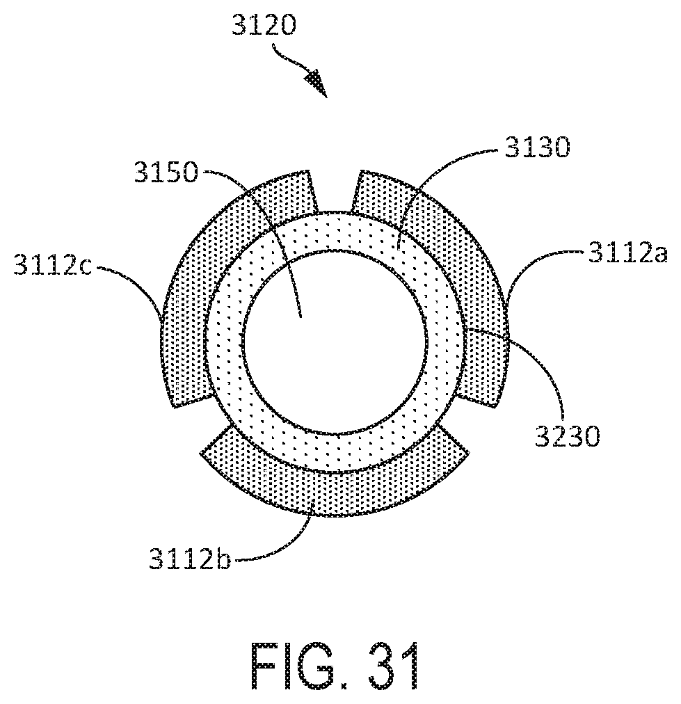
D00016

D00017

D00018

D00019

D00020

D00021

D00022

D00023

D00024

D00025
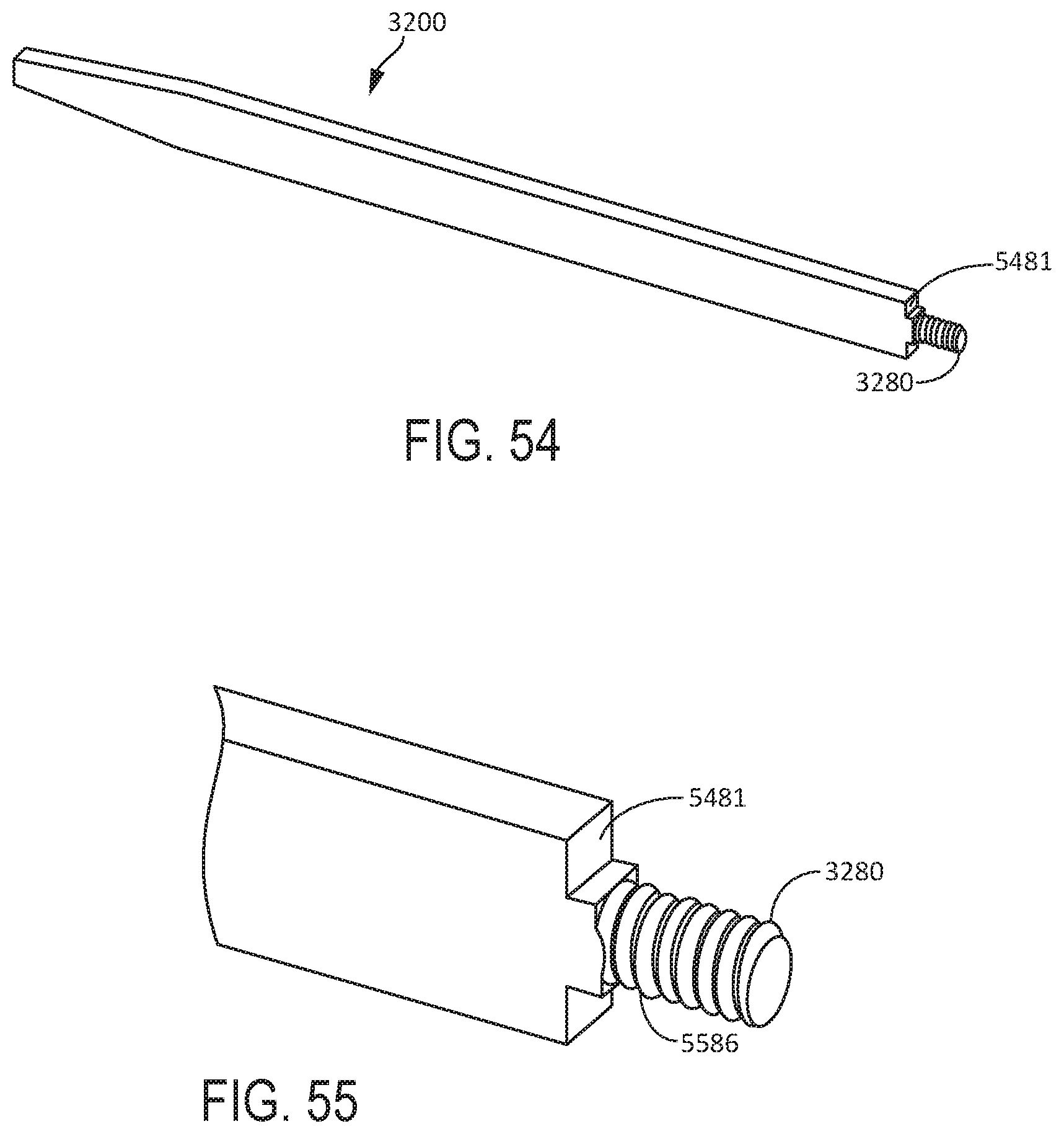
D00026
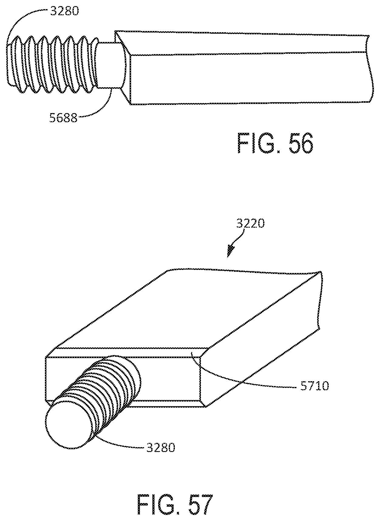
D00027

D00028

D00029

D00030
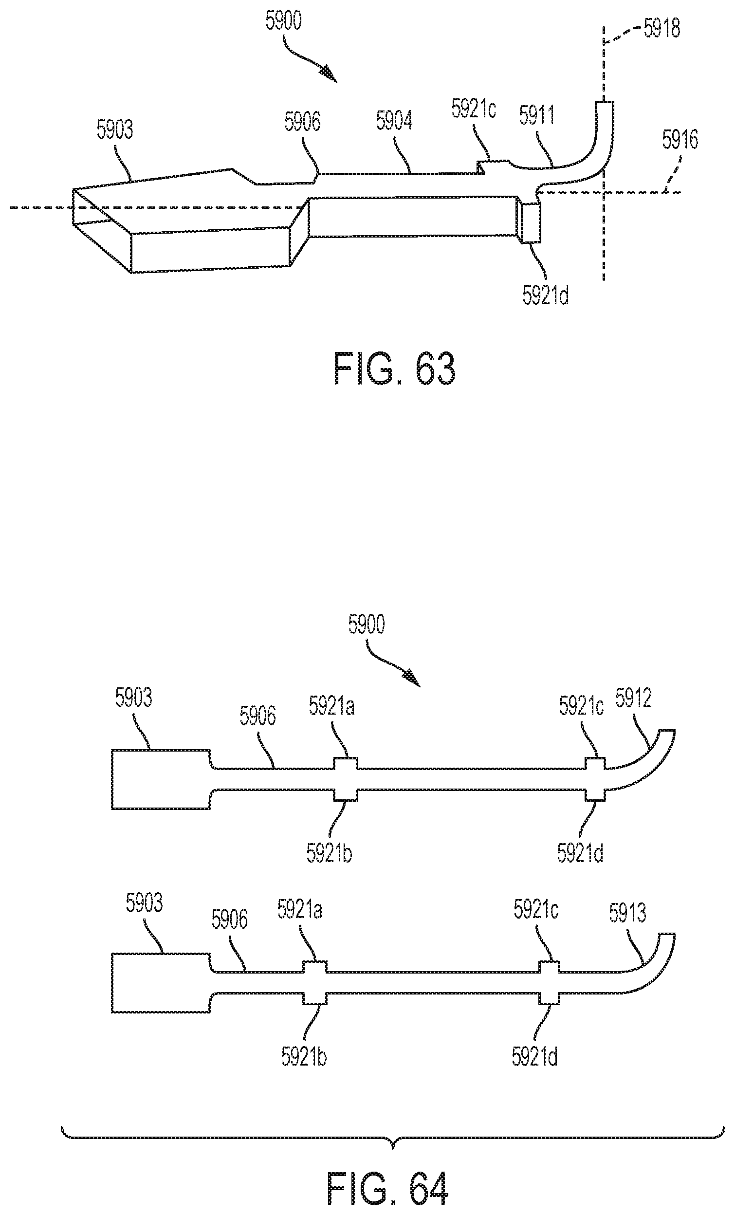
D00031
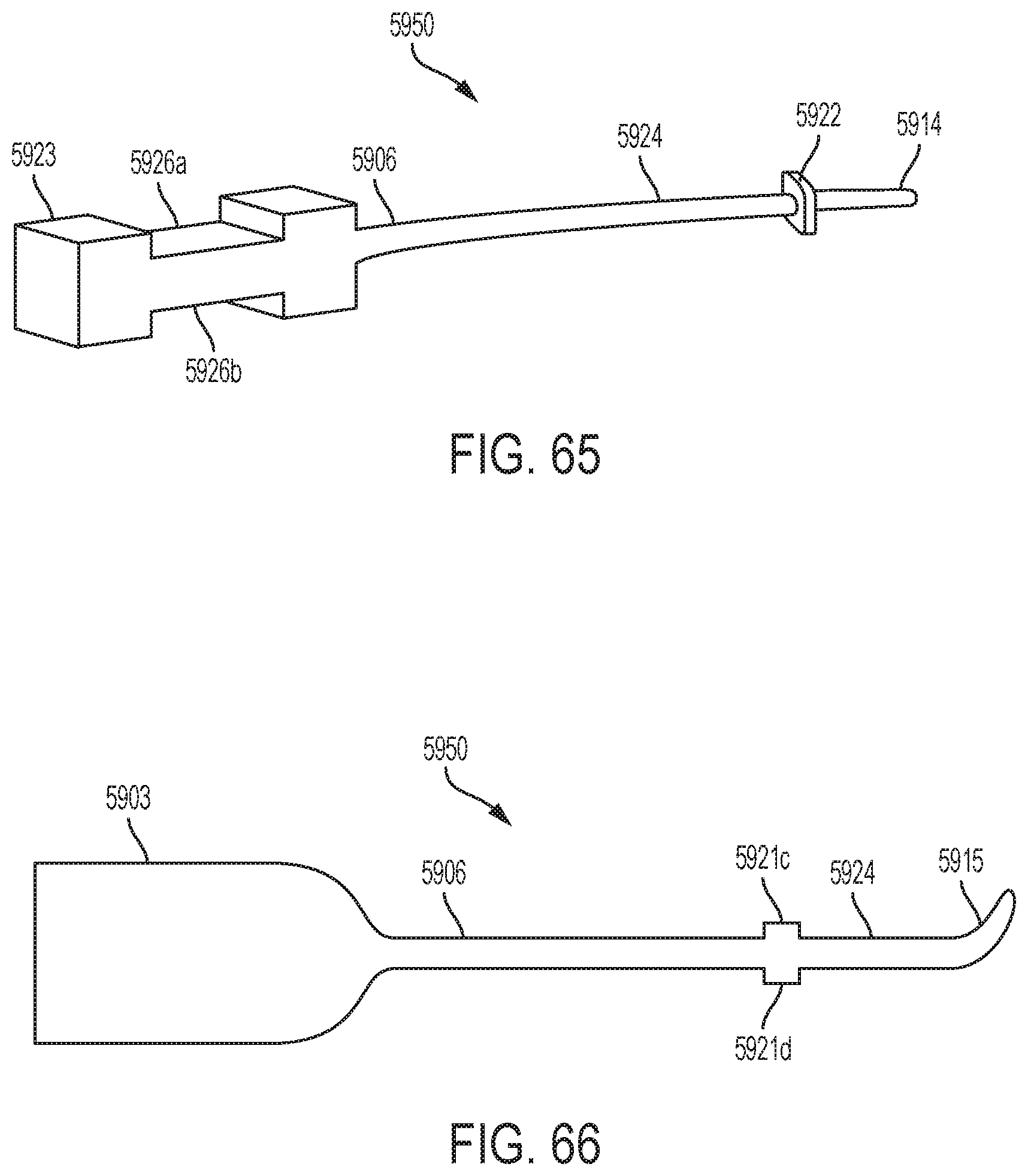

XML
uspto.report is an independent third-party trademark research tool that is not affiliated, endorsed, or sponsored by the United States Patent and Trademark Office (USPTO) or any other governmental organization. The information provided by uspto.report is based on publicly available data at the time of writing and is intended for informational purposes only.
While we strive to provide accurate and up-to-date information, we do not guarantee the accuracy, completeness, reliability, or suitability of the information displayed on this site. The use of this site is at your own risk. Any reliance you place on such information is therefore strictly at your own risk.
All official trademark data, including owner information, should be verified by visiting the official USPTO website at www.uspto.gov. This site is not intended to replace professional legal advice and should not be used as a substitute for consulting with a legal professional who is knowledgeable about trademark law.