Garment
YAMADA; Mitsuru ; et al.
U.S. patent application number 16/288411 was filed with the patent office on 2019-11-21 for garment. This patent application is currently assigned to DESCENTE LTD.. The applicant listed for this patent is DESCENTE LTD.. Invention is credited to Ryoko HATANAKA, Shosuke KUMAMOTO, Seitaro OCHIAI, Mitsuru YAMADA.
| Application Number | 20190350285 16/288411 |
| Document ID | / |
| Family ID | 68533369 |
| Filed Date | 2019-11-21 |

| United States Patent Application | 20190350285 |
| Kind Code | A1 |
| YAMADA; Mitsuru ; et al. | November 21, 2019 |
GARMENT
Abstract
Provided is a garment that is excellent in the stretchability of a fabric and a joining part between fabrics, and is comfortable to the wearer. Provided is a garment including a first fabric, a second fabric, and a belt-shaped member, in which the first fabric is in a back panel, the second fabric is in a front panel, the belt-shaped member is arranged along the first fabric and the second fabric, at least one of the first fabric and the second fabric has a larger elongation in a direction perpendicular to a direction parallel to a boundary line between the first fabric and the second fabric (boundary line perpendicular direction D2) than an elongation in the direction parallel to the boundary line (boundary line parallel direction), F.sub.x=L.sub.x{12k.sub.b1x.times.12k.sub.b2x/(12k.sub.b1x+12k.sub.b2x)+- 6k.sub.tx} F.sub.y=L.sub.y(3k.sub.b1y+3k.sub.b2y+k.sub.ty) F.sub.b1x=L.sub.b1x.times.6k.sub.b1x F.sub.b2x=L.sub.b2x.times.6k.sub.b2x F.sub.b1y=L.sub.b1y.times.6k.sub.b1y F.sub.b2y=L.sub.b2y.times.6k.sub.b2y the k.sub.tx and k.sub.ty that are solutions of the above equations have a relationship of k.sub.tx>k.sub.ty, and the k.sub.b1x, k.sub.b1y, k.sub.b2x, and k.sub.b2y that are solutions of the above equations have a relationship of at least one of k.sub.b1x<k.sub.b1y and k.sub.b2x<k.sub.b2y.
| Inventors: | YAMADA; Mitsuru; (Osaka, JP) ; KUMAMOTO; Shosuke; (Osaka, JP) ; HATANAKA; Ryoko; (Osaka, JP) ; OCHIAI; Seitaro; (Osaka, JP) | ||||||||||
| Applicant: |
|
||||||||||
|---|---|---|---|---|---|---|---|---|---|---|---|
| Assignee: | DESCENTE LTD. Osaka JP |
||||||||||
| Family ID: | 68533369 | ||||||||||
| Appl. No.: | 16/288411 | ||||||||||
| Filed: | February 28, 2019 |
| Current U.S. Class: | 1/1 |
| Current CPC Class: | A41H 43/04 20130101; A41D 31/185 20190201; A41D 2300/52 20130101; A41D 27/245 20130101; A41D 2500/10 20130101; A41D 31/18 20190201; A41D 2200/20 20130101 |
| International Class: | A41D 31/18 20060101 A41D031/18 |
Foreign Application Data
| Date | Code | Application Number |
|---|---|---|
| May 16, 2018 | JP | 2018-094941 |
Claims
1. A garment comprising: a first fabric; a second fabric; and a belt-shaped member, wherein the first fabric is in a back panel and the second fabric is in a front panel, the belt-shaped member is arranged along the first fabric and the second fabric, at least one of the first fabric and the second fabric has a larger elongation in a direction perpendicular to a direction parallel to a boundary line between the first fabric and the second fabric (hereinafter, also referred to as "boundary line perpendicular direction") than an elongation in the direction parallel to the boundary line (hereinafter, also referred to as "boundary line parallel direction"), F.sub.x=L.sub.x{12k.sub.b1x.times.12k.sub.b2x/(12k.sub.b1x+12k.sub.b2x)+6- k.sub.tx} F.sub.y=L.sub.y(3k.sub.b1y+3k.sub.b2y+k.sub.ty) F.sub.b1x=L.sub.b1x.times.6k.sub.b1x F.sub.b2x=L.sub.b2x.times.6k.sub.b2x F.sub.b1y=L.sub.b1y.times.6k.sub.b1y F.sub.b2y=L.sub.b2y.times.6k.sub.b2y the k.sub.tx and k.sub.ty that are solutions of the above equations have a relationship of k.sub.tx>k.sub.ty, and the k.sub.b1x, k.sub.b1y, k.sub.b2x, and k.sub.b2y that are solutions of the above equations have a relationship of at least one of k.sub.b1x<k.sub.b1y and k.sub.b2x<k.sub.b2y: in the above equations, F.sub.x represents a load (N) applied in the boundary line perpendicular direction to a part in which the first fabric and the second fabric are laminated to the belt-shaped member (hereinafter, also referred to as "laminated part"), L represents a displacement (mm) when a load is applied to the laminated part in the boundary line perpendicular direction, F.sub.y represents a load (N) applied to the laminated part in the boundary line parallel direction, L.sub.y represents a displacement (mm) when a load is applied to the laminated part in the boundary line parallel direction, F.sub.b1x represents a load (N) applied to the first fabric in the boundary line perpendicular direction, L.sub.b1x represents a displacement (mm) when a load is applied to the first fabric in the boundary line perpendicular direction, F.sub.b2x represents a load (N) applied to the second fabric in the boundary line perpendicular direction, L.sub.b2x represents a displacement (mm) when a load is applied to the second fabric in the boundary line perpendicular direction, F.sub.b1y represents a load (N) applied to the first fabric in the boundary line parallel direction, L.sub.b1y represents a displacement (mm) when a load is applied to the first fabric in the boundary line parallel direction, F.sub.b2y represents a load (N) applied to the second fabric in the boundary line parallel direction, and L.sub.b2y represents a displacement (mm) when a load is applied to the second fabric in the boundary line parallel direction, respectively.
2. The garment according to claim 1, wherein the k.sub.tx, k.sub.b1x and k.sub.b2x that are solutions of the above equations have a relationship of at least one of k.sub.tx>k.sub.b1x, and k.sub.tx>k.sub.b2x.
3. The garment according to claim 1, wherein the k.sub.tx and k.sub.ty that are solutions of the above equations have a ratio of 1.5 or more, provided that the ratio of the k.sub.tx and k.sub.ty that are solutions of the above equations=k.sub.tx/k.sub.ty.
4. The garment according to claim 1, wherein at least one of the first fabric and the second fabric has a ratio of an elongation in the boundary line perpendicular direction to an elongation in the boundary line parallel direction of 1.5 or more, provided that the ratio of the elongation in the boundary line perpendicular direction to the elongation in the boundary line parallel direction=elongation [%] in the boundary line perpendicular direction/elongation [%] in the boundary line parallel direction.
5. A garment comprising: a first fabric; a second fabric; and a belt-shaped member, wherein the first fabric is in a back panel and the second fabric is in a front panel, at least one of the front panel and the back panel includes a fabric having a larger elongation than an elongation of at least one of the first fabric and the second fabric in a direction (hereinafter, also referred to as "boundary line perpendicular direction") perpendicular to a direction parallel to a boundary line between the first fabric and the second fabric (hereinafter, also referred to as "boundary line parallel direction") in at least a part of from a lower part of an armhole to a boundary between the first fabric and the second fabric, and the belt-shaped member is arranged along the armhole of at least one of the first fabric and the second fabric.
6. The garment according to claim 5, wherein at least one of the first fabric and the second fabric has a plurality of knit structures.
7. The garment according to claim 5, wherein the back panel includes a fabric having a larger elongation than an elongation of the first fabric in the boundary line perpendicular direction in a central part of the back panel.
8. The garment according to claim 5, wherein a longitudinal perpendicular direction extension part having a larger elongation in a longitudinal direction of a sleeve than an elongation in a direction perpendicular to the longitudinal direction of the sleeve is included in a part located in an elbow part when worn, and a longitudinal direction extension part having a larger elongation in a direction perpendicular to the longitudinal direction of the sleeve than an elongation in the longitudinal direction of the sleeve is included on both of upper and lower sides in the longitudinal direction of the sleeve in the longitudinal perpendicular direction extension part.
9. The garment according to claim 8, wherein the garment has a sleeve, the sleeve contains a rib knitting part, and a longitudinal direction of a furrow in the rib knitting part is non-parallel to an axial direction of the sleeve.
10. The garment according to claim 1, which is an outer garment or an intermediate garment.
11. The garment according to claim 1, wherein the first fabric and the second fabric are joined by welding, and the belt-shaped member is attached to the joining part.
12. The garment according to claim 5, which is an outer garment or an intermediate garment.
13. The garment according to claim 5, wherein the first fabric and the second fabric are joined by welding, and the belt-shaped member is attached to the joining part.
Description
CROSS-REFERENCE TO RELATED APPLICATIONS
[0001] The present application claims the benefit of priority to Japanese Patent Application Number 2018-94941 filed on May 16, 2018. The entire contents of the specification of Japanese Patent Application Number 2018-94941 filed on May 16, 2018 are hereby incorporated by reference.
FIELD OF THE INVENTION
[0002] The present invention relates to a garment, and particularly relates to a garment having a first fabric, a second fabric, and a belt-shaped member, in which the belt-shaped member is arranged along the first fabric and the second fabric.
DESCRIPTION OF RELATED ART
[0003] Conventionally, non-sewn clothing produced by joining multiple fabrics without using a thread and a needle and by not performing sewing (for example, see JP-A-2007-162196 and JP-A-2008-101304) is known. The non-sewn clothing as described above has an advantage that a broken needle is not mixed into the clothing because a needle is not used, and it is easy to produce the clothing because the fabrics are joined by bonding or welding.
PRIOR ART DOCUMENTS
Patent Documents
[0004] Patent document 1: Japanese Unexamined Patent Application Publication No. 2007-162196
[0005] Patent document 2: Japanese Unexamined Patent Application Publication No. 2008-101304
SUMMARY OF THE INVENTION
Problems to be Solved by the Invention
[0006] However, in the clothing having the structure as described in JP-A-2007-162196 or JP-A-2008-101304, the stretchability of a joining part between fabrics is poor, and thus the clothing may not sufficiently follow the body of the wearer in some cases. Therefore, there is a sense of discomfort due to the clothing being pulled or the like during exercise such as running or jumping, and it is considered that there is room for further improvement in the clothing. In addition, in the clothing having the structure as described in JP-A2007-162196 or JPA-2008-101304, the skin contact at a joining part between fabrics is poor, and thus clothing that is comfortable to the wearer has been demanded.
[0007] The present invention has been made in consideration of the above circumstances, and an object of the present invention is to provide a garment that is excellent in the stretchability of a fabric and a joining part between fabrics and is comfortable to the wearer.
Solution to the Problem
[0008] The garment according to the present invention, which has been able to solve the above problem, is a garment including a first fabric, a second fabric, and a belt-shaped member, in which the first fabric is in a back panel, the second fabric is in a front panel, the belt-shaped member is arranged along the first fabric and the second fabric, at least one of the first fabric and the second fabric has a larger elongation in a direction generally perpendicular (ie. 90.degree..+-.10.degree.) to a direction parallel to a boundary line between the first fabric and the second fabric (hereinafter, also referred to as "boundary line perpendicular direction") than an elongation in the direction parallel to the boundary line (hereinafter, also referred to as "boundary line parallel direction"),
F.sub.x=L.sub.x{12k.sub.b1x.times.12k.sub.b2x/(12k.sub.b1x+12k.sub.b2x)+- 6k.sub.tx}
F.sub.y=L.sub.y(3k.sub.b1y+3k.sub.b2y+k.sub.ty)
F.sub.b1x=L.sub.b1x.times.6k.sub.b1x
F.sub.b2x=L.sub.b2x.times.6k.sub.b2x
F.sub.b1y=L.sub.b1y.times.6k.sub.b1y
F.sub.b2y=L.sub.b2y.times.6k.sub.b2y
the k.sub.tx and k.sub.ty that are solutions of the above equations have a relationship of k.sub.tx>k.sub.ty, and the k.sub.b1x, k.sub.b1y, k.sub.b2x, and k.sub.b2y that are solutions of the above equations have a relationship of at least one of k.sub.b1x<k.sub.b1y and k.sub.b2x<k.sub.b2y.
[0009] In the above equations, F.sub.x represents a load (N) applied in the boundary line perpendicular direction to a part in which the first fabric and the second fabric are laminated to the belt-shaped member (hereinafter, also referred to as "laminated part"), L.sub.x represents a displacement (mm) when a load is applied to the laminated part in the boundary line perpendicular direction, F.sub.y represents a load (N) applied to the laminated part in the boundary line parallel direction, L.sub.y represents a displacement (mm) when a load is applied to the laminated part in the boundary line parallel direction, F.sub.b1x represents a load (N) applied to the first fabric in the boundary line perpendicular direction, L.sub.b1x represents a displacement (mm) when a load is applied to the first fabric in the boundary line perpendicular direction, F.sub.b2x represents a load (N) applied to the second fabric in the boundary line perpendicular direction, L.sub.b2x represents a displacement (mm) when a load is applied to the second fabric in the boundary line perpendicular direction, F.sub.b1y represents a load (N) applied to the first fabric in the boundary line parallel direction, L.sub.b1y represents a displacement (mm) when a load is applied to the first fabric in the boundary line parallel direction, F.sub.b2y represents a load (N) applied to the second fabric in the boundary line parallel direction, and L.sub.b2y represents a displacement (mm) when a load is applied to the second fabric in the boundary line parallel direction, respectively.
[0010] In the garment described above, the k.sub.tx, k.sub.b1x and k.sub.b2x that are solutions of the above equations preferably have a relationship of at least one of k.sub.tx>k.sub.b1x and k.sub.tx>k.sub.b2x.
[0011] In the garment described above, the k.sub.tx and k.sub.ty that are solutions of the above equations preferably have a ratio of 1.5 or more, provided that the ratio of the k.sub.tx and k.sub.ty that are solutions of the above equations=k.sub.tx/k.sub.ty.
[0012] In the garment described above, at least one of the first fabric and the second fabric preferably has a ratio of an elongation in the boundary line perpendicular direction to an elongation in the boundary line parallel direction of 1.5 or more, provided that the ratio of the elongation in the boundary line perpendicular direction to the elongation in the boundary line parallel direction=elongation [%] in the boundary line perpendicular direction/elongation [%] in the boundary line parallel direction.
[0013] In addition, the garment according to the present invention, which has been able to solve the above problem, is a garment including a first fabric, a second fabric, and a belt-shaped member, in which the first fabric is in a back panel, the second fabric is in a front panel, at least one of the front panel and the back panel includes a fabric having a larger elongation than an elongation of at least one of the first fabric and the second fabric in a direction (hereinafter, also referred to as "boundary line perpendicular direction") perpendicular to a direction parallel to a boundary line between the first fabric and the second fabric (hereinafter, also referred to as "boundary line parallel direction") in at least a part of from a lower part of an armhole to a boundary between the first fabric and the second fabric, and the belt-shaped member is arranged along the armhole of at least one of the first fabric and the second fabric.
[0014] In the garment described above, at least one of the first fabric and the second fabric preferably has a plurality of knit structures.
[0015] In the garment described above, the back panel preferably includes a fabric having a larger elongation than an elongation of the first fabric in the boundary line perpendicular direction in a central part of the back panel.
[0016] In the garment described above, it is preferred that a longitudinal perpendicular direction extension part having a larger elongation in a longitudinal direction of a sleeve than an elongation in a direction perpendicular to the longitudinal direction of the sleeve is included in a part located in an elbow part when worn, and a longitudinal direction extension part having a larger elongation in a direction perpendicular to the longitudinal direction of the sleeve than an elongation in the longitudinal direction of the sleeve is included on both of upper and lower sides in the longitudinal direction of the sleeve in the longitudinal perpendicular direction extension part.
[0017] In the garment described above, it is preferred that the garment has a sleeve, the sleeve contains a rib knitting part, and a longitudinal direction of a furrow in the rib knitting part is non-parallel to an axial direction of the sleeve.
[0018] In the garment described above, the garment is preferably an outer garment or an intermediate garment.
[0019] In the garment described above, it is preferred that the first fabric and the second fabric are joined by welding, and the belt-shaped member is attached to the joining part.
Effects of the Invention
[0020] The garment according to a first aspect of the present invention is a garment including a first fabric, a second fabric, and a belt-shaped member, in which the first fabric is in a back panel, the second fabric is in a front panel, the belt-shaped member is arranged along the first fabric and the second fabric, at least one of the first fabric and the second fabric has a larger elongation in a direction substantially perpendicular (ie. 90.degree..+-.10.degree.) to a direction parallel to a boundary line between the first fabric and the second fabric (hereinafter, also referred to as "boundary line perpendicular direction") than an elongation in the direction parallel to the boundary line (hereinafter, also referred to as "boundary line parallel direction"),
F.sub.x=L.sub.x{12k.sub.b1x.times.12k.sub.b2x/(12k.sub.b1x+12k.sub.b2x)+- 6k.sub.tx}
F.sub.y=L.sub.y(3k.sub.b1y+3k.sub.b2y+k.sub.ty)
F.sub.b1x=L.sub.b1x.times.6k.sub.b1x
F.sub.b2x=L.sub.b2x.times.6k.sub.b2x
F.sub.b1y=L.sub.b1y.times.6k.sub.b1y
F.sub.b2y=L.sub.b2y.times.6k.sub.b2y
the k.sub.tx and k.sub.ty that are solutions of the above equations have a relationship of k.sub.tx>k.sub.ty, and the k.sub.b1x, k.sub.b1y, k.sub.b2x, and k.sub.b2y that are solutions of the above equations have a relationship of at least one of k.sub.b1x<k.sub.b1y and k.sub.b2x<k.sub.b2y, By constituting the garment in such a way, a garment can be provided in which not only the fabrics constituting the garment but also a boundary part between the first fabric and the second fabric are excellent in the stretchability, and in particular, which is comfortable to the wearer during exercise.
[0021] The garment according to a second aspect of the present invention is a garment including a first fabric, a second fabric, and a belt-shaped member, in which the first fabric is in a back panel, the second fabric is in a front panel, at least one of the front panel and the back panel includes a fabric having a larger elongation than an elongation of at least one of the first fabric and the second fabric in a direction (hereinafter, also referred to as "boundary line perpendicular direction") generally perpendicular (ie. 90.degree..+-.10.degree.) to a direction parallel to a boundary line between the first fabric and the second fabric (hereinafter, also referred to as "boundary line parallel direction") in at least a part of from a lower part of an armhole to a boundary between the first fabric and the second fabric, and the belt-shaped member is arranged along the armhole of at least one of the first fabric and the second fabric. By constituting the garment in such a way, a garment can be provided which is excellent in the stretchability, has favorable skin contact in a joining part between fabrics in an armhole part of the garment, and is comfortable to the wearer.
BRIEF DESCRIPTION OF THE DRAWINGS
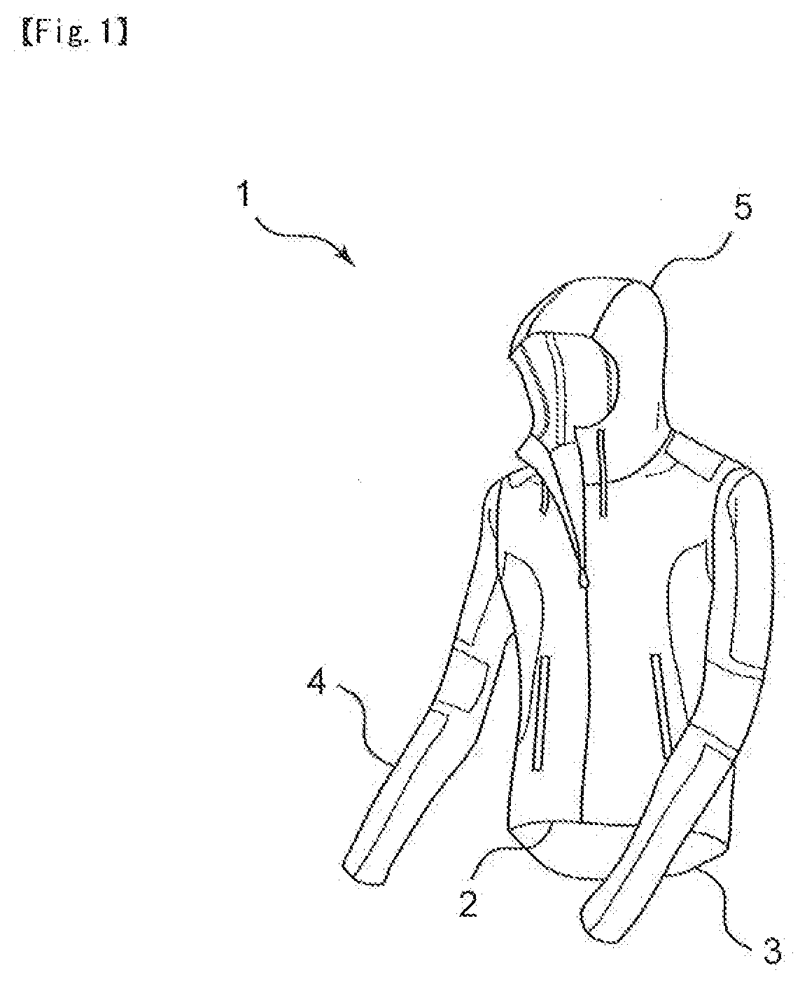
[0022] FIG. 1 shows an overall view of a garment according to the present invention as viewed from the front side;
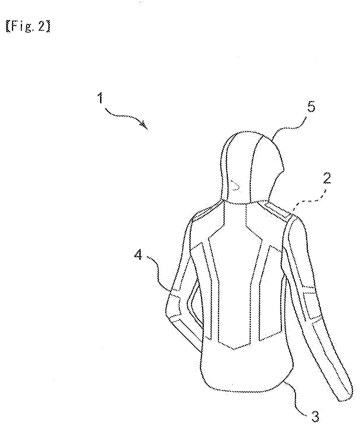
[0023] FIG. 2 shows an overall view of the garment according to the present invention as viewed from the back side;
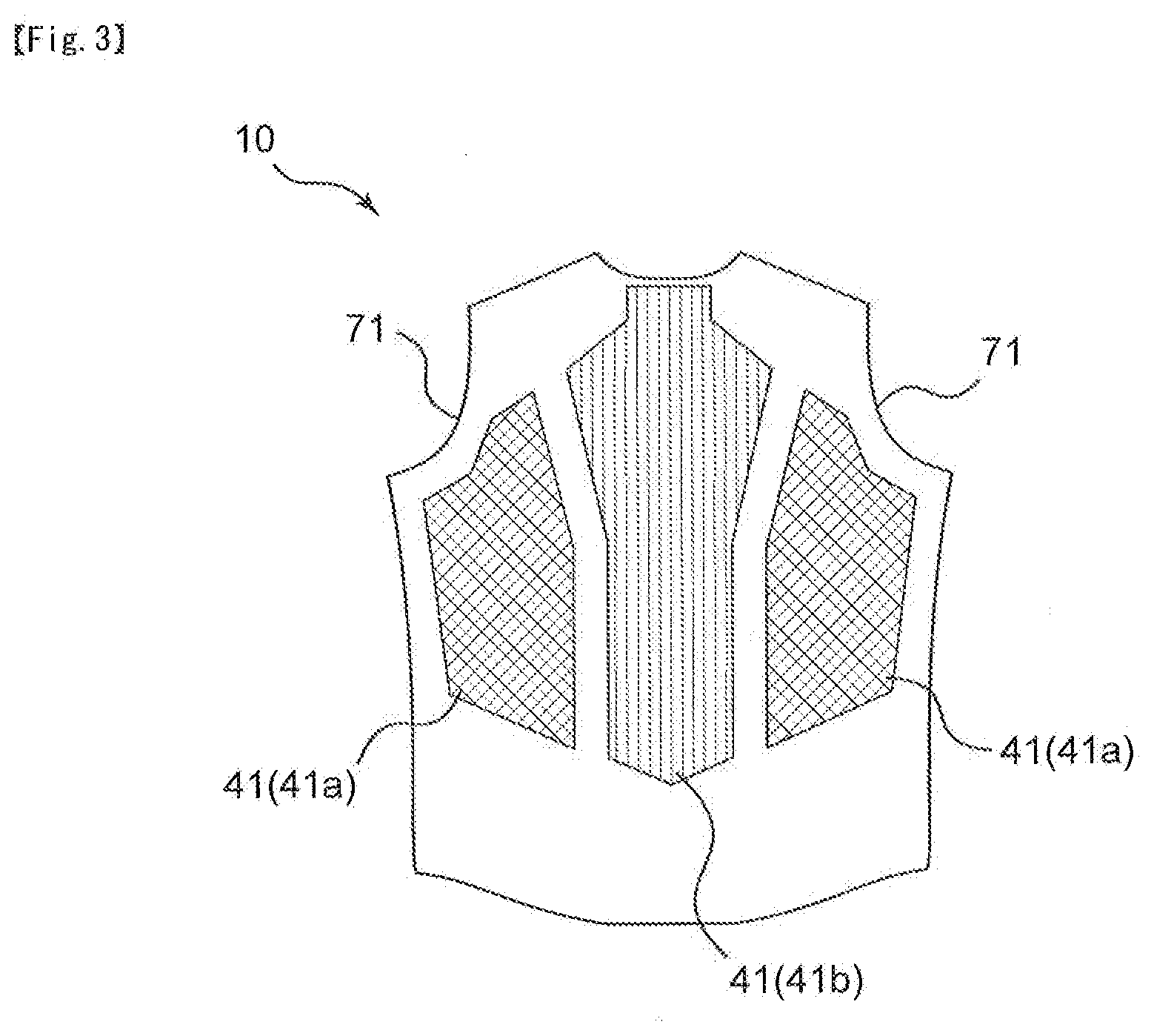
[0024] FIG. 3 shows a plan view of a first fabric in the garment according to the present invention;
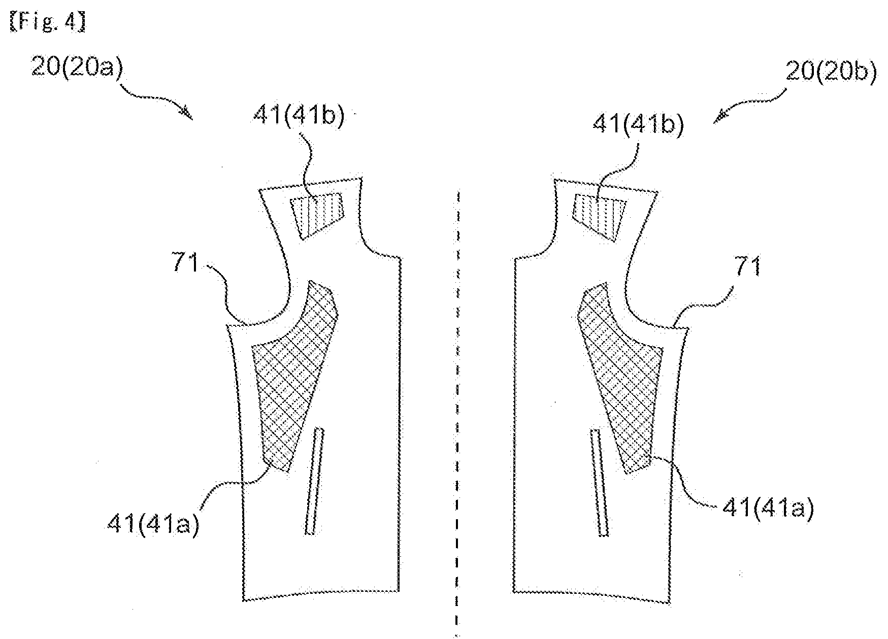
[0025] FIG. 4 shows a plan view of a second fabric in the garment according to the present invention;
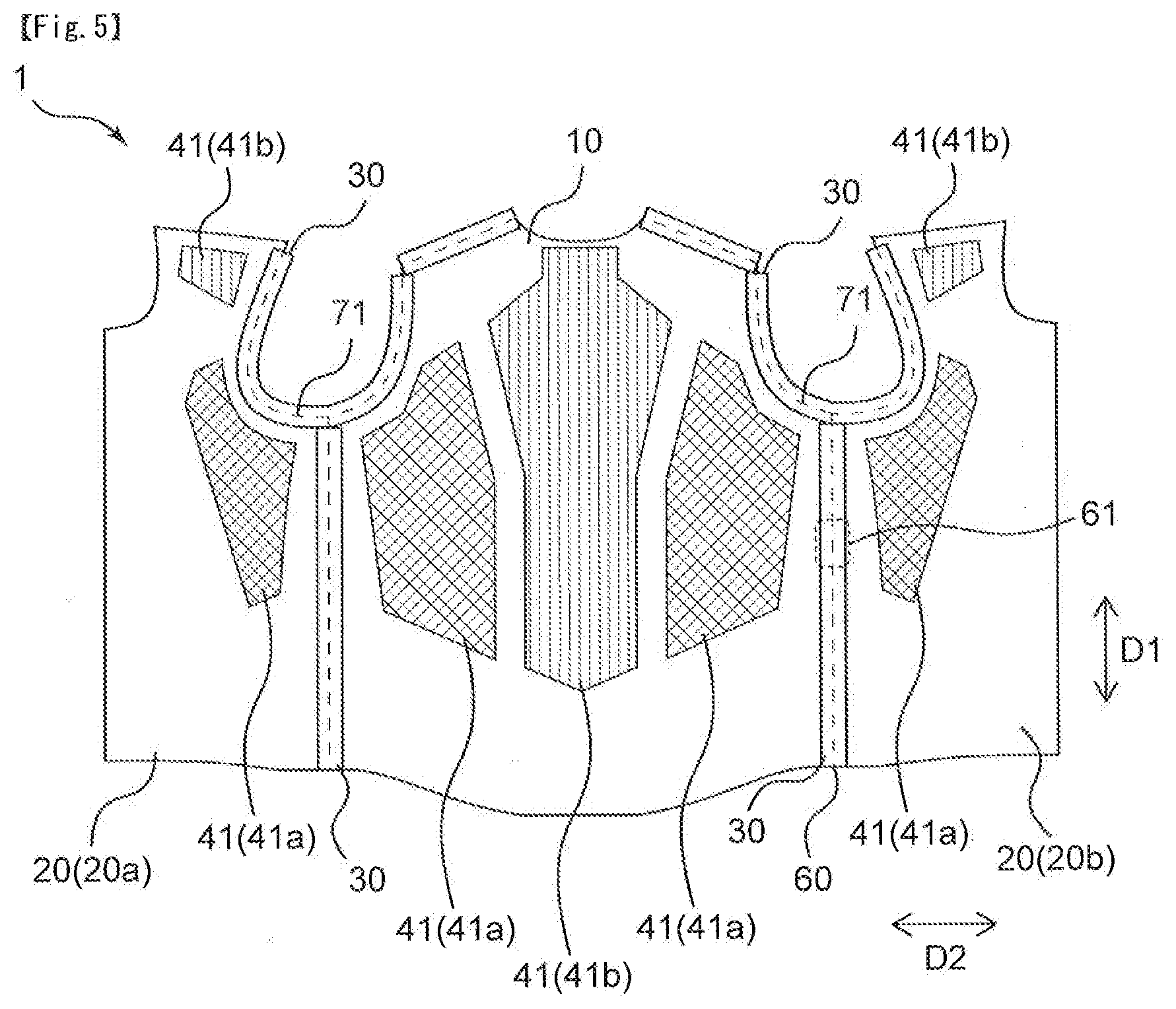
[0026] FIG. 5 shows a development view of the garment according to the present invention as viewed from the wearer side;
[0027] FIG. 6 shows a plan view of a fabric constituting a sleeve in the garment according to the present invention;
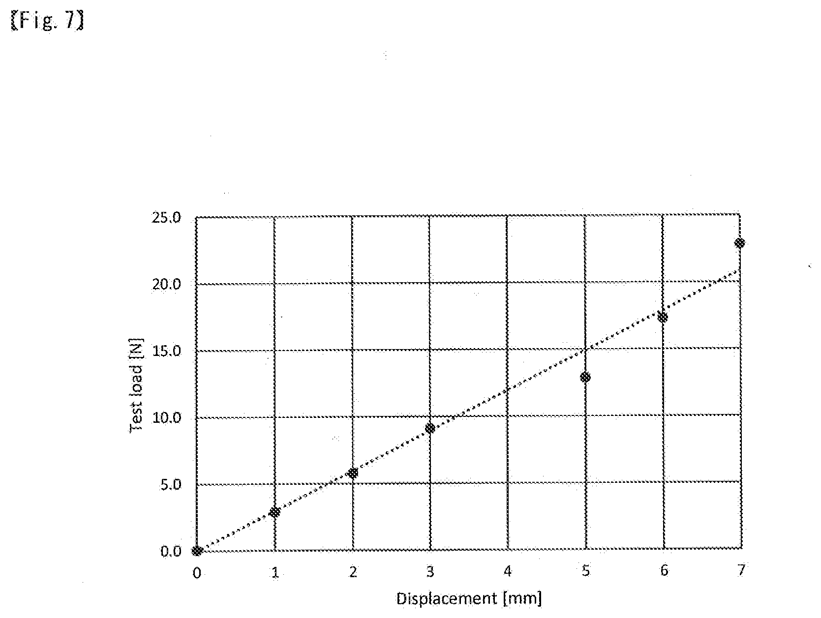
[0028] FIG. 7 shows a graph showing a displacement when a load is applied to a first fabric in a boundary line parallel direction;
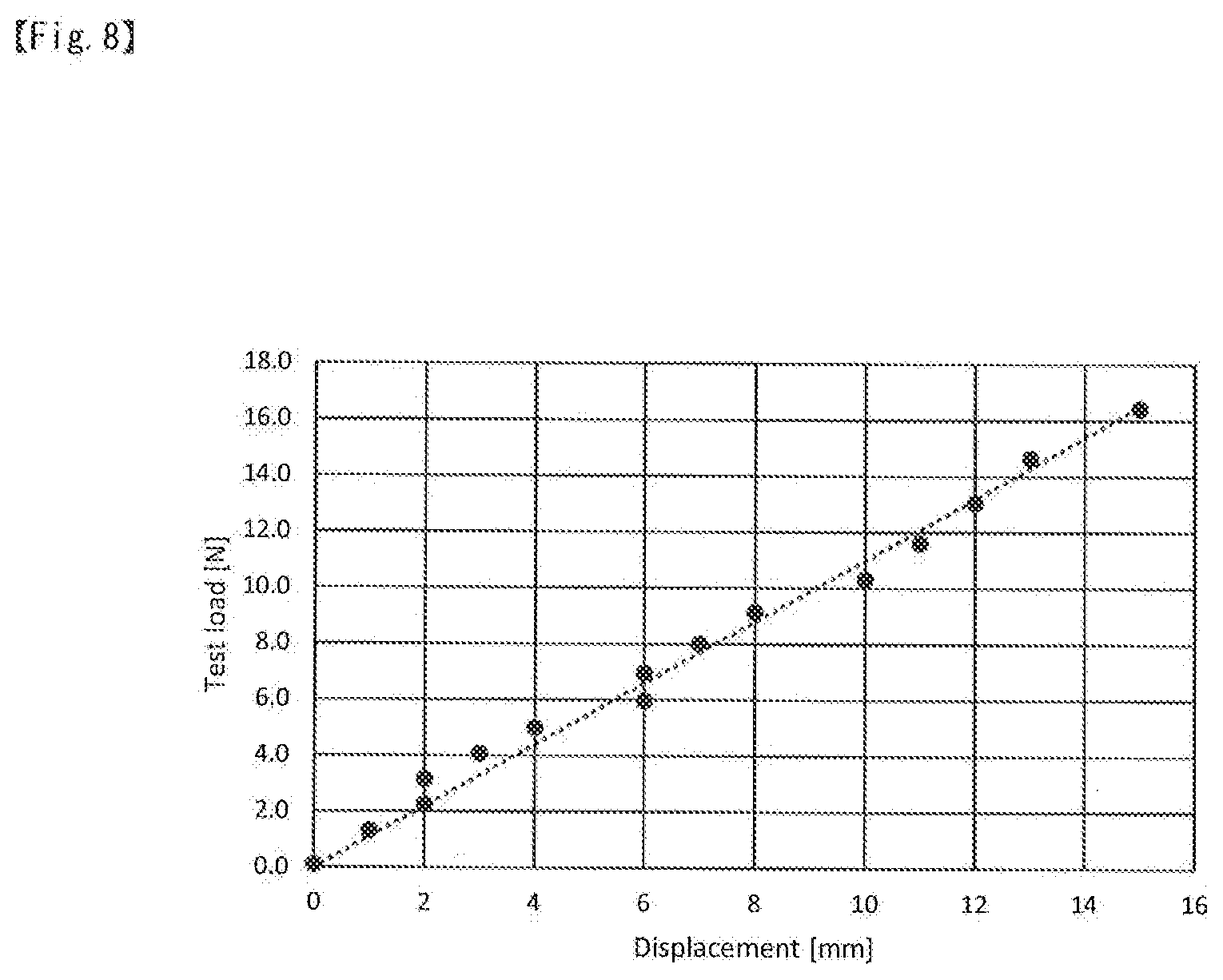
[0029] FIG. 8 shows a graph showing a displacement when a load is applied to a first fabric in a boundary line perpendicular direction;
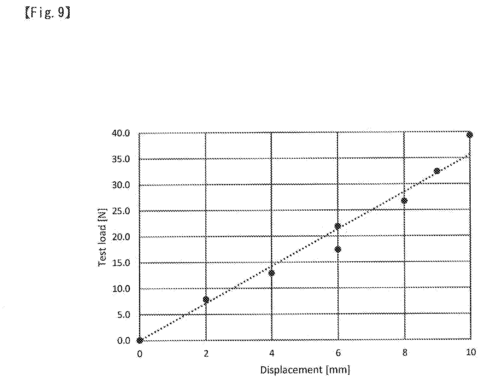
[0030] FIG. 9 shows a graph showing a displacement when a load is applied to a laminated fabric in a boundary line parallel direction; and
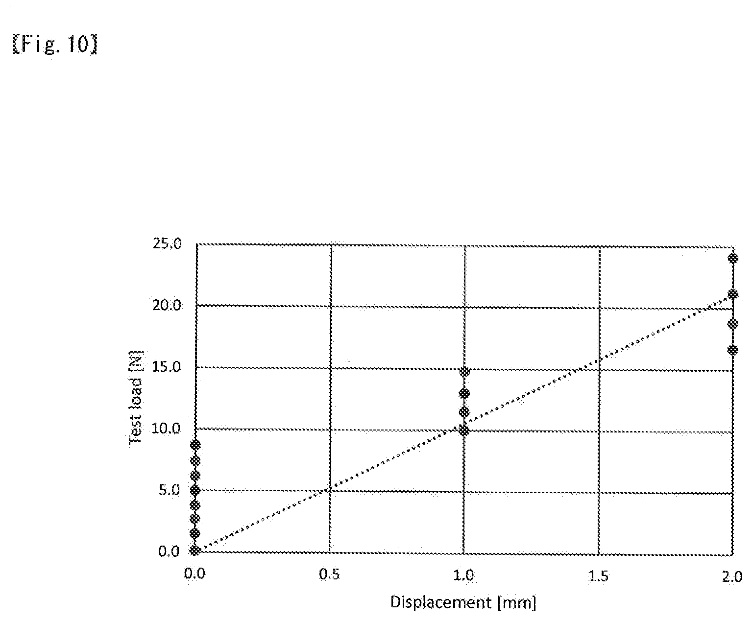
[0031] FIG. 10 shows a graph showing a displacement when a load is applied to a laminated fabric in a boundary line perpendicular direction.
DETAILED DESCRIPTION OF THE PREFERRED EMBODIMENTS
Embodiment 1
[0032] Hereinafter, a garment according to an embodiment 1 of the present invention will be described more specifically with reference to the drawings; however, the present invention is not originally limited by the following embodiments, and can be performed, of course, with the addition of appropriate modifications in a range capable of conforming to the preceding and following gists, and all of the modified inventions are included in the technical scope of the present invention. In addition, sizes of various members in the drawings may be different from the actual sizes in some cases because the sizes are given priority in contributing to an understanding of the features of the present invention.
[0033] The present invention relates to a garment. FIG. 1 shows an overall view of a garment 1 as viewed from the front side, and FIG. 2 shows an overall view of a garment 1 as viewed from the back side. The garment 1 has a front panel 2 and a back panel 3, and may include a part to be worn at least on the upper body, or may include a part to be worn at least on the lower body. In a case where the garment 1 includes a part to be worn on the upper body, the garment 1 may have, for example, a sleeve 4 in addition to the front panel 2 and the back panel 3, and may also have a hood 5 attached to the garment 1. The front panel 2 and the back panel 3 mean parts that cover the front side and back side of the body, respectively, and the front panel 2 and the back panel 3 are partitioned by the side of the body.
[0034] In the present invention, the outer surface side of the garment 1 means the outside air side as viewed from the wearer when the garment 1 is worn. The skin surface side of the garment 1 means the wearer side opposite to the outer surface side.
[0035] The garment 1 according to a first aspect of the present invention is a garment 1 including a first fabric 10, a second fabric 20, and a belt-shaped member 30, and is characterized in that the first fabric 10 is in a back panel 3, the second fabric 20 is in a front panel 2, the belt-shaped member 30 is arranged along the first fabric 10 and the second fabric 20, at least one of the first fabric 10 and the second fabric 20 has a larger elongation in a direction perpendicular to a direction parallel to a boundary line between the first fabric 10 and the second fabric 20 (hereinafter, also referred to as "boundary line perpendicular direction D2") than an elongation in the direction parallel to the boundary line between the first fabric 10 and the second fabric 20 (hereinafter, also referred to as "boundary line parallel direction D1"),
F.sub.x=L.sub.x{12k.sub.b1x.times.12k.sub.b2x/(12k.sub.b1x+12k.sub.b2x)+- 6k.sub.tx}
F.sub.y=L.sub.y(3k.sub.b1y+3k.sub.b2y+k.sub.ty)
F.sub.b1x=L.sub.b1x.times.6k.sub.b1x
F.sub.b2x=L.sub.b2x.times.6k.sub.b2x
F.sub.b1y=L.sub.b1y.times.6k.sub.b1y
F.sub.b2y=L.sub.b2y.times.6k.sub.b2y
the k.sub.tx and k.sub.ty that are solutions of the above equations have a relationship of k.sub.tx>k.sub.ty, and the k.sub.b1x, k.sub.b1y, k.sub.b2x, and k.sub.b2y that are solutions of the above equations have a relationship of at least one of k.sub.b1x<k.sub.b1y and k.sub.b2x<k.sub.b2y.
[0036] In the above equations, F.sub.x represents a load (N) applied in the boundary line perpendicular direction D2 to a part in which the first fabric 10 and the second fabric 20 are laminated to the belt-shaped member 30 (hereinafter, also referred to as "laminated part 61"), L.sub.x represents a displacement (mm) when a load is applied to the laminated part 61 in the boundary line perpendicular direction D2, F.sub.y represents a load (N) applied to the laminated part 61 in the boundary line parallel direction D1, L.sub.y represents a displacement (mm) when a load is applied to the laminated part 61 in the boundary line parallel direction D1, F.sub.b1x represents a load (N) applied to the first fabric 10 in the boundary line perpendicular direction D2, L.sub.b1x represents a displacement (mm) when a load is applied to the first fabric 10 in the boundary line perpendicular direction D2, F.sub.b2x represents a load (N) applied to the second fabric 20 in the boundary line perpendicular direction D2, L.sub.b2x represents a displacement (mm) when a load is applied to the second fabric 20 in the boundary line perpendicular direction D2, F.sub.b1y represents a load (N) applied to the first fabric 10 in the boundary line parallel direction D1, L.sub.b1y represents a displacement (mm) when a load is applied to the first fabric 10 in the boundary line parallel direction D1, F.sub.b2y represents a load (N) applied to the second fabric 20 in the boundary line parallel direction D1, and L.sub.b2y represents a displacement (mm) when a load is applied to the second fabric 20 in the boundary line parallel direction D1, respectively.
[0037] The F.sub.x, F.sub.y, F.sub.b1x, F.sub.b2x, F.sub.b1y, and F.sub.b2y are preferably the loads up to the maximum elongation in a load-elongation curve drawn with the load on the vertical axis and the elongation on the horizontal axis, which is a relationship between the load applied to the laminated part 61, the first fabric 10, and the second fabric 20 in each of the boundary line perpendicular direction D12 and the boundary line parallel direction D1 and the elongation of the laminated part 61, the first fabric 10, and the second fabric 20 when each of the loads is applied. By setting the values of the F.sub.x, F.sub.y, F.sub.b1x, F.sub.b2x, F.sub.b1y, and F.sub.b2y in this way, each of the values of k.sub.tx, k.sub.ty, k.sub.b1x, k.sub.b1y, k.sub.b2x, and k.sub.b2y can be calculated accurately.
[0038] The F.sub.x, F.sub.y, F.sub.b1x, F.sub.b2x, F.sub.b1y, and F.sub.b2y are preferably the loads in a region of initial deformation in which a load and a displacement are proportional to each other in a load-elongation curve drawn with the load on the vertical axis and the elongation on the horizontal axis, which is a relationship between the load applied to the laminated part 61, the first fabric 10, and the second fabric 20 in each of the boundary line perpendicular direction 1D2 and the boundary line parallel direction D1 and the elongation of the laminated part 61, the first fabric 10, and the second fabric 20 when each of the loads is applied. That is, the F.sub.x, F.sub.y, F.sub.b1x, F.sub.b2x, F.sub.b1y, and F.sub.b2y are preferably the values in a region of initial deformation in which a load and a displacement are proportional to each other in each sample. By setting the values of the F.sub.x, F.sub.y, F.sub.b1x, F.sub.b2x, F.sub.b1y, and F.sub.b2y in this way, the k.sub.tx, k.sub.ty, k.sub.b1x, k.sub.b1y, k.sub.b2x, and k.sub.b2y can be compared more precisely.
[0039] The F.sub.x, F.sub.y, F.sub.b1x, F.sub.b2x, F.sub.b1y, and F.sub.b2y may be the same values as each other. That is, the L.sub.x, L.sub.y, L.sub.b1x, L.sub.b2x, L.sub.b1y, and L.sub.b2y may be respective displacements when the same load is applied to the laminated part 61, the first fabric 10, and the second fabric 20 in each of the boundary line perpendicular direction D2 and the boundary line parallel direction D1. When the sizes of respective samples of the laminated part 61, the first fabric 10, and the second fabric 20 are the same as each other and the values of the F.sub.x, F.sub.y, F.sub.b1x, F.sub.b2x, F.sub.b1y, and F.sub.b2y are the same values as each other, the displacement can be measured without changing the setting, conditions, or the like of a testing machine according to each sample, so that the measurement of each displacement becomes easy.
[0040] The garment 1 includes the first fabric 10, the second fabric 20, and the belt-shaped member 30. FIG. 3 shows a plan view of the first fabric 10, FIG. 4 shows a plan view of the second fabric 20, and FIG. 5 shows a development view of the garment 1 as viewed from the wearer side. In this regard, the expression "development view of the garment 1 as viewed from the wearer side" is referred to as a development view on the skin surface side of the garment 1. As shown in FIGS. 3 and 5, the first fabric 10 is in the back panel 3. As shown in FIGS. 4 and 5, the second fabric 20 is in the front panel 2. The second fabric 20 may include a second fabric 20a on the right side in a right front panel, and a second fabric 20b on the left side in a left front panel.
[0041] As the kind of the first fabric 10, for example, a woven fabric of a plain weave, a twill weave, a satin weave, or the like; a knit fabric of plain knitting, rib knitting, garter knitting, or the like; a nonwoven fabric; or the like can be mentioned. Among them, the first fabric 10 is preferably a knit fabric, and more preferably a knit fabric of rib knitting. By constituting the first fabric 10 in this way, the stretchability of the first fabric 10 can be enhanced.
[0042] The first fabric 10 may have multiple knit structures or weave structures. As a specific example, a constitution in which different kinds of knit structures such as rib knitting and mesh knitting are included in the first fabric 10, or the like can be mentioned. By including multiple knit structures or weave structures in the first fabric 10, the characteristics can be changed by a part of the first fabric 10. For example, the whole knit structure of the first fabric 10 is formed by rib knitting, so that the whole stretchability of the first fabric 10 is enhanced, and the first fabric 10 is fitted to the body of the wearer. The knit structure in the vicinity of the side of the first fabric 10 is formed by mesh knitting, so that the air-permeability in the vicinity of the side in which heat is easy to be accumulated is enhanced, and the wear comfort of the garment 1 can be improved.
[0043] Examples of the material for the fiber constituting the first fabric 10 include a synthetic fiber such as polyester, polyurethane, and nylon; and a natural fiber such as cotton and hemp. Among them, the material for the fiber constituting the first fabric 10 is preferably a synthetic fiber, and more preferably polyester. By constituting the first fabric 10 in this way, the joining strength with the belt-shaped member 30 can be enhanced, and the garment 1 is easily produced.
[0044] The thickness of the first fabric 10 is preferably 0.5 mm or more, more preferably 0.7 mm or more, furthermore preferably 1 mm or more, and particularly preferably 1.2 mm or more. By setting the lower limit value of the thickness of the first fabric 10 in this way, the joining strength with the belt-shaped member 30 is enhanced, and the strength of a joining part 60 can be enhanced. The upper limit value of the thickness of the first fabric 10 is not particularly limited, and can be set to be, for example, 10 mm or less, 5 mm or less, or 3 mm or less. In this regard, the thickness of the first fabric 10 is obtained by measuring the thicknesses in arbitrary multiple parts of the first fabric 10, and then by averaging the obtained multiple values of the thickness.
[0045] As the kind of the second fabric 20, a woven fabric, a knit fabric, a nonwoven fabric, or the like can be mentioned, as in the case of the kind of the first fabric 10, and among them, the second fabric 20 is preferably a knit fabric, and more preferably a knit fabric of rib knitting. By constituting the second fabric 20 in this way, the second fabric 20 having the favorable stretchability can be obtained. In addition, the second fabric 20 may have multiple knit structures or weave structures, as in the case of the first fabric 10.
[0046] Examples of the material for the fiber constituting the second fabric 20 include a synthetic fiber and a natural fiber as in the case of the material for the fiber constituting the first fabric 10, and among them, the material is preferably a synthetic fiber, and preferably polyester. By constituting the second fabric 20 in this way, the joining strength between the second fabric 20 and the belt-shaped member 30 is enhanced, and the second fabric 20 and the belt-shaped member 30 is easily joined.
[0047] The thickness of the second fabric 20 is, as in the case of the thickness of the first fabric 10, preferably 0.5 mm or more, more preferably 0.7 mm or more, furthermore preferably 1 mm or more, and particularly preferably 1.2 mm or more. By setting the lower limit value of the thickness of the second fabric 20 in this way, the joining strength between the second fabric 20 and the belt-shaped member 30 can be enhanced, and the strength of the joining part 60 can be increased. The upper limit value of the thickness of the second fabric 20 is not also particularly limited, as in the case of the first fabric 10, and can be set to be, for example, 10 mm or less, 5 mm or less, or 3 mm or less. In this regard, the thickness of the second fabric 20 is obtained by measuring the thicknesses in arbitrary multiple parts of the second fabric 20, and then by averaging the obtained multiple values of the thickness.
[0048] The first fabric 10 and the second fabric 20 may be fabrics of different kinds or materials, but are preferably fabrics of the same kind or material. By using the same kind or material for the first fabric 10 and the second fabric 20, the physical properties of the first fabric 10 and the second fabric 20 are equalized, and a joining step of the first fabric 10 and the second fabric 20 is easily performed. In addition, the first fabric 10 and the second fabric 20 are preferably knit fabrics of synthetic fiber, and more preferably rib knitting of polyester. By constituting the first fabric 10 and the second fabric 20 in this way, the garment 1 that is excellent in the stretchability and has the joining part 60 with high strength can be obtained.
[0049] As the kind of the belt-shaped member 30, a woven fabric of a plain weave, a twill weave, a satin weave, or the like; a knit fabric of plain knitting, rib knitting, garter knitting, or the like; a nonwoven fabric; or a material obtained by coating these fabrics with a synthetic resin can be mentioned. Among them, the kind of the belt-shaped member 30 is preferably a knit fabric. By forming the belt-shaped member 30 with a knitted fabric, the stretchability can be imparted to the belt-shaped member 30, and the stretchability can also be imparted to the joining part 60. In addition, because the belt-shaped member 30 has favorable skin touch, the garment 1 that is comfortable to the wearer can be obtained.
[0050] Examples of the material for the fiber constituting the belt-shaped member 30 include a synthetic fiber such as polyester, polyurethane, and nylon; and a natural fiber such as cotton and hemp. Among them, the material for the fiber constituting the belt-shaped member 30 is preferably a synthetic fiber, and more preferably polyurethane. By constituting the belt-shaped member 30 in this way, the joining strength with the first fabric 10 and the second fabric 20 is increased, and the productivity of the garment 1 can be enhanced. In addition, the stretchability of the belt-shaped member 30 can also be enhanced.
[0051] As shown in FIG. 5, the belt-shaped member 30 is arranged along the first fabric 10 and the second fabric 20. That is, the belt-shaped member 30 is joined to both of the first fabric 10 and the second fabric 20, and the first fabric 10 and the second fabric 20 are joined to each other with the belt-shaped member 30. By joining the first fabric 10 and the second fabric 20 with the belt-shaped member 30, as compared with a garment sewn with a thread and a needle or a garment joined by welding, the surface state of the joining part 60 between the first fabric 10 and the second fabric 20 becomes a smooth state with little unevenness, and the skin contact to the wearer of the garment 1 is improved.
[0052] The boundary between the first fabric 10 and the second fabric 20 is preferably located in a central part of the belt-shaped member 30, The expression "central part" of the belt-shaped member 30 is referred to as the center region of the width of belt-shaped member 30 divided into three equal regions. By arranging the first fabric 10 and the second fabric 20 in such a position of the belt-shaped member 30, the joining strength between the first fabric 10 and the belt-shaped member 30 as well as the joining strength between the second fabric 20 and the belt-shaped member 30 can be enhanced, and the garment 1 that has favorable production efficiency and excellent durability can be obtained.
[0053] As shown in FIG. 5, it is preferred to provide the belt-shaped member 30 at a position on the boundary between the front panel 2 and the back panel 3 in the side part, at a position on the boundary between the front panel 2 and the back panel 3 in the shoulder part, and at a position of an armhole 71. By providing the belt-shaped member 30 at these positions, the garment 1 that has favorable skin contact and is comfortable to the wearer can be obtained.
[0054] At least one of the first fabric 10 and the second fabric 20 has a larger elongation in a direction perpendicular to a direction parallel to a boundary line between the first fabric 10 and the second fabric 20 (boundary line perpendicular direction D2) than an elongation in the direction parallel to the boundary line between the first fabric 10 and the second fabric 20 (boundary line parallel direction D1). That is, at least one of the first fabric 10 and the second fabric 20 has a larger elongation in a circumferential direction of the body of the wearer than an elongation in a vertical direction that is a direction from the head to the foot of the wearer. By constituting at least one of the first fabric 10 and the second fabric 20 in this way, the garment 1 that is easily fitted to the body of the wearer is obtained. In the present invention, "perpendicular" means 80 degrees-100 degrees. It is not necessary to have the larger elongation in the boundary line perpendicular direction D2 than in the boundary line parallel direction D1 in all of 80 degrees-100 degrees, and the larger elongation in the boundary line perpendicular direction D2 than in the boundary line parallel direction D1 at an angle of the identification of 80 degrees-100 degrees.
[0055] It is sufficient that at least one of the first fabric 10 and the second fabric 20 has a larger elongation in the boundary line perpendicular direction D2 than an elongation in the boundary line parallel direction D1; however, it is preferred that the first fabric 10 and the second fabric 20 have a larger elongation in the boundary line perpendicular direction D2 than an elongation in the boundary line parallel direction D1. By constituting the first fabric 10 and the second fabric 20 in this way, the stretchability of the garment 1 can be further enhanced, and the garment 1 becomes easy to follow the motion of the body of the wearer.
[0056] In the garment 1, the k.sub.tx and k.sub.ty that are solutions of the following equations have a relationship of k.sub.tx>k.sub.ty. In addition, the k.sub.b1x, k.sub.b1y, k.sub.b2x, and k.sub.b2y that are solutions of the following equations have a relationship of at least one of k.sub.b1x<k.sub.b1y and k.sub.b2x<k.sub.b2y.
F.sub.x=L.sub.x{12k.sub.b1x.times.12k.sub.b2x/(12k.sub.b1x+12k.sub.b2x)+- 6k.sub.tx}
F.sub.y=L.sub.y(3k.sub.b1y+3k.sub.b2y+k.sub.ty)
F.sub.b1x=L.sub.b1x.times.6k.sub.b1x
F.sub.b2x=L.sub.b2x.times.6k.sub.b2x
F.sub.b1y=L.sub.b1y.times.6k.sub.b1y
F.sub.b2y=L.sub.b2y.times.6k.sub.b2y
[0057] In the above equations, F.sub.x represents a load (N) applied in the boundary line perpendicular direction D2 to a part in which the first fabric 10 and the second fabric 20 are laminated to the belt-shaped member 30 (laminated part 61), L.sub.x represents a displacement (mm) when a load is applied to the laminated part 61 in the boundary line perpendicular direction D2, F.sub.y represents a load (N) applied to the laminated part 61 in the boundary line parallel direction D1, L.sub.y represents a displacement (mm) when a load is applied to the laminated part 61 in the boundary line parallel direction D1, F.sub.b1x represents a load (N) applied to the first fabric 10 in the boundary line perpendicular direction D2, L.sub.b1x represents a displacement (mm) when a load is applied to the first fabric 10 in the boundary line perpendicular direction D2, F.sub.b2x represents a load (N) applied to the second fabric 20 in the boundary line perpendicular direction D2, L.sub.2x represents a displacement (mm) when a load is applied to the second fabric 20 in the boundary line perpendicular direction D2, F.sub.b1y represents a load (N) applied to the first fabric 10 in the boundary line parallel direction D1, L.sub.b1y represents a displacement (mm) when a load is applied to the first fabric 10 in the boundary line parallel direction D1, F.sub.b2y represents a load (N) applied to the second fabric 20 in the boundary line parallel direction D1, and L.sub.b2y represents a displacement (mm) when a load is applied to the second fabric 20 in the boundary line parallel direction D1, respectively.
[0058] After the measurement of L.sub.x, L.sub.y, L.sub.b1x, L.sub.b2x, L.sub.b1y, and L.sub.b2y, the k.sub.tx, k.sub.ty, k.sub.b1x, k.sub.b1y, k.sub.b2x, and k.sub.b2y that are solutions of the above equations are calculated, and a relationship between the k.sub.tx and the k.sub.ty, a relationship between the k.sub.b1x and the k.sub.b1y, and a relationship between the k.sub.b2x and the k.sub.b2y are determined.
[0059] By having the fact that the k.sub.tx and k.sub.ty that are solutions of the above equations satisfy a relationship of k.sub.tx>k.sub.ty, and that the k.sub.b1x, k.sub.b1y, k.sub.b2x, and k.sub.b2y satisfy a relationship of at least one of k.sub.b1x<k.sub.b1y and k.sub.b2x<k.sub.b2y, the garment 1 that is excellent in the stretchability in the boundary part between the first fabric 10 and the second fabric 20, easy to follow the motion of the body of the wearer, and comfortable during exercise can be obtained.
[0060] In addition, when a garment is made without sewing, in order to make the garment beautifully finished, it is required to apply tension to a fabric at the time of joining the fabric. If a fabric having a high elongation is used in order to obtain a garment having excellent stretchability, the fabric is excessively elongated in the joining step of each fabric, and it may be difficult to obtain a beautiful finish or may be insufficient in the joining of each fabric. The k.sub.tx and k.sub.ty have a relationship of k.sub.tx>k.sub.ty, whereas the k.sub.b1x, k.sub.b1y, k.sub.b2x, and k.sub.b2y have a relationship of at least one of k.sub.b17<k.sub.b1y and k.sub.b2x<k.sub.b2y, so that the belt-shaped member 30 prevents the first fabric 10 and the second fabric 20 from being excessively elongated, the joining strength with the first fabric 10 and the second fabric 20 is enhanced, and the production efficiency of the garment 1 can be increased.
[0061] It is sufficient that the k.sub.b1x, k.sub.b1y, k.sub.b2x, and k.sub.b2y have a relationship of at least one of k.sub.b1x<k.sub.b1y and k.sub.b2x<k.sub.b2y; however, it is preferred to have a relationship of k.sub.b1x<k.sub.b1y and k.sub.b2x<k.sub.b2y. By having the fact that the k.sub.b1x, k.sub.b1y, k.sub.b2x, and k.sub.b2y satisfy such a relationship, the stretchability in the boundary part between the first fabric 10 and the second fabric 20 can be enhanced, and the garment 1 is easily fitted to the body of the wearer. In addition, also in the joining step of the first fabric 10 and the belt-shaped member 30 as well as the second fabric 20 and the belt-shaped member 30, the joining is easily performed, and the productivity of the garment 1 can be enhanced.
[0062] In a case where the garment 1 has a hood 5, the hood 5 is constituted of multiple fabrics, and the belt-shaped member 30 is preferably arranged along the boundary between the fabrics. That is, the belt-shaped member 30 is joined to each of the fabrics constituting the hood 5, and each of the fabrics constituting the hood 5 is preferably joined to each other with the belt-shaped member 30. By constituting the hood 5 with multiple fabrics, the hood 5 is easily fitted to the head of the wearer. By arranging the belt-shaped member 30 along the boundary between the fabrics constituting the hood 5, even when the hood 5 is fitted to the head of the wearer, the surface of the joining part between the fabrics constituting the hood 5 becomes smooth, and a sense of discomfort is hardly given to the wearer.
[0063] In a case where the garment 1 has the hood 5, the belt-shaped member 30 is preferably arranged along the boundary between the hood 5 and the first fabric 10. That is, the fabric constituting the hood 5 and the first fabric 10 are preferably joined by the belt-shaped member 30. By arranging the belt-shaped member 30 along the boundary between the hood 5 and the first fabric 10, unevenness is hardly formed in the joining part between the hood 5 and the first fabric 10, and the garment 1 that has favorable skin contact can be obtained.
[0064] In a case where the garment 1 has the second fabric 20a on the right side in a right front panel and the second fabric 20b on the left side in a left front panel, the garment 1 may have an engagement member engaging the second fabric 20a on the right side with the second fabric 20b on the left side. Examples of the engagement member include a zip fastener, and a hook and loop fastener. In addition, the engagement member may be provided, for example, in an opening of a pocket or the like of the garment 1. As the method for joining the engagement member to the first fabric 10 or the second fabric 20, for example, sewing, welding by ultrasonic waves or heat, bonding by an adhesive, or the like can be mentioned. Among them, as the method for joining the engagement member, sewing is preferred. By joining the engagement member to the first fabric 10 or the second fabric 20 by sewing, the bonding strength between the engagement member and the first fabric 10 or second fabric 20 can be enhanced. Therefore, even if stress is applied to the joining part between the engagement member and the first fabric 10 or the second fabric 20 at the time of engaging or separating the engagement member, the engagement member is hardly removed from the first fabric 10 or the second fabric 20.
[0065] In this regard, in the joining part between the engagement member and the first fabric 10 or the second fabric 20, it is preferred to arrange a belt-shaped member 30. By arranging the belt-shaped member 30 in the joining part between the engagement member and the first fabric 10 or the second fabric 20, the surface of the joining part of the engagement member is made smooth, and the joining part of the engagement member hardly gives a sense of discomfort to the body of the wearer.
[0066] The k.sub.tx k.sub.b1x and k.sub.b2x that are solutions of the above equations preferably have a relationship of at least one of k.sub.tx>k.sub.b1x and k.sub.tx>k.sub.b2x. By having the fact that the k.sub.tx, k.sub.b1x and k.sub.b2x satisfy such a relationship, the stretchability of the garment 1 is improved, and the garment 1 that hardly hinders the motion of the body of the wearer during exercise can be obtained. In addition, also in the production of the garment 1, the joining part 60 between the first fabric 10 and the second fabric 20 is prevented from being excessively elongated, and the production efficiency of the garment 1 can be enhanced.
[0067] In addition, the k.sub.tx, k.sub.b1x and k.sub.b2x preferably have a relationship of k.sub.tx>k.sub.b1x and k.sub.tx>k.sub.b2x. By having the fact that the k.sub.tx, k.sub.b1x and k.sub.b2x satisfy such a relationship, the stretchability of the garment 1 can be further enhanced, and the garment 1 becomes easy to follow the body of the wearer.
[0068] The k.sub.tx and k.sub.ty that are solutions of the above equations have preferably a ratio of 1.5 or more, more preferably a ratio of 1.7 or more, and furthermore preferably a ratio of 2 or more. In this regard, the ratio of the k.sub.tx and k.sub.ty is calculated by a calculation formula of k.sub.tx/k.sub.ty. By setting the lower limit value of the ratio of the k.sub.tx and k.sub.ty in this way, the stretchability in the joining part 60 is enhanced, and the garment 1 that is easy to follow the body of the wearer can be obtained. The upper limit value of the ratio of the k.sub.tx and k.sub.ty is not particularly limited, and can be set to be, for example, 10 or less, 8 or less, or 5 or less.
[0069] At least one of the first fabric 10 and the second fabric 20 has a ratio of an elongation in the boundary line perpendicular direction D2 to an elongation in the boundary line parallel direction D1 of preferably 1.5 or more, more preferably 1.7 or more, and furthermore preferably 2 or more. In this regard, the ratio of an elongation of the first fabric 10 in the boundary line perpendicular direction D2 to an elongation of the first fabric 10 in the boundary line parallel direction D1 is calculated by a calculation formula of the elongation [%] of the first fabric 10 in the boundary line perpendicular direction D2/the elongation [%] of the first fabric 10 in the boundary line parallel direction D1, and the ratio of an elongation of the second fabric 20 in the boundary line perpendicular direction D2 to an elongation of the second fabric 20 in the boundary line parallel direction D1 is calculated by a calculation formula of the elongation [%] of the second fabric 20 in the boundary line perpendicular direction D2/the elongation [%] of the second fabric 20 in the boundary line parallel direction D. By setting the lower limit value of the ratio of the elongation of at least one of the first fabric 10 and the second fabric 20 in the boundary line perpendicular direction D2 to the elongation of at least one of the first fabric 10 and the second fabric 20 in the boundary line parallel direction D1 in this way, the garment 1 becomes easy to follow the motion of exercise or the like when the garment 1 is worn. The upper limit value of the ratio of the elongation of at least one of the first fabric 10 and the second fabric 20 in the boundary line perpendicular direction D2 to the elongation of at least one of the first fabric 10 and the second fabric 20 in the boundary line parallel direction D1 is not particularly limited, but can be set to be, for example, 1.0 or less, 8 or less, or 5 or less.
Embodiment 2
[0070] Hereinafter, a garment according to an embodiment 2 of the present invention will be described with reference to the drawings. Basically, the garment according to the embodiment 2 has a constitution similar to the constitution of the garment according to the embodiment 1, and therefore, the description of the common parts will be omitted.
[0071] The garment 1 of the embodiment 2 of the present invention is a garment 1 including a first fabric 10, a second fabric 20, and a belt-shaped member 30, and is characterized in that the first fabric 10 is in a back panel 3, the second fabric 20 is in a front panel 2, at least one of the front panel 2 and the back panel 3 includes a fabric having a larger elongation than an elongation of at least one of the first fabric 10 and the second fabric 20 in a direction (hereinafter, also referred to as "boundary line perpendicular direction D12") perpendicular to a direction parallel to a boundary line between the first fabric 10 and the second fabric 20 (hereinafter, also referred to as "boundary line parallel direction D1") in at least a part of from a lower part of an armhole 71 to a boundary between the first fabric 10 and the second fabric 20, and the belt-shaped member 30 is arranged along the armhole 71 of at least one of the first fabric 10 and the second fabric 20,
[0072] As shown in FIG. 5, at least one of the front panel 2 and the back panel. 3 includes a fabric 41 having a larger elongation than the elongation of at least one of the first fabric 10 and the second fabric 20 in the boundary line perpendicular direction D2, in at least the part of from the lower part of the armhole 71 to the boundary between the first fabric 10 and the second fabric 20. The lower part of the armhole 71 of the garment 1 is a part in which stress is easily applied to the fabric by the motion such as swinging the arms during exercise such as jogging. Therefore, by including the fabric 41 having a larger elongation than the elongation of at least one of the first fabric 10 and the second fabric 20 in the boundary line perpendicular direction D2, in at least the part of from the lower part of the armhole 71 of the garment 1 to the boundary between the first fabric 10 and the second fabric 20, the fabric in the lower part of the armhole 71 is prevented from being pulled during the exercise with the motion such as swinging the arms, and thus the wear comfort of the garment 1 can be enhanced.
[0073] The fabric 41 having a larger elongation than the elongation of at least one of the first fabric 10 and the second fabric 20 in the boundary line perpendicular direction D12 preferably has a larger elongation than an elongation of each of the first fabric 10 and the second fabric 20 in the boundary line perpendicular direction D2. By constituting the fabric 41 having a larger elongation than the elongation of at least one of the first fabric 10 and the second fabric 20 in the boundary line perpendicular direction D2 in this way, the stretchability of the armhole 71 can be further enhanced, and the wear comfort of the garment 1 during exercise can be enhanced.
[0074] As the method for forming the fabric 41 having a larger elongation than the elongation of at least one of the first fabric 10 and the second fabric 20 in the boundary line perpendicular direction D2, for example, a method of forming a knit structure or weave structure having higher stretchability than the stretchability of at least one of the first fabric 10 and the second fabric 20, a method of using a material having higher stretchability than the stretchability of at least one of the first fabric 10 and the second fabric 20, or the like can be mentioned.
[0075] The fabric 41 having a larger elongation than the elongation of at least one of the first fabric 10 and the second fabric 20 in the boundary line perpendicular direction D2 may be joined to at least one of the first fabric 10 in the back panel 3 and the second fabric 2 in the front panel 2 by welding, sewing, or the like, and it is preferred that the fabric 41 having a larger elongation than the elongation of at least one of the first fabric 10 and the second fabric 20 in the boundary line perpendicular direction D2 is included in the fabric constituting at least one of the first fabric 10 and the second fabric 20, by partially changing the knit structure or weave structure of at least one of the first fabric 10 and the second fabric 20. That is, the fabric 41 having a larger elongation than the elongation of at least one of the first fabric 10 and the second fabric 20 in the boundary line perpendicular direction D2, and at least one of the first fabric 10 and the second fabric 20 are preferably integrally constituted. By constituting the fabric 41 having a larger elongation than the elongation of at least one of the first fabric 10 and the second fabric 20 in the boundary line perpendicular direction D2 and at least one of the first fabric 10 and the second fabric 20 in this way, unevenness or the like due to the joining is hardly formed in the boundary part of the fabric 41 having a larger elongation than the elongation of at least one of the first fabric 10 and the second fabric 20 in the boundary line perpendicular direction D2, and therefore, the garment 1 that has favorable skin contact can be obtained.
[0076] The fabric 41 having a larger elongation than the elongation of at least one of the first fabric 10 and the second fabric 20 in the boundary line perpendicular direction D2 preferably has higher air-permeability than the air-permeability of at least one of the first fabric 10 and the second fabric 20. Since heat is easy to be accumulated between the fabric in the lower part of the armhole 71 and the wearer, for example, use of a fabric 41a having higher air-permeability than the air-permeability of at least one of the first fabric 10 and the second fabric 20, such as a mesh knit fabric, as the fabric 41 having a larger elongation than the elongation of at least one of the first fabric 10 and the second fabric 20 in the boundary line perpendicular direction D2 can improve the wear comfort of the garment 1.
[0077] The belt-shaped member 30 is arranged along the armhole 71 of at least one of the first fabric 10 and the second fabric 20. Since the armhole 71 is a part that comes into contact with the side of the wearer, particularly, it is required to improve the skin contact in this part. By arranging the belt-shaped member 30 along the armhole 71 of at least one of the first fabric 10 and the second fabric 20, the surface of the armhole 71 is made smooth, and the garment 1 that is comfortable to the wearer can be obtained.
[0078] The first fabric 10 and the second fabric 20 preferably have knit structures different from each other. By forming the knit structures of the first fabric 10 and the second fabric 20 different from each other, a function suitable for each part of the garment 1 can be imparted. For example, since heat is easy to be accumulated in a back part of an upper garment that is the garment 1, use of a knit structure having high air-permeability such as mesh knitting for the first fabric 10 in the back panel 3 can be mentioned.
[0079] At least one of the first fabric 10 and the second fabric 20 preferably has multiple knit structures. Specifically, for example, a constitution in which multiple different kinds of knit structures such as rib knitting and mesh knitting are included in the first fabric 10 can be mentioned. By including multiple knit structures in at least one of the first fabric 10 and the second fabric 20, adequate characteristics can be imparted to each part of the first fabric 10 or the second fabric 20. For example, by forming the whole knit structure of the first fabric 10 with rib knitting, the whole stretchability of the first fabric 10 is enhanced, and the first fabric 10 is fitted to the body of the wearer, and further, by forming the knit structure in the vicinity of the side of the first fabric 10 with mesh knitting, the air-permeability in the vicinity of the side in which heat is easy to be accumulated is enhanced, and thus the wear comfort of the garment 1 can be improved.
[0080] It is preferred that at least one of the first fabric 10 and the second fabric 20 has multiple knit structures, and it is more preferred that each of the first fabric 10 and the second fabric 20 has multiple knit structures, By including multiple knit structures in each of the first fabric 10 and the second fabric 20, a function that is required in each part in the whole body of the wearer can be imparted, and a more functional garment can be obtained as the garment 1.
[0081] A fabric 41b having a larger elongation than the elongation of the first fabric 10 in the boundary line perpendicular direction D2 is preferably included in the central part of the back panel. By constituting the back panel 3 in this way, the stretchability in the back part of an upper garment that is the garment 1 is enhanced, and the upper garment that is fitted to the wearer can be obtained.
[0082] The fabric 41b having a larger elongation than the elongation of the first fabric 10 in the boundary line perpendicular direction D2 may be arranged in a shoulder part of the second fabric 20. By constituting the second fabric 20 in this way, the stretchability can be imparted to the fabric in the shoulder part of the front panel 2, which is easily pulled according to the pulling of fabric at the time of motion such as turning the arm, and thus the garment 1 that has favorable wearing feeling can be obtained.
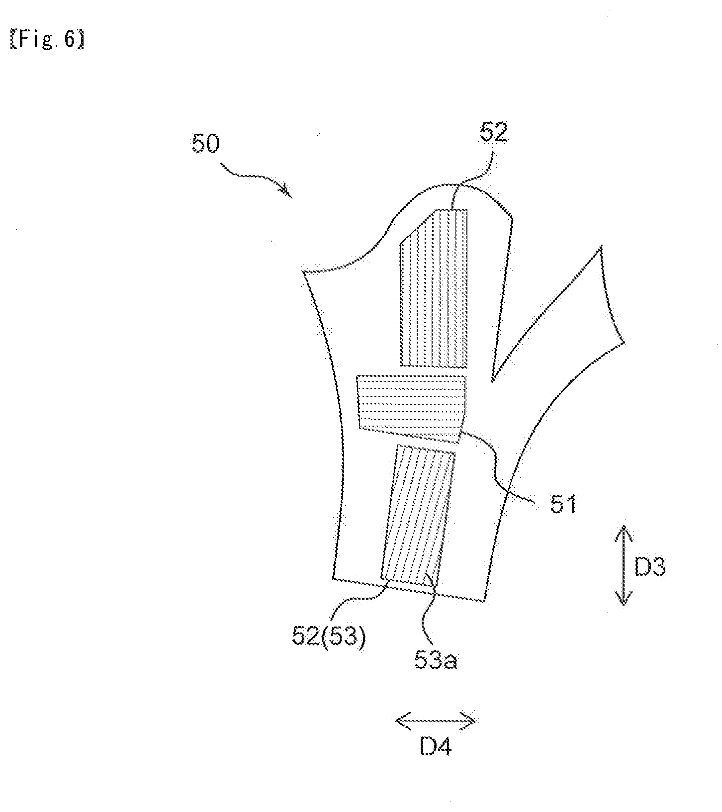
[0083] FIG. 6 shows a plan view of a sleeve fabric 50 constituting the sleeve 4 of the garment 1. As shown in FIG. 6, it is preferred to include a longitudinal perpendicular direction extension part 51 having a larger elongation in a longitudinal direction D3 of the sleeve 4 than an elongation in a direction D4 perpendicular to the longitudinal direction of the sleeve 4, in a part located in an elbow part when worn. By constituting the sleeve 4 of the garment 1 in such a way, the fabric in the elbow part of the sleeve 4 is stretched at the time of motion of bending the elbow, and thus the garment 1 hardly hinders the motion of the wearer.
[0084] It is preferred to include a longitudinal direction extension part 52 having a larger elongation in the direction D4 perpendicular to the longitudinal direction D3 of the sleeve 4 than the elongation in the longitudinal direction of the sleeve 4, on both of the upper and lower sides in the longitudinal direction of the sleeve 4 in the longitudinal perpendicular direction extension part 51. With the garment 1 having the sleeve 4 that is constituted in this way, the sleeve 4 is fitted to the arm of the wearer, and thus can follow the motion of the wearer.
[0085] As the longitudinal perpendicular direction extension part 51, for example, a knit structure of garter knitting or the like can be used. In addition, as the longitudinal direction extension part 52, for example, a knit structure of rib knitting or the like can be used.
[0086] As for the longitudinal perpendicular direction extension part 51 and the longitudinal direction extension part 52, a fabric constituting the longitudinal perpendicular direction extension part 51 and a fabric constituting the longitudinal direction extension part 52 may be joined to the sleeve fabric 50 by welding, sewing, or the like; however, it is preferred that by partially changing the knit structure or weave structure of the sleeve fabric 50, the longitudinal perpendicular direction extension part 51 and the longitudinal direction extension part 52 are included in a fabric constituting the sleeve fabric 50. That is, the sleeve fabric 50, the longitudinal perpendicular direction extension part 51 and the longitudinal direction extension part 52 are preferably integrally constituted. By constituting the sleeve fabric 50 in this way, the unevenness due to the joining can be reduced in each of the boundary parts between the sleeve fabric 50 and the longitudinal perpendicular direction extension part 51, and between the sleeve fabric 50 and the longitudinal direction extension part 52, and therefore, the skin contact of the sleeve 4 can be improved.
[0087] The fabric constituting the sleeve fabric 50 preferably has a larger elongation in the longitudinal direction D3 of the sleeve 4 than the elongation in the direction D4 perpendicular to the longitudinal direction.
[0088] By constituting the sleeve fabric 50 in this way, a sleeve 4 having high followability to the arm during exercise of swinging the arms back and forth, such as jogging can be obtained. As a result, cuffs are hardly turned up during exercise.
[0089] It is preferred that the garment 1 has a sleeve, the sleeve contains a rib knitting part 53, and a longitudinal direction of a furrow 53a of the rib knitting part 53 is not parallel to an axial direction of the sleeve. The expression "axis direction of the sleeve" is referred to as an extending direction of the axis passing through a plane A containing at least a part of a lower end part of a cuff of the sleeve, and a plane B containing an upper end part of the sleeve and being parallel to the plane A. The expression. "longitudinal direction of a furrow 53a of the rib knitting part 53 is not parallel to an axial direction of the sleeve" is referred to as an angle of exceeding 0 degree formed by the longitudinal direction of the furrow 53a of the rib knitting part 53 and the axis direction of the sleeve. By constituting the sleeve in this way, the sleeve becomes easy to follow the motion of putting the arm forward. Therefore, during exercise of swinging the arms back and forth, the garment 1 that is particularly comfortable to the wearer can be obtained.
[0090] The angle formed by the longitudinal direction of the furrow 53a of the rib knitting part 53 and the axis direction of the sleeve is preferably 1 or more degrees, more preferably 3 or more degrees, and furthermore preferably 5 or more degrees. By setting the lower limit value of the angle formed by the longitudinal direction of the furrow 53a of the rib knitting part 53 and the axis direction of the sleeve in this way, the sleeve becomes easy to follow the motion of swinging the arms back and forth, and thus the wear comfort of the garment 1 during exercise can be enhanced. The angle formed by the longitudinal direction of the furrow 53a of the rib knitting part 53 and the axis direction of the sleeve is preferably 45 or less degrees, more preferably 40 or less degrees, and furthermore preferably 35 or less degrees. By setting the upper limit value of the angle formed by the longitudinal direction of the furrow 53a of the rib knitting part 53 and the axis direction of the sleeve in this way, the lower part of the sleeve is easily fitted to the forearm of the wearer.
[0091] Hereinafter, preferred embodiments of the garment according to the embodiment 1 and the embodiment 2 of the present invention will be described.
[0092] The garment 1 is preferably an outer garment or an intermediate garment. The outer garment is a garment to be worn outermost, and the intermediate garment is a garment to be worn intermediately between an outer garment and an inner garment. The garment 1 is an outer garment or an intermediate garment, and it is preferred to wear, for example, underwear or the like that has favorable water absorbency on the inner side of the garment 1.
[0093] The first fabric 10 and the second fabric 20 are preferably joined by welding. Examples of the welding include heat welding, and ultrasonic welding. By joining the first fabric 10 and the second fabric 20 by welding, the joining strength with the first fabric 10 and the second fabric 20 can be enhanced, and the durability of the garment 1 can be enhanced.
[0094] The belt-shaped member 30 is preferably pasted in the joining part 60 in which the first fabric 10 and the second fabric 20 are joined by welding. By welding the first fabric 10 and the second fabric 20, a material constituting the first fabric 10 and a material constituting the second fabric 20 are melted and solidified, and therefore, the joining part 60 becomes hard, and the skin touch becomes poor. By pasting the belt-shaped member 30 to the joining part 60, the joining part 60 having poor skin touch is covered with the belt-shaped member 30, and thus the discomfort feeling is hardly given to the wearer when wearing the garment 1.
EXAMPLES
[0095] Hereinafter, the effects of the present invention will be specifically described by way of example. The following example does not limit the present invention, and all of the design changes according to the gist of the foregoing or following description are included in the technical scope of the present invention.
[0096] By using the first fabric 10 shown in FIG. 3 and the second fabric 20 (20a, 20b) shown in FIG. 4, the first fabric 10 and the second fabric 20 were joined by ultrasonic welding as shown in FIG. 5. The belt-shaped member 30 was arranged and pasted in the joining part 60 between the first fabric 10 and the second fabric 20, and the garment 1 was produced. A base part of each of the first fabric 10 and the second fabric 20 was set to be a rib knit structure, the fabric 41a having higher air-permeability than the air-permeability of at least one of the first fabric 10 and the second fabric 20 was set to be a mesh knit structure, and the fabric 41b having a larger elongation than the elongation of the first fabric 10 in the boundary line perpendicular direction D2 was set to be a thick rib knit structure in which the rib width was larger than the rib width of the base part of each of the first fabric 10 and the second fabric 20. The width of the belt-shaped member 30 was 10 mm. In addition, the thickness of the base part of each of the first fabric 10 and the second fabric 20 was 1.45 mm.
[0097] From the base part of the first fabric 10 in the back panel 3 of the garment 1, a measurement sample of the first fabric 10 was collected along the boundary line parallel direction D1 and the boundary line perpendicular direction D2. From the laminated part 61 being the joining part 60 between the first fabric 10 and the second fabric 20, in which the first fabric 10 and the second fabric 20 were laminated to the belt-shaped member 30, a measurement sample of the laminated part 61 was collected along the boundary line parallel direction D1 and the boundary line perpendicular direction D2 so as to have the laminated part 61 at the center. The size of each measurement sample was 160 to 180 mm in length and 60 mm in width. Note that in the present example, since the knit structures of the base parts of the first fabric 10 and the second fabric 20 are the same, the measurement sample of the first fabric 10 also serves as the measurement sample of the second fabric 20. In a case where the knit structures of the base parts of the first fabric 10 and the second fabric 20 are different, a measurement sample of the second fabric 20 was collected from the base part of the second fabric 20 in the front panel 2.
[0098] A mark was made at the longitudinal center of each measurement sample such that the size of the measurement sample in length was the same as the size of the belt-shaped member 30 in width. In the present example, since the belt-shaped member 30 having a width of 10 mm was used, the marks were made at intervals (hereinafter referred to as the point distance) of 10 mm.
[0099] By using a tensile testing machine, the measurement sample of the first fabric 10 was pulled in the boundary line parallel direction D1, and a displacement L.sub.b1y of the measurement sample of the first fabric 10 in the boundary line parallel direction D1 was measured. Specifically, the measurement sample of the first fabric 10 was fixed to a gripping tool such that the distance between the gripping tools was 100 mm, a load F.sub.b1y was applied to the measurement sample of the first fabric 10 in the boundary line parallel direction D1, and the increased distance of the point distance between the marks made to the measurement sample of the first fabric 10 was measured. The tensile rate of the measurement sample of the first fabric 10 was set to be 200 mm/min. As the measurement device, for example, Table-Top Type Autograph AGS-X 1 kN manufactured by Shimadzu Corporation can be used.
[0100] In a similar manner as in the measurement of the displacement L.sub.b1y of the measurement sample of the first fabric 10 in the boundary line parallel direction D1, a displacement L.sub.b1x of the measurement sample of the first fabric 10 in the boundary line perpendicular direction D2, a displacement L.sub.y of the measurement sample of the laminated part 61 in the boundary line parallel direction D1, and a displacement L.sub.x of the measurement sample of the laminated part 61 in the boundary line perpendicular direction D2 were measured. The measurement results are shown in Table 1.
TABLE-US-00001 TABLE 1 First fabric Laminated part Boundary line parallel Boundary line perpendicular Boundary line parallel Boundary line perpendicular direction D1 direction D2 direction D1 direction D2 Point Test Point Test Point Test Point Test distance Displacement load distance Displacement load distance Displacement load distance Displacement load [mm] [mm] [N] [mm] [mm] [N] [mm] [mm] [N] [mm] [mm] [N] 10 0 0.0 10 0 0.1 10 0 0.0 10 0 0.1 11 1 2.9 11 1 1.3 12 2 7.9 10 0 1.5 12 2 5.8 12 2 2.2 14 4 12.9 10 0 2.7 13 3 9.1 12 2 3.2 16 6 17.4 10 0 3.8 15 5 12.9 13 3 4.1 16 6 21.9 10 0 5.0 16 6 17.3 14 4 5.0 18 8 26.7 10 0 6.2 17 7 22.8 16 6 6.0 19 9 32.4 10 0 7.4 17 7 30.1 16 6 7.0 20 10 39.3 10 0 8.7 18 8 39.8 17 7 8.0 20 10 48.3 11 1 10.0 19 9 53.1 18 8 9.1 21 11 60.3 11 1 11.5 20 10 71.9 20 10 10.3 22 12 76.3 11 1 13.0 20 10 101.7 21 11 11.6 22 12 97.5 11 1 14.8 21 11 144.6 22 12 13.1 24 14 126.1 12 2 16.7 22 12 192.2 23 13 14.6 24 14 165.0 12 2 18.8 22 12 239.8 25 15 16.4 24 14 223.5 12 2 21.2 22 12 287.7 25 15 18.4 26 16 289.5 12 2 24.1
[0101] The loads of F.sub.b1y, F.sub.b1x, F.sub.y, and F.sub.x applied to the measurement sample and the displacements of L.sub.b1y, L.sub.b1x, L.sub.y, and L.sub.x were substituted into the following equations, and the k.sub.tx, k.sub.ty, k.sub.b1x, and k.sub.b1y that are solutions of the following equations were calculated. As described above, in the present example, the knit structures of the base parts of the first fabric 10 and the second fabric 20 were the same. Therefore, it was considered that the values of the k.sub.b1x and k.sub.b1y being solutions of the equations for the first fabric 10 were the same as the values of k.sub.b2x and k.sub.b2y, and the measurement of displacement and the calculation of solution were performed for the measurement sample of the first fabric 10. In a case where the knit structures of the base parts of the first fabric 10 and the second fabric 20 were different, also for the second fabric 20, similarly as in the first fabric 10, the loads of F.sub.b2y and F.sub.b2y, were applied to the measurement sample of the second fabric 20, and the displacements of L.sub.b2y and L.sub.b2x were measured and the solutions of k.sub.b2x and k.sub.b2y were calculated.
F.sub.x=L.sub.x{12k.sub.b1x.times.12k.sub.b2x/(12k.sub.b1x+12k.sub.b2x)+- 6k.sub.tx}
F.sub.y=L.sub.y(3k.sub.b1y+3k.sub.b2y+k.sub.ty)
F.sub.b1x=L.sub.b1x.times.6k.sub.b1x
F.sub.b1y=L.sub.b1y.times.6k.sub.b1y
[0102] FIGS. 7 to 10 are graphs showing the displacement when a load is applied to respective measurement samples. As shown in FIG. 7, the displacement L.sub.b1y was 3.4 mm when a load F.sub.b1y of 10 N was applied to the measurement sample of the first fabric 10 in the boundary line parallel direction D1. As a result, k.sub.b1y=0.49 was obtained from F.sub.b1y=L.sub.b1y.times.6k.sub.b1y.
[0103] As shown in FIG. 8, the displacement L.sub.b1x was 9.1 mm when a load F.sub.b1x of 10 N was applied to the measurement sample of the first fabric 10 in the boundary line perpendicular direction D2. As a result, k.sub.b1x=0.18 was obtained from F.sub.b1x=L.sub.b1x.times.6k.sub.b1x.
[0104] As shown in FIG. 9, the displacement L.sub.y was 2.8 mm when a load F.sub.y of 10 N was applied to the measurement sample of the laminated fabric 61 in the boundary line parallel direction D1. As a result, k.sub.ty=0.63 was obtained from F.sub.y=L.sub.y(3k.sub.b1y+3k.sub.b2y+k.sub.ty).
[0105] As shown in FIG. 10, the displacement L.sub.x was 1.0 mm when a load F.sub.x of 10 N was applied to the measurement sample of the laminated fabric 61 in the boundary line perpendicular direction D2. As a result, k.sub.tx=1.54 was obtained from F=L.sub.x{12k.sub.b1x.times.12k.sub.b2x/(12k.sub.b1x+12k.sub.b2x)+6k.sub.- tx}.
[0106] From the calculated k.sub.tx, k.sub.ty, k.sub.b1x, and k.sub.b1y, a relationship of k.sub.tx>k.sub.ty, and further a relationship of k.sub.b1x<k.sub.b1y are obtained. Therefore, the garment 1 of the present example is excellent in the stretchability in the boundary part between the first fabric 10 and the second fabric 20, and becomes comfortable to the wearer particularly during exercise.
REFERENCE SIGNS LIST
[0107] 1: garment [0108] 2: front panel [0109] 3: back panel [0110] 4: sleeve [0111] 5: hood [0112] 10: first fabric [0113] 20: second fabric [0114] 20a: second fabric on the right side [0115] 20b: second fabric on the left side [0116] 30: belt-shaped member [0117] 41: fabric having larger elongation in the boundary line perpendicular direction [0118] 41a: fabric having higher air-permeability than the air-permeability of at least one of the first fabric and the second fabric [0119] 41b: fabric having larger elongation than the elongation of the first fabric in the boundary line perpendicular direction [0120] 50: sleeve fabric [0121] 51: longitudinal perpendicular direction extension part [0122] 52: longitudinal direction extension part [0123] 53: rib knitting part [0124] 53a: furrow of rib knitting part [0125] 60: joining part [0126] 61: laminated part [0127] 71: armhole [0128] D1: boundary line parallel direction [0129] D2: boundary line perpendicular direction [0130] D3: longitudinal direction of sleeve [0131] D4: direction perpendicular to the longitudinal direction of sleeve
* * * * *
D00000
D00001
D00002
D00003
D00004
D00005
D00006
D00007
D00008
D00009
D00010
XML
uspto.report is an independent third-party trademark research tool that is not affiliated, endorsed, or sponsored by the United States Patent and Trademark Office (USPTO) or any other governmental organization. The information provided by uspto.report is based on publicly available data at the time of writing and is intended for informational purposes only.
While we strive to provide accurate and up-to-date information, we do not guarantee the accuracy, completeness, reliability, or suitability of the information displayed on this site. The use of this site is at your own risk. Any reliance you place on such information is therefore strictly at your own risk.
All official trademark data, including owner information, should be verified by visiting the official USPTO website at www.uspto.gov. This site is not intended to replace professional legal advice and should not be used as a substitute for consulting with a legal professional who is knowledgeable about trademark law.