Personal Cooling Device
CLEMENTE; Roger
U.S. patent application number 16/406262 was filed with the patent office on 2019-11-21 for personal cooling device. The applicant listed for this patent is Roger CLEMENTE. Invention is credited to Roger CLEMENTE.
| Application Number | 20190350279 16/406262 |
| Document ID | / |
| Family ID | 68534554 |
| Filed Date | 2019-11-21 |


| United States Patent Application | 20190350279 |
| Kind Code | A1 |
| CLEMENTE; Roger | November 21, 2019 |
PERSONAL COOLING DEVICE
Abstract
A personal cooling device for providing a cooling air stream is described herein. In one example, the personal cooling device includes an electric fan disposed in a housing, a stay-in-place extended wing member coupled to the housing at a first end, and a fastening mechanism coupled to a second end of the wing member. The fastening mechanism is configured to removably couple the housing to an object, such as a helmet, garment or other object.
| Inventors: | CLEMENTE; Roger; (Hazlet, NJ) | ||||||||||
| Applicant: |
|
||||||||||
|---|---|---|---|---|---|---|---|---|---|---|---|
| Family ID: | 68534554 | ||||||||||
| Appl. No.: | 16/406262 | ||||||||||
| Filed: | May 8, 2019 |
Related U.S. Patent Documents
| Application Number | Filing Date | Patent Number | ||
|---|---|---|---|---|
| 62672885 | May 17, 2018 | |||
| Current U.S. Class: | 1/1 |
| Current CPC Class: | A41D 13/0053 20130101; A41D 13/0025 20130101 |
| International Class: | A41D 13/005 20060101 A41D013/005; A41D 13/002 20060101 A41D013/002 |
Claims
1. A personal cooling device comprising: a housing; an electric fan disposed in the housing; a stay-in-place extended wing member coupled to the housing at a first end; and a fastening mechanism coupled to a second end of the wing member, the fastening mechanism configured to couple the housing to an object.
2. The personal cooling device of claim 1 further comprising: a battery coupled to the fan.
3. The personal cooling device of claim 1, wherein the stay-in-place wing member is flexible and bendable.
4. The personal cooling device of claim 3, wherein the stay-in-place wing member is sufficiently rigid enough to hold a desired position under a weight of the fan.
5. The personal cooling device of claim 1, wherein the fastening mechanism comprises at least one of lever action jaws, hook and loop fasteners, a clip, rivets, screws, bolts, adhesives, magnets and mating projections and slots
6. The personal cooling device of claim 1, wherein the fastening mechanism comprises at least one of lever action jaws, cam locks, a hook and loop fasteners, snaps, magnets, and a male/female geometric feature that mates with a complimentary mating male/female geometric feature.
7. The personal cooling device of claim 1, wherein the fastening mechanism comprises a male/female geometric feature that mates with a complimentary mating male/female geometric feature incorporated into a helmet.
8. The personal cooling device of claim 1 further comprising: a helmet having a lower edge defining an imaginary plane, wherein the wing member is sufficiently bendable to orient an air exhaust port of housing between a direction above the imaginary plane and a direction below the imaginary plane.
9. A personal cooling device configured to removably couple to a lower edge of a helmet, the personal cooling device comprising: a housing; an electric fan disposed in the housing and operable to move air in a direction out an exhaust port of the housing; a fastening mechanism configured to releasably engage the helmet; a stay-in-place extended wing member connecting the housing to the fastening mechanism, the wing member having a length sufficient to position the fan below the lower edge of the helmet.
10. The personal cooling device of claim 9 further comprising: a battery coupled to the fan.
11. The personal cooling device of claim 9, wherein the stay-in-place wing member is flexible and bendable.
12. The personal cooling device of claim 11, wherein the stay-in-place wing member is sufficiently rigid enough to hold a desired position under a weight of the fan.
13. The personal cooling device of claim 9, wherein the fastening mechanism comprises at least one of lever action jaws, hook and loop fasteners, a clip, rivets, screws, bolts, adhesives, magnets and mating projections and slots
14. The personal cooling device of claim 9, wherein the fastening mechanism comprises at least one of lever action jaws, cam locks, a hook and loop fasteners, snaps, magnets, and a male/female geometric feature that mates with a complimentary mating male/female geometric feature of the helmet.
15. The personal cooling device of claim 9, wherein the fastening mechanism comprises a male/female geometric feature that mates with a complimentary mating male/female geometric feature incorporated into a helmet.
16. The personal cooling device of claim 9, wherein the wing member is sufficiently bendable to orient air exiting the exhaust port during operation of the fan between a direction above the imaginary plane and a direction below the imaginary plane.
17. A method of cooling a person, the method comprising: providing power to a cooling device removably coupled to a helmet; and directing air exiting the cooling device below a lower edge of the helmet and into an interstitial space defined between the helmet and a head of a user.
18. The method of claim 17 further comprising: bending a wing member coupling the cooling device to the helmet to direct air exiting the cooling device in a direction away from the lower edge of the helmet and away from the interstitial space defined between the helmet and the head of the user.
19. The method of claim 17 further comprising: connecting the cooling device to the helmet without compromising an integrity of the helmet.
20. The method of claim 17 further comprising: connecting the cooling device to the helmet using at least one of lever action jaws, cam locks, a hook and loop fasteners, snaps, magnets, a clip, rivets, screws, bolts, adhesives, and a male/female geometric feature that mates with a complimentary mating male/female geometric feature of the helmet.
Description
CROSS-REFERENCE TO RELATED APPLICATIONS
[0001] This application claims the benefit of U.S. Provisional Application 62/672,885 filed on May 17, 2018, which is incorporated by reference in its entirety.
BACKGROUND
Field
[0002] Embodiments of the present invention generally relate to a personal cooling device, and more specifically, to a portable battery operated fan that is attachable to objects, such as helmets among other objects.
Description of the Related Art
[0003] There are many types of helmets for head protection. Construction workers, military personnel, welders and bicycle riders are just a few examples. Such helmets when worn in high environmental temperatures may cause heat stress, fatigue and vision problems. To help prevent this, personal cooling devices, such as fans, of different sizes and shapes have been utilized to provide an evaporated air flow stream between the head and the inside of the helmet. Such personal cooling devices may require the fan to be installed in a manner that requires holes in the helmet, or require fan intake holes disposed through the helmet. However, holes through the helmet undesirably compromise the structural integrity and safety features of the helmet.
[0004] Thus, there is a need for an improved personal cooling device.
SUMMARY
[0005] A personal cooling device for providing a cooling air stream is described herein. In one example, the personal cooling device includes an electric fan disposed in a housing, a stay-in-place extended wing member coupled to the housing at a first end, and a fastening mechanism coupled to a second end of the wing member. The fastening mechanism is any attachment device may be configured to be temporary or permanent that allows the personal cooling device to be coupled to an object, such as a helmet, garment or other object.
[0006] In another example, a personal cooling device is provided that is configured to removably couple to a lower edge of a helmet. The personal cooling device includes an electric fan disposed in a housing, a fastening mechanism configured to releasably engage the helmet, and a stay-in-place extended wing member connecting the housing to the fastening mechanism. The electric fan is operable to move air in a direction out an exhaust port of the housing. The wing member has a length sufficient to position the fan below the lower edge of the helmet.
[0007] In yet another example, a method of cooling a person is provided that includes providing power to a cooling device removably coupled to a helmet, and directing air exiting the cooling device below a lower edge of the helmet and into an interstitial space defined between the helmet and a head of a user.
BRIEF DESCRIPTION OF THE DRAWINGS
[0008] So that the manner in which the above recited features of the present disclosure can be understood in detail, a more particular description of the disclosure, briefly summarized above, may be had by reference to embodiments, some of which are illustrated in the appended drawings. It is to be noted, however, that the appended drawings illustrate only exemplary embodiments and are therefore not to be considered limiting of its scope, may admit to other equally effective embodiments.
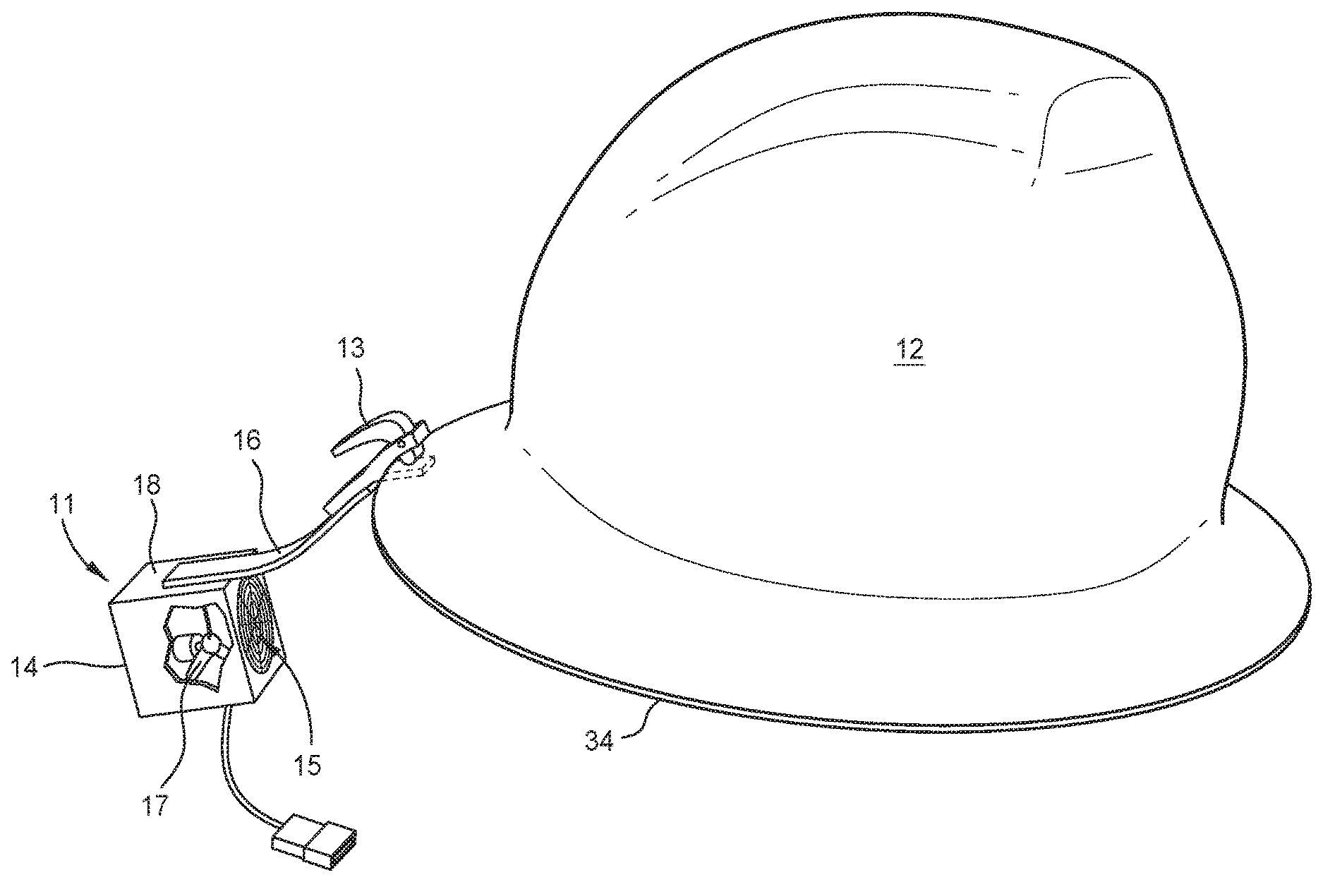
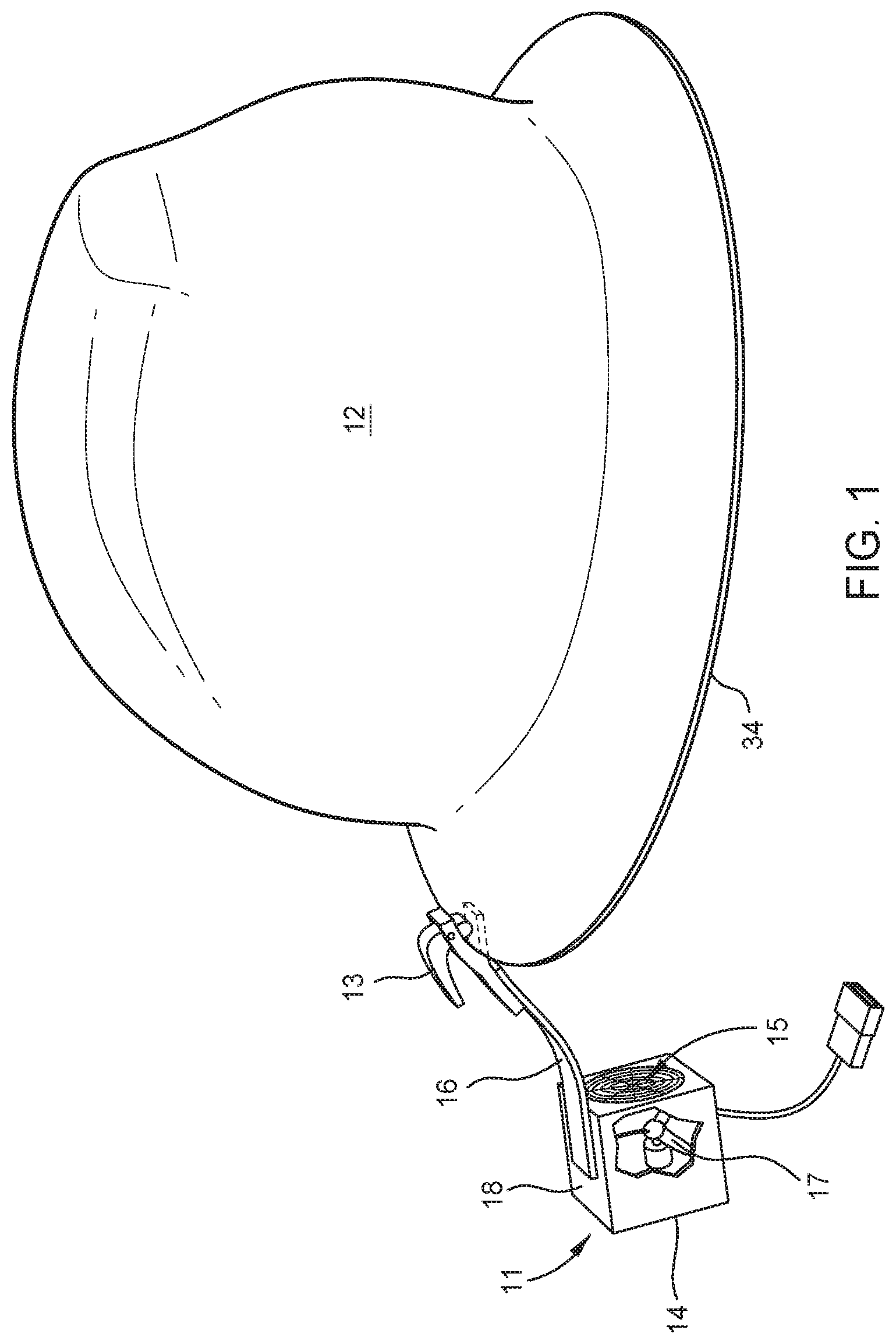
[0009] FIG. 1 is a schematic depiction of a personal cooling device according to one or more embodiments.
[0010] FIG. 2 is a front view of the personal cooling device of FIG. 1.
[0011] FIG. 3 is a side view of the personal cooling device attached to a helmet.
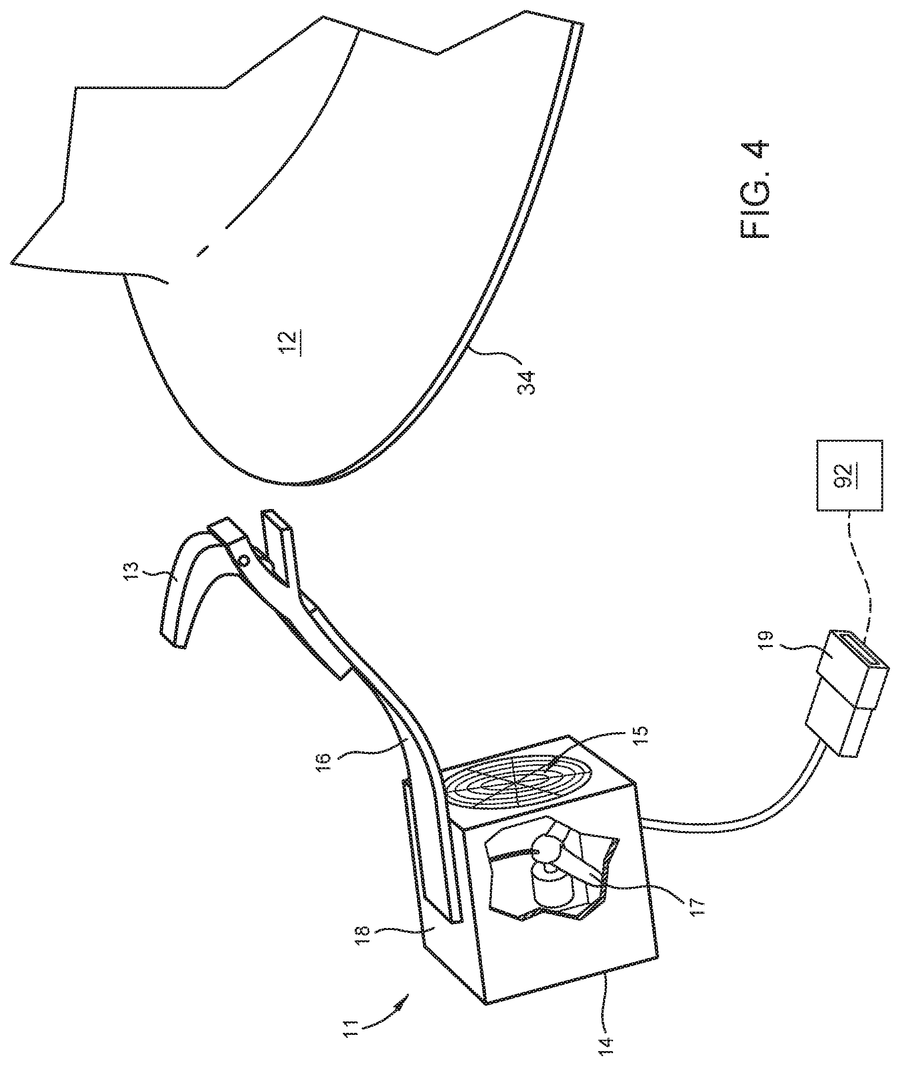
[0012] FIG. 4 is a side view of the personal cooling device unattached to a helmet.
[0013] FIGS. 5A-5B are side views of the personal cooling device moving air flow in different orientations.
[0014] To facilitate understanding, identical reference numerals have been used, where possible, to designate identical elements that are common to the figures. It is contemplated that elements and features of one embodiment may be beneficially incorporated in other embodiments without further recitation.
DETAILED DESCRIPTION
[0015] As discussed above, there are many types of helmets for head protection. Construction workers, military personnel, welders and bicycle riders are just a few examples. Such helmets when worn in high environmental temperatures may cause heat stress, fatigue and vision problems. To help prevent this, personal cooling devices such as fans have been utilized to provide an evaporated air flow stream between the head and the inside of the helmet. Undesirably, such personal cooling devices are installed in a manner that requires holes in the helmet, or require fan intake holes disposed through the helmet, which compromise the structural integrity and safety features of the helmet.
[0016] Disclosed herein is a personal cooling device that advantageously provides for an improved head and neck cooling device that may be affixed to headgear, such as a helmet, without compromising the integrity of the headgear. The personal cooling device uses a fastening mechanism that both allows the angular adjustment of the output of the fan, while allowing easy adjustment and secure attachment to many types of helmets or other types of head protection gear without the need for holes formed through the helmet. In one example, the fastening mechanism utilizes lever action jaws, cam locks, a hook and loop fasteners, or various temporary or permanent means including but not limited to adhesives, magnets or mating projections and slots, among others, to secure the fan to the helmet. Since the personal cooling device does not utilize holes formed through the helmet, the personal cooling device will not compromise the structural integrity or safety features of the helmet, require an air discharge distribution channel, intake helmet holes or internal placement of the fan within the helmet.
[0017] In some examples, the personal cooling device of the present invention includes a portable battery operated fan that is encased in a housing. The housing includes a flexible stay-in-place wing member extending from the housing and coupled to the fastening mechanism. The housing may be flexible, bendable or rigid. The flexible stay-in-place wing member is adjustable, flexible, and bendable in a manner that substantially able to retain the fan in an orientation relative to the fastening mechanism and the helmet as to direct a cooling air stream generated by the fan to a desired locations, such as under the helmet or inside the collar of a shirt or jacket. The rechargeable battery is located remote from the housing and is coupled to the fan by wire leads. The opposite end of the flexible stay-in-place wing member is used to attach the fan housing firmly to the helmet by the fastening mechanism that does not change the structural integrity or safety features of the helmet or other types of head protection gear. The stay-in-place wing member, when adjusted to a desired shape, will hold its desired shape allowing the fan to be oriented in different directions when attached to the helmet, head protection gear, clothing or other objects or surfaces by the fastening means. Thus, as utilized herein, the modifier "stay-in-place" as applied to the wing member means the wing member, although flexible and bendable, the wing member sufficiently rigid to support the weight of the fan in an given orientation relative to the fastening mechanism substantially without allowing the position of the fan to sag under its own weight when suspended cantilevered from the fastening mechanism (when attached to an object). This allows the personal cooling device with the flexible-bendable stay-in-place wing member to position the housing such that the fan is held in a desired orientation relative to the helmet during the operation of the fan.
[0018] In other examples where safety and integrity of the helmet or head gear is not as important or will not be compromised due to the helmet or head gear design, the fastening mechanism can be attached to the helmet by screws, rivets, bolts or other fasteners or with other fastening techniques. In yet other examples, the fastening mechanism can be permanently attached to the helmet or head gear during a helmet/head gear manufacturing process, such as by molding, fusion, welding or other suitable technique.
[0019] In operation once adjusted to a desired position, the battery operated fan encased in a flexible-bendable or rigid housing member intakes and exhausts an air flow stream in a desired direction. During operation, the wing member of the personal cooling device is securely attached and adjusted to the desired position on the helmet so as to orientate the exhaust port, and the battery operated fan is energized, thereby creating an exhaust air flow stream towards the head, neck or other areas of the body. As the air passes over the body it creates a cooling affect by evaporating body moisture. In one example, the personal cooling device having one end of the flexible-bendable stay-in-place extended wing member attached securely to the helmet by closing the snap locking clip or other holding mechanism of the fastening mechanism, while the other end of the flexible-bendable stay-in-place extended wing member is coupled to the housing such that the fan is positioned below the lower edge of the helmet and in an orientation that directs air flow between the users head and the lower edge of the helmet to create the cooling affect.
[0020] The personal cooling device described above can be also used to cool other parts of the body since the adjustable flexible bendable wing member can be easily attached to other objects such as shirts, vest, jackets etc.
[0021] The personal cooling device may be utilized to cool various parts of the body, such as but limited to the head and neck. The personal cooling device uses a portable battery operated fan encased in a flexible, bendable or rigid housing that has an adjustable, flexible-bendable wing member that can easily be attached to helmets, headgear or other objects such as shirts, vest, jackets, apparel and the like, among other objects.
[0022] The personal cooling device has a battery operated fan that uses the exhaust air flow stream to cool the body. The personal cooling device includes a bendable, adjustable or rigid housing that has an adjustable, flexible-bendable wing member that can be attached to a helmet or other objects without compromising their structural integrity or safety features. Using a holding mechanism such as an open-closed snap clip attached to the bendable flexible wing member, the personal cooling device can be removed or reattached temporarily from a surface or permanently attached by first coating the open snap clip surfaces with a temporary adhesive, such as LOCTITE.RTM. or similar compound, then closing the snap clip on the desired surface.
[0023] FIG. 1 is a side view of the personal cooling device 11. The personal cooling device 11 includes an electric fan 17 disposed in a housing 18. The housing 18 includes an intake port 14 and exhaust port 15 to allow air to be moved by the fan 17 through the housing 18. The orientation of the housing 18, and thus the exhaust port 15, sets the direction of the air flow leaving the housing 18 so that the stream of cooling air may be directed to a desired location, such as a head or other body part of a user. The housing 18 is attachable to an object via a gripper 13, such as a fastening mechanism, via a flexible, bendable wing member 16 that extends from the housing 18. The wing member 16 may be a metal tab, coated metal, or other suitable material. In one example, the gripper 13, hereinafter referred to as fastening mechanism 13, is utilized to removably secure the personal cooling device 11 to a helmet 12. In one example, the fastening mechanism 13 is configured to engage and removably secure the personal cooling device 11 to a lower edge 34 of the helmet 12.
[0024] The wing member 16 has two ends, one end attached to the housing 18 of the fan 17 and the other end attached to an object, such as for example a helmet, via the fastening mechanism 13. The end of the wing member 16 may be attached to the housing 18 of the fan 17 in a temporary or permanent manner. For example, the wing member 16 may be attached to the housing 18 using adhesives, rivets, screws, heat shrink tubing, wrap, hook and loop fastener, or by other suitable technique. In another example, the end of the wing member 16 can be attached to an object, such as the helmet, temporally by using the fastening mechanism 13 or permanently in a process that allows the wing member 16 to be attached to an object during manufacture such as integrally molded as part of the helmet. As describe above, the wing member 16 is then attached to the housing 18 utilizing temporary or permanent fasteners/fastening techniques. In the example depicted in FIG. 1, the wing member 16 is permanently coupled to the housing 18 (for example by fasteners), and removably coupled to the object (via the fastening mechanism 13).
[0025] FIG. 2 shows the fan 17 installed in a flexible, bendable or rigid housing 18 attached to helmet 12 by the fastening mechanism 13 in the closed position. Wire leads 19 connect to a power source 92 or a portable rechargeable battery (not shown) that may be attached to a garment worn by the user. The fastening mechanism 13 may be lever action jaws, cam locks, a hook and loop fasteners, or various temporary or permanent means including but not limited to clips, rivets, screws, bolts, adhesives, magnets or mating projections and slots, among others.
[0026] In the example of FIG. 2, the fastening mechanism 13 is structurally functional to allow the personal cooling device 11 to be removably attached and detached to a helmet 12. For example, the personal cooling device 11 may be lever action jaws, cam locks, a hook and loop fasteners, snaps, magnets or has a male/female geometric feature that slidingly or otherwise mates with a complimentary mating male/female geometric feature incorporated into helmet 12 or other garment or object.
[0027] FIG. 3 shows the fastening mechanism 13 attached to helmet 12 such that the housing 18, and thus the exhaust port 15, is held in a position below the lower edge 34 of the helmet 12 to allow air exiting the exhaust port 15 can be directed between the helmet 12 and the head of a user. The adjustable flexible bendable wing member 16 can move so that the personal cooling device 11 can change positions so that exhaust port 15 can discharge an air flow stream in a desired direction towards a person's head, neck, both or other location.
[0028] FIG. 4 shows the removable cooling device 11 with the fastening mechanism 13 in the open position that is attached to adjustable, flexible-bendable wing member 6. The fastening mechanism 13 illustrated in FIG. 4 includes a fork having a locking lever that is actuatable to pinch, and thus releasably secure, an object, such as the lower edge 34 of the helmet 12, within the fork. In one example, the locking lever rotates a cam to move the lobe of the cam into the area between the forks. In another example, the locking lever squeezes the forks together. It is contemplated that a wide variety of fastening mechanisms 13 may be utilized to perform the function of releasably securing the cooling device 11 to the helmet 12.
[0029] In operation, the fan 17 in FIG. 2 is connected by wire leads 19 to the power source 92, such as a portable rechargeable battery (shown in phantom), that may be remotely disposed on the user. Once energized, exhaust port 15 discharges an air flow stream. By adjusting the flexible-bendable wing member 16, as shown in FIGS. 5A-5B, the exhaust air flow stream exiting the exhaust port 15 can be adjusted towards the area between the head 32 and the inside of the helmet 12 (as depicted by dashed arrows 98 in FIG. 5A) or towards the neck 31 (as shown by dashed arrows 96 in FIG. 5B). As illustrated in FIGS. 5A-5B, the flexible-bendable wing member 16 allows the positional orientation of the exhaust port 15 to be changed relative to the fastening member 13 and the helmet 12. As the air flow passes over the body, the moving air creates a cooling affect by evaporating body moisture from the surface of the body. Since the wing member 16 is bendable (using the lower edge 34 of the helmet 12 to define a horizontal plane), the wing member 16 may orient the exhaust port 15 of the housing 18 between a direction above the horizontal plane as illustrated by direction of the dashed arrows 98 indicative of the air flow exiting the housing 18 and a direction below the horizontal plane as illustrated by direction of the dashed arrows 96 indicative of the air flow exiting the housing 18. As the air flow passes over the body, the moving air creates a cooling affect by evaporating body moisture from the surface of the body.
[0030] In one example, the operation of the cooling device may be described as a method of cooling a person. The method includes providing power to a cooling device removably coupled to a helmet, and directing air exiting the cooling device below a lower edge of the helmet and into an interstitial space defined between the helmet and a head of a user.
[0031] In one example, the method may further include bending a wing member coupling the cooling device to the helmet to direct air exiting the cooling device in a direction away from the lower edge of the helmet and away from the interstitial space defined between the helmet and the head of the user.
[0032] In another example, any of the methods described above may also include connecting the cooling device to the helmet without compromising the integrity of the helmet.
[0033] In another example, any of the methods described above may also include connecting the cooling device to the helmet using at least one of lever action jaws, cam locks, a hook and loop fasteners, snaps, magnets, a clip, rivets, screws, bolts, adhesives, and a male/female geometric feature that mates with a complimentary mating male/female geometric feature of the helmet.
[0034] Thus, a personal cooling device has been described above that advantageously provides improved head and/or neck cooling. Advantageously, the cooling device may be affixed to headgear, such as a helmet, without compromising the integrity of the headgear. Since the personal cooling device does not utilize holes formed through the headgear, the personal cooling device will not compromise the structural integrity or safety features of the headgear, require an air discharge distribution channel, intake headgear holes or internal placement of the fan within the headgear.
* * * * *
D00000
D00001
D00002
D00003
D00004
D00005
D00006
XML
uspto.report is an independent third-party trademark research tool that is not affiliated, endorsed, or sponsored by the United States Patent and Trademark Office (USPTO) or any other governmental organization. The information provided by uspto.report is based on publicly available data at the time of writing and is intended for informational purposes only.
While we strive to provide accurate and up-to-date information, we do not guarantee the accuracy, completeness, reliability, or suitability of the information displayed on this site. The use of this site is at your own risk. Any reliance you place on such information is therefore strictly at your own risk.
All official trademark data, including owner information, should be verified by visiting the official USPTO website at www.uspto.gov. This site is not intended to replace professional legal advice and should not be used as a substitute for consulting with a legal professional who is knowledgeable about trademark law.