Header Panel Assembly For Preventing Air Circulation Above Electronic Equipment Enclosure
KRIETZMAN; William Drew
U.S. patent application number 16/422295 was filed with the patent office on 2019-11-14 for header panel assembly for preventing air circulation above electronic equipment enclosure. The applicant listed for this patent is CHATSWORTH PRODUCTS, INC.. Invention is credited to William Drew KRIETZMAN.
| Application Number | 20190350110 16/422295 |
| Document ID | / |
| Family ID | 46018959 |
| Filed Date | 2019-11-14 |


View All Diagrams
| United States Patent Application | 20190350110 |
| Kind Code | A1 |
| KRIETZMAN; William Drew | November 14, 2019 |
HEADER PANEL ASSEMBLY FOR PREVENTING AIR CIRCULATION ABOVE ELECTRONIC EQUIPMENT ENCLOSURE
Abstract
A hot/cold aisle containment system includes a frame structure, at least one electronic equipment enclosure installed at least partially within the frame structure, and a header panel assembly. The frame structure is adapted to be at least partially covered by one or more panels to define an interior space and includes a vertical member and a horizontal member. The header panel assembly is installed between a top of the at least one electronic equipment enclosure and the horizontal member of the frame structure to prevent circulation of air above the enclosure. The header panel assembly includes a main panel and at least one seal.
| Inventors: | KRIETZMAN; William Drew; (Castle Rock, CO) | ||||||||||
| Applicant: |
|
||||||||||
|---|---|---|---|---|---|---|---|---|---|---|---|
| Family ID: | 46018959 | ||||||||||
| Appl. No.: | 16/422295 | ||||||||||
| Filed: | May 24, 2019 |
Related U.S. Patent Documents
| Application Number | Filing Date | Patent Number | ||
|---|---|---|---|---|
| 15051087 | Feb 23, 2016 | 10306812 | ||
| 16422295 | ||||
| 13291861 | Nov 8, 2011 | 9313927 | ||
| 15051087 | ||||
| 61411359 | Nov 8, 2010 | |||
| 61411373 | Nov 8, 2010 | |||
| Current U.S. Class: | 1/1 |
| Current CPC Class: | H05K 7/20745 20130101; H05K 7/20836 20130101 |
| International Class: | H05K 7/20 20060101 H05K007/20 |
Claims
1: A hot/cold aisle containment system, comprising: a frame structure adapted to be at least partially covered by one or more panels to define an interior space, the frame structure including a first vertical member, a second vertical member, and a rigid, continuous, horizontal member, wherein the horizontal member is supported directly by the first and second vertical members; at least one electronic equipment enclosure installed at least partially within the frame structure such that the first and second vertical members are on opposite sides of the at least one electronic equipment enclosure and the horizontal member of the frame structure extends from one side of the at least one electronic equipment enclosure to the other; and a header panel assembly installed between, and supported by, a top of the at least one electronic equipment enclosure and the horizontal member of the frame structure to prevent circulation of air above the enclosure, the header panel assembly including a main panel and at least one seal.
2: The hot/cold aisle containment system of claim 1, wherein the at least one seal is disposed along the lower edge of the main panel and adapted to be held in place between the bottom of the main panel and a top surface of the at least one electronic equipment enclosure.
3: The hot/cold aisle containment system of claim 1, wherein the at least one seal is disposed along a side edge of the main panel and adapted to be held in place between the side of the main panel and an adjacent structure.
4: The hot/cold aisle containment system of claim 1, wherein the header panel assembly further includes a fixed bracket adapted to be supported by the horizontal member of the frame structure, and wherein the main panel is adapted to be adjustably coupled to the fixed bracket.
5: The hot/cold aisle containment system of claim 4, wherein the header panel assembly further includes at least one clamp for retaining a portion of the main panel against a portion of the fixed bracket.
6: The hot/cold aisle containment system of claim 1, wherein a V-shaped flange is disposed at an edge of the main panel, and wherein the at least one seal is disposed at least partially in a groove defined by the V-shaped flange.
7: The hot/cold aisle containment system of claim 1, wherein a generally perpendicular flange is disposed at an edge of the main panel, and wherein the at least one seal is disposed along an outer edge of the generally perpendicular flange.
8: The hot/cold aisle containment system of claim 1, wherein an angled flange is disposed at an edge of the main panel, and wherein the at least one seal is disposed along an outer edge of the angled flange.
9: The hot/cold aisle containment system of claim 1, wherein the at least one seal is compressible.
10: The hot/cold aisle containment system of claim 1, wherein the at least one seal is a brush seal.
11: The hot/cold aisle containment system of claim 1, wherein the at least one seal is a deflectable blade seal.
12: The hot/cold aisle containment system of claim 1, wherein the main panel is mounted to the horizontal member and adapted to be adjustable in a vertical direction relative to the horizontal member.
13-22: (canceled)
23: The hot/cold aisle containment system of claim 1, wherein the header panel assembly further includes a fixed bracket adapted to be supported by the horizontal member of the frame structure, and wherein the main panel is adapted to be adjustably coupled to the fixed bracket.
Description
CROSS-REFERENCE TO RELATED APPLICATION
[0001] The present application is a U.S. continuation patent application of, and claims priority under 35 U.S.C. .sctn. 120 to, U.S. nonprovisional patent application Ser. No. 15/051,087, filed Feb. 23, 2016 and entitled "HEADER PANEL ASSEMBLY FOR PREVENTING AIR CIRCULATION ABOVE ELECTRONIC EQUIPMENT ENCLOSURE," which '087 application published as U.S. Patent Application Publication No. US 2016/0249488 A1 on Aug. 25, 2016 and issued as U.S. Pat. No. 10,306,812 on May 28, 2019, which '087 application, the application publication thereof, and the patent issuing therefrom are each incorporated by reference herein in their respective entireties, and which '087 application is a U.S. continuation patent application of, and claims priority under 35 U.S.C. .sctn. 120 to, U.S. nonprovisional patent application Ser. No. 13/291,861, filed Nov. 8, 2011 and entitled "HEADER PANEL ASSEMBLY FOR PREVENTING AIR CIRCULATION ABOVE ELECTRONIC EQUIPMENT ENCLOSURE," which '861 application published as U.S. Patent Application Publication No. US 2012/0112612 A1 on May 10, 2012 and issued as U.S. Pat. No. 9,313,927 on Apr. 12, 2016, which '861 application, the application publication thereof, and the patent issuing therefrom are each incorporated by reference herein in their respective entireties, and which '861 application is a U.S. nonprovisional patent application of, and claims priority under 35 U.S.C. .sctn. 119(e) to, U.S. provisional patent application Ser. No. 61/411,359, filed Nov. 8, 2010 and entitled "ADJUSTABLE WALL ASSEMBLY FOR HOT/COLD AISLE CONTAINMENT SYSTEM," which '359 application is incorporated by reference herein in its entirety, and which '861 application is a U.S. nonprovisional patent application of, and claims priority under 35 U.S.C. .sctn. 119(e) to, U.S. provisional patent application Ser. No. 61/411,373, filed Nov. 8, 2010 and entitled "HEADER PANEL ASSEMBLY FOR PREVENTING AIR CIRCULATION ABOVE ELECTRONIC EQUIPMENT ENCLOSURE," which '373 application is incorporated by reference herein in its entirety.
COPYRIGHT STATEMENT
[0002] All of the material in this patent document is subject to copyright protection under the copyright laws of the United States and other countries. The copyright owner has no objection to the facsimile reproduction by anyone of the patent document or the patent disclosure, as it appears in official governmental records but, otherwise, all other copyright rights whatsoever are reserved.
BACKGROUND OF THE PRESENT INVENTION
Field of the Present Invention
[0003] The present invention relates generally to structures and methods of thermal management in a data center, and, in particular, to a header panel assembly for installation above electronic equipment enclosures in a hot aisle containment structure.
Background
[0004] Rack-mounted computer and data storage equipment generates heat during normal operation. When equipment is enclosed in racks, cabinets and other electronic equipment enclosures (hereinafter, collectively, referred to as "enclosures"), heat generated by the equipment can concentrate within the enclosure and cause equipment to overheat and shut down. Thus, proper thermal management is a fundamental aspect of the installation and use of such equipment. Moreover, thermal management is particularly important in data centers in which multiple enclosures are installed, each with heat-generating equipment mounted therein.
[0005] Many techniques and solutions have been proposed and used with regard to thermal management in such data centers. One such solution involves utilization of a containment structure to receive heated exhaust air from enclosures installed in the data center or computer room. Enclosures are typically arranged in a row facing with their sides abutting one another. Cool air is drawn into the enclosures from outside the containment structure to cool the equipment mounted in each enclosure. Heated exhaust air is then expelled from the enclosures into a common area within the containment structure, which is segregated from the supply of cool air. Heated exhaust air may then be routed from the containment structure and cooled before being re-circulated into the supply of cool air.
[0006] A common difficulty encountered in many known containment structures involves co-mingling of the heated exhaust air with the supply of cool air, which negatively impacts efficiency in the system. Co-mingling may occur for a variety of reasons, but often arises in connection with openings or gaps surrounding enclosures that are installed in the structure. If a gap exists after an enclosure is installed in the structure, heated exhaust air has the potential to travel through the gap and back into the supply of cool air, thereby reducing cooling efficiency in the system. For example, the gaps that have long existed between the tops of enclosures and the ceiling or other structure above the enclosures permit recirculation of heated air that has been exhausted from the rear of an enclosure over the enclosure where it mingles with the cooling air being supplied to the front of the enclosure for intake therein.
[0007] Additionally, openings or gaps in the containment structure may have the effect of causing equipment located near the gap to run at a higher operating temperature as warmer air that escapes from within the containment structure is drawn back in to cool the equipment. As a result, over time, such equipment may have a decreased operating life relative to other equipment installed therein.
[0008] Further issues may arise if enclosures with varying dimensions are installed within the same containment structure. For example, if enclosures with different vertical dimensions happen to be installed adjacent to one another within the same containment structure, differently-sized panels or blanks must be used to seal off any gaps that are formed above the enclosures. If such panels do not provide a good fit to seal the gap, then inefficiency is likely to exist as heated exhaust air escapes from the containment structure and mixes with the supply of cool air.
[0009] Accordingly, a need exists for a containment system that avoids the shortcomings of known containment structure solutions. This, and other needs, are addressed by one or more aspects of the present invention.
SUMMARY OF THE PRESENT INVENTION
[0010] Broadly defined, the present invention according to a first aspect includes a hot/cold aisle containment system substantially as shown and described.
[0011] Broadly defined, the present invention according to a second aspect includes a hot/cold aisle containment system having a header panel assembly installed between a horizontal member thereof and an electronic equipment enclosure, substantially as shown and described.
[0012] Broadly defined, the present invention according to a third aspect includes a hot/cold aisle containment system. The containment system includes a frame structure, at least one electronic equipment enclosure installed at an end of the frame structure, and a header panel assembly. The frame structure is adapted to be at least partially covered by one or more panels to define an interior space and includes a vertical member and a horizontal member. The header panel assembly is installed between a top of the at least one electronic equipment enclosure and the horizontal member of the frame structure to prevent circulation of air above the enclosure.
[0013] In features of this aspect, the header panel assembly may include a main panel and at least one seal, the at least one seal being disposed along the lower edge of the main panel and adapted to be held in place between the bottom of the main panel and a top surface of the at least one electronic equipment enclosure; the at least one seal may be compressible; the header panel assembly may further include a fixed bracket adapted to be supported by the horizontal member of the frame structure, wherein the main panel is adapted to be adjustably coupled to the fixed bracket; the header panel assembly may further include at least one clamp for retaining a portion of the main panel against a portion of the fixed bracket; a V-shaped flange may be disposed at the lower edge of the main panel, wherein the at least one seal is disposed at least partially in a groove defined by the V-shaped flange; and a V-shaped flange may be disposed at a side edge of the main panel, wherein the at least one seal is disposed at least partially in a groove defined by the V-shaped flange.
[0014] In further features of this aspect, the hot/cold aisle containment system may further include a side seal assembly installed between a side of the at least one electronic equipment enclosure and the vertical member of the frame structure to prevent circulation of air around the enclosure; the side seal assembly may include a vertical support bracket and at least one seal, the vertical support bracket being adapted to support the side seal assembly from the vertical member of the frame structure; the vertical support bracket may include one or more horizontal slots to facilitate lateral adjustment thereof; a V-shaped flange may be disposed along an edge of the vertical support bracket, wherein the at least one seal is disposed at least partially in a groove defined by the V-shaped flange; and the side seal assembly may be adapted to extend from the top to the bottom of the frame structure.
[0015] Broadly defined, the present invention according to a fourth aspect includes a hot/cold aisle containment system. The containment system includes a frame structure, at least one electronic equipment enclosure installed at an end of the frame structure, and a side seal assembly. The frame structure is adapted to be at least partially covered by one or more panels to define an interior space and includes a vertical member. The side seal assembly is installed between a side of the at least one electronic equipment enclosure and the vertical member of the frame structure to prevent circulation of air around the enclosure.
[0016] In features of this aspect, the side seal assembly may include a vertical support bracket and at least one seal, the vertical support bracket being adapted to support the side seal assembly from the vertical member of the frame structure; the vertical support bracket may include one or more horizontal slots to facilitate lateral adjustment thereof; and a V-shaped flange may be disposed along an edge of the vertical support bracket, wherein the at least one seal is disposed at least partially in a groove defined by the V-shaped flange.
[0017] Broadly defined, the present invention according to a fifth aspect includes a hot/cold aisle containment system. The containment system includes a frame structure, a header panel assembly, a side seal assembly, and at least one electronic equipment enclosure. The frame structure is adapted to be at least partially covered by one or more panels to define an interior space and includes a vertical member and a horizontal member. The header panel assembly depends from the horizontal member of the frame structure, and the side seal assembly depends from the vertical member of the frame structure. The at least one electronic equipment enclosure is installed at least partially within the frame structure such that a top of the enclosure is sealed by the header panel assembly and a side of the enclosure is sealed by the side seal assembly.
[0018] In features of this aspect, the header panel assembly may include a main panel and at least one seal, the at least one seal being disposed along the lower edge of the main panel and adapted to be held in place between the bottom of the main panel and a top surface of the at least one electronic equipment enclosure; the at least one seal may be compressible; the header panel assembly may further include a fixed bracket adapted to be supported by the horizontal member of the frame structure, wherein the main panel is adapted to be adjustably coupled to the fixed bracket; the header panel assembly may further include at least one clamp for retaining a portion of the main panel against a portion of the fixed bracket; a V-shaped flange may be disposed at the lower edge of the main panel, wherein the at least one seal is disposed at least partially in a groove defined by the V-shaped flange; and a V-shaped flange may be disposed at a side edge of the main panel, wherein the at least one seal is disposed at least partially in a groove defined by the V-shaped flange.
[0019] In further features of this aspect, the side seal assembly may include a vertical support bracket and at least one seal, the vertical support bracket being adapted to support the side seal assembly from the vertical member of the frame structure; the vertical support bracket may include one or more horizontal slots to facilitate lateral adjustment thereof; a V-shaped flange may be disposed along an edge of the vertical support bracket, wherein the at least one seal is disposed at least partially in a groove defined by the V-shaped flange; and the side seal assembly may be adapted to extend from the top to the bottom of the frame structure.
[0020] Broadly defined, the present invention according to a sixth aspect includes a header panel assembly, for use in connection with a hot/cold aisle containment system, substantially as shown and described.
[0021] Broadly defined, the present invention according to a seventh aspect includes a header panel assembly. The header panel assembly includes a fixed bracket, adapted to be supported by a horizontal frame structure of a hot/cold aisle containment system; a main panel, having a lower edge, that is adjustably coupled to the fixed bracket; and a seal, disposed along the lower edge of the main panel, that is adapted to be held in place between the bottom of the main panel and a top surface of at least one electronic equipment enclosure installed beneath the header panel assembly.
[0022] In features of this aspect, the seal may be compressible; the header panel assembly may further include at least one clamp for retaining a portion of the main panel against a portion of the fixed bracket; a V-shaped flange may be disposed at the lower edge of the main panel, wherein the seal is disposed at least partially in a groove defined by the V-shaped flange; and the main panel may further include a side edge having an additional V-shaped flange, wherein an additional seal is disposed along the side edge at least partially in a groove defined by the additional V-shaped flange and is adapted to be held in place between the side of the main panel and an adjacent structure.
[0023] Broadly defined, the present invention according to an eighth aspect includes a header panel assembly. The header panel assembly includes a fixed bracket, adapted to be supported by a horizontal frame structure of a hot/cold aisle containment system; a main panel, having a side edge, that is adjustably coupled to the fixed bracket; and a seal, disposed along the side edge of the main panel, that is adapted to be held in place between the side of the main panel and an adjacent structure.
[0024] In features of this aspect, the seal may be compressible; a V-shaped flange may be disposed at the side edge of the main panel, wherein the seal is disposed at least partially in a groove defined by the V-shaped flange; and the adjacent structure may be a side seal assembly.
[0025] Broadly defined, the present invention according to a ninth aspect includes a side seal assembly, for use in connection with a hot/cold aisle containment system, substantially as shown and described.
[0026] Broadly defined, the present invention according to a tenth aspect includes a side seal assembly. The side seal assembly includes a vertical support bracket, adapted to be supported by a vertical frame structure of a hot/cold aisle containment system, that includes a V-shaped flange extending vertically along the side thereof; and a seal, disposed within a groove defined by the V-shaped flange, that is adapted to be held in place between the side of the vertical support bracket and an adjacent electronic equipment enclosure.
[0027] In features of this aspect, the seal may be compressible; and the vertical support bracket may include one or more horizontal slots to facilitate lateral adjustment thereof.
[0028] Broadly defined, the present invention according to an eleventh aspect includes a method of sealing a hot/cold aisle containment system as substantially shown and described.
[0029] Broadly defined, the present invention according to a twelfth aspect includes a hot/cold aisle containment system that includes a frame structure and at least one electronic equipment enclosure installed at least partially within the frame structure, and a header panel assembly. The frame structure is adapted to be at least partially covered by one or more panels to define an interior space. The frame structure includes a vertical member and a horizontal member. The header panel assembly is installed between a top of the at least one electronic equipment enclosure and the horizontal member of the frame structure to prevent circulation of air above the enclosure. The header panel assembly includes a main panel and at least one seal.
[0030] In features of this aspect, the at least one seal may be disposed along the lower edge of the main panel and adapted to be held in place between the bottom of the main panel and a top surface of the at least one electronic equipment enclosure; the at least one seal may be disposed along a side edge of the main panel and adapted to be held in place between the side of the main panel and an adjacent structure; the header panel assembly may further include a fixed bracket adapted to be supported by the horizontal member of the frame structure, and the main panel may be adapted to be adjustably coupled to the fixed bracket; and the header panel assembly may further include at least one clamp for retaining a portion of the main panel against a portion of the fixed bracket.
[0031] In further features of this aspect, a V-shaped flange may be disposed at an edge of the main panel, and the at least one seal may be disposed at least partially in a groove defined by the V-shaped flange; a generally perpendicular flange may be disposed at an edge of the main panel, and the at least one seal may be disposed along an outer edge of the generally perpendicular flange; and an angled flange may be disposed at an edge of the main panel, and the at least one seal may be disposed along an outer edge of the angled flange.
[0032] In still further features of this aspect, the at least one seal may be compressible; the at least one seal may be a brush seal; and the at least one seal may be a deflectable blade seal.
[0033] In still further features of this aspect, the hot/cold aisle containment system may further include a side seal assembly installed between a side of the at least one electronic equipment enclosure and the vertical member of the frame structure to prevent circulation of air around the enclosure; the side seal assembly may include a vertical support bracket and at least one seal, the vertical support bracket being adapted to support the side seal assembly from the vertical member of the frame structure; the vertical support bracket may include one or more horizontal slots to facilitate lateral adjustment thereof; a V-shaped flange may be disposed along an edge of the vertical support bracket, and the at least one seal may be disposed at least partially in a groove defined by the V-shaped flange; and the side seal assembly may be adapted to extend from the top to the bottom of the frame structure.
[0034] In still another feature of this aspect, the main panel may be mounted to the horizontal member and adapted to be adjustable in a vertical direction relative to the horizontal member.
[0035] Broadly defined, the present invention according to a thirteenth aspect includes a hot/cold aisle containment system that includes a frame structure, at least one electronic equipment enclosure installed at least partially within the frame structure, and a side seal assembly. The frame structure is adapted to be at least partially covered by one or more panels to define an interior space, and the frame structure includes a vertical member. The side seal assembly is installed between a side of the at least one electronic equipment enclosure and the vertical member of the frame structure to prevent circulation of air around the enclosure.
[0036] In features of this aspect, the side seal assembly may include a vertical support bracket and at least one seal, the vertical support bracket being adapted to support the side seal assembly from the vertical member of the frame structure; the vertical support bracket may include one or more horizontal slots to facilitate lateral adjustment thereof; and a V-shaped flange may be disposed along an edge of the vertical support bracket, and the at least one seal may be disposed at least partially in a groove defined by the V-shaped flange.
[0037] Broadly defined, the present invention according to a fourteenth aspect includes a hot/cold aisle containment system that includes a frame structure, a header panel assembly, a side seal assembly, and at least one electronic equipment enclosure installed at least partially within the frame structure. The frame structure is adapted to be at least partially covered by one or more panels to define an interior space, and the frame structure includes a vertical member and a horizontal member. The header panel assembly depends from the horizontal member of the frame structure, and the header panel assembly includes a main panel and at least one seal. The side seal assembly depends from the vertical member of the frame structure. The at least one electronic equipment enclosure is installed at least partially within the frame structure such that a top of the enclosure is sealed by the header panel assembly and a side of the enclosure is sealed by the side seal assembly.
[0038] In features of this aspect, the at least one seal may be disposed along the lower edge of the main panel and adapted to be held in place between the bottom of the main panel and a top surface of the at least one electronic equipment enclosure; the at least one seal may be disposed along a side edge of the main panel and adapted to be held in place between the side of the main panel and an adjacent structure; the header panel assembly may further include a fixed bracket adapted to be supported by the horizontal member of the frame structure, and the main panel may be adapted to be adjustably coupled to the fixed bracket; and the header panel assembly may further include at least one clamp for retaining a portion of the main panel against a portion of the fixed bracket.
[0039] In further features of this aspect, a V-shaped flange may be disposed at an edge of the main panel, and the at least one seal may be disposed at least partially in a groove defined by the V-shaped flange; a generally perpendicular flange may be disposed at an edge of the main panel, and the at least one seal may be disposed along an outer edge of the generally perpendicular flange; and an angled flange may be disposed at an edge of the main panel, and the at least one seal may be disposed along an outer edge of the angled flange.
[0040] In further features of this aspect, the at least one seal may be compressible; the at least one seal may be a brush seal; and the at least one seal may be a deflectable blade seal.
[0041] In further features of this aspect, the side seal assembly may include a vertical support bracket and at least one seal, the vertical support bracket being adapted to support the side seal assembly from the vertical member of the frame structure; the vertical support bracket may include one or more horizontal slots to facilitate lateral adjustment thereof; a V-shaped flange may be disposed along an edge of the vertical support bracket, and the at least one seal may be disposed at least partially in a groove defined by the V-shaped flange; and the side seal assembly may be adapted to extend from the top to the bottom of the frame structure.
[0042] In still another feature of this aspect, the main panel may be mounted to the horizontal member and adapted to be adjustable in a vertical direction relative to the horizontal member.
[0043] Broadly defined, the present invention according to a fifteenth aspect includes a header panel assembly that includes a fixed bracket, a main panel that is adjustably coupled to the fixed bracket, and at least one seal disposed along an edge of the main panel. The fixed bracket is adapted to be supported by a horizontal frame structure of a hot/cold aisle containment system. The at least one seal is adapted to be held in place between the main panel and an adjacent structure.
[0044] In a feature of this aspect, the header panel assembly may further include at least one clamp for retaining a portion of the main panel against a portion of the fixed bracket.
[0045] In further features of this aspect, a V-shaped flange may be disposed at an edge of the main panel, and the at least one seal may be disposed at least partially in a groove defined by the V-shaped flange; a generally perpendicular flange may be disposed at an edge of the main panel, and the at least one seal may be disposed along an outer edge of the generally perpendicular flange; and an angled flange may be disposed at an edge of the main panel, and the at least one seal may be disposed along an outer edge of the angled flange.
[0046] In still further features of this aspect, the at least one seal may be compressible; the at least one seal may be a brush seal; and the at least one seal may be a deflectable blade seal.
[0047] In still further features of this aspect, the at least one seal may be disposed along a lower edge of the main panel; and the at least one seal may be disposed along a side edge of the main panel.
[0048] In still further feature of this aspect, the adjacent structure may be an electronic equipment enclosure; and the adjacent structure may be a side seal assembly.
[0049] Broadly defined, the present invention according to a sixteenth aspect includes a side seal assembly, that includes a vertical support bracket and a seal. The vertical support bracket is adapted to be supported by a vertical frame structure of a hot/cold aisle containment system and includes a V-shaped flange extending vertically along the side thereof. The seal is disposed within a groove defined by the V-shaped flange and is adapted to be held in place between the side of the vertical support bracket and an adjacent electronic equipment enclosure.
[0050] In features of this aspect, the seal may be compressible; the seal may be a brush seal; and the seal may be a deflectable blade seal.
[0051] In another feature of this aspect, the vertical support bracket may include one or more horizontal slots to facilitate lateral adjustment thereof.
[0052] Further areas of applicability of the present invention will become apparent from the detailed description provided hereinafter. It should be understood that the detailed description and specific examples, while indicating the preferred embodiment of the invention, are intended for purposes of illustration only and are not intended to limit the scope of the invention.
BRIEF DESCRIPTION OF THE DRAWINGS
[0053] Further features, embodiments, and advantages of the present invention will become apparent from the following detailed description with reference to the drawings, wherein:
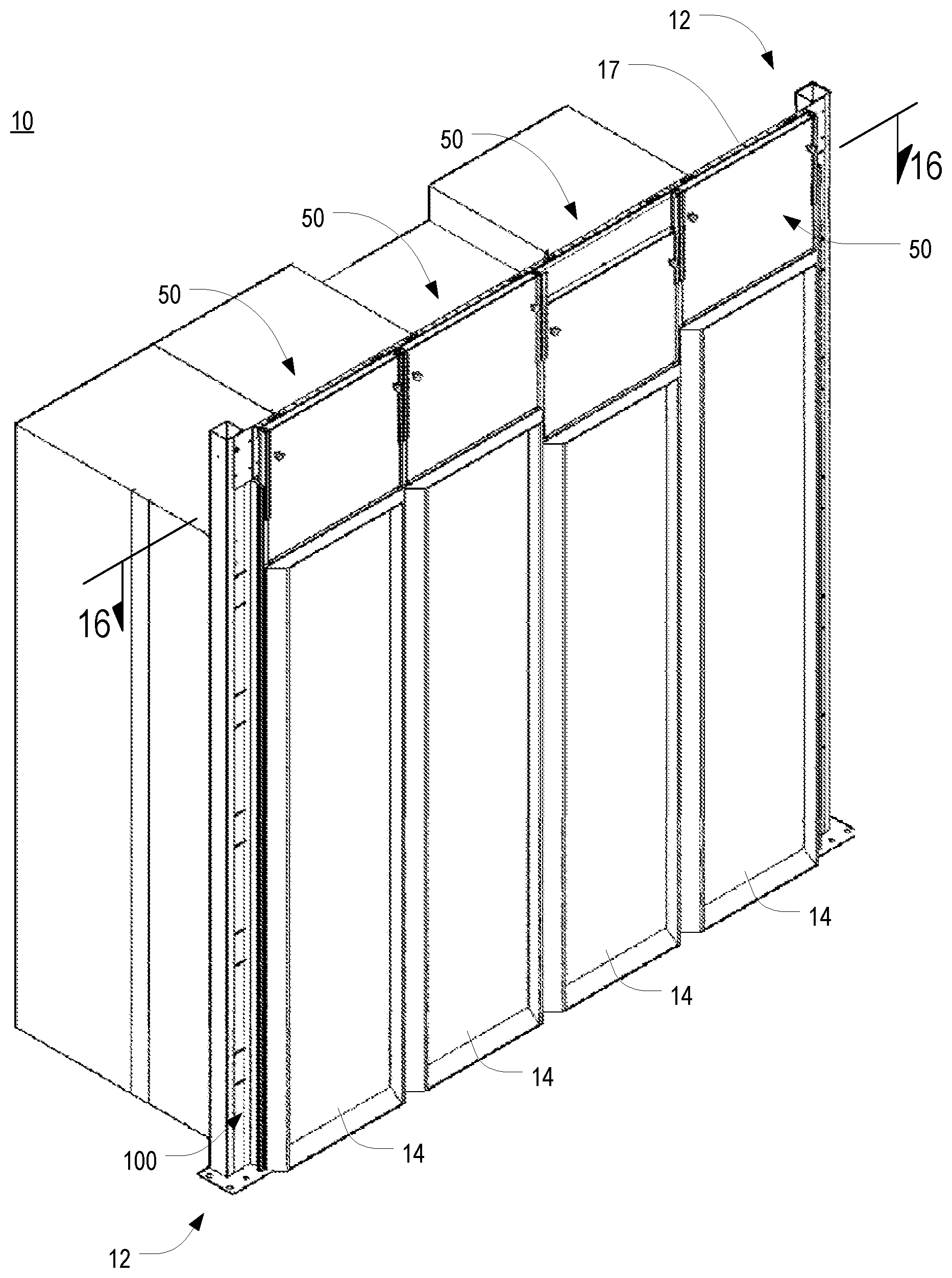
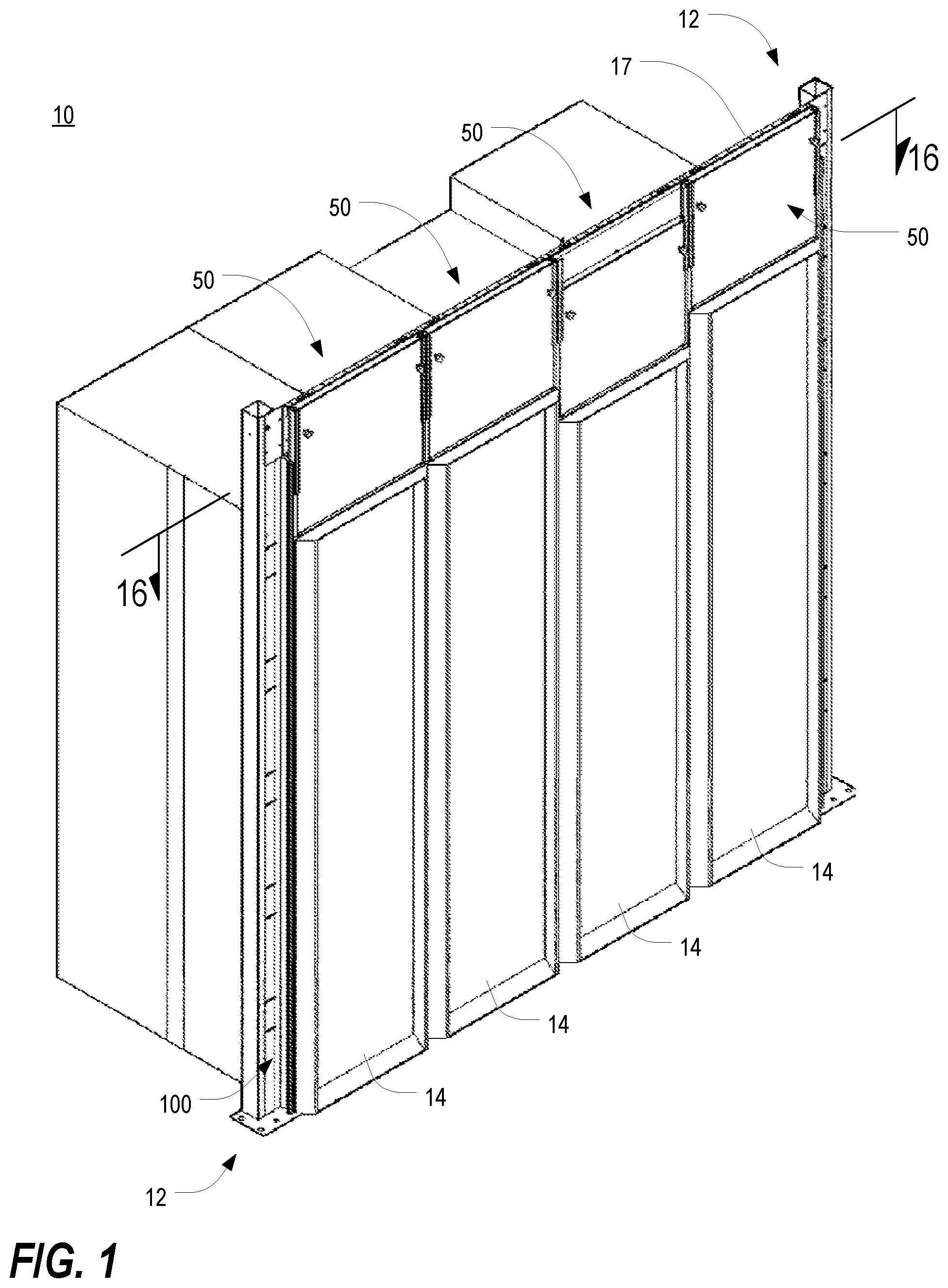
[0054] FIG. 1 is an isometric view of a hot/cold aisle containment system in use with a row of electronic equipment enclosures in accordance with a preferred embodiment of the present invention;
[0055] FIG. 2 is an isometric view of the frame structure of FIG. 1;
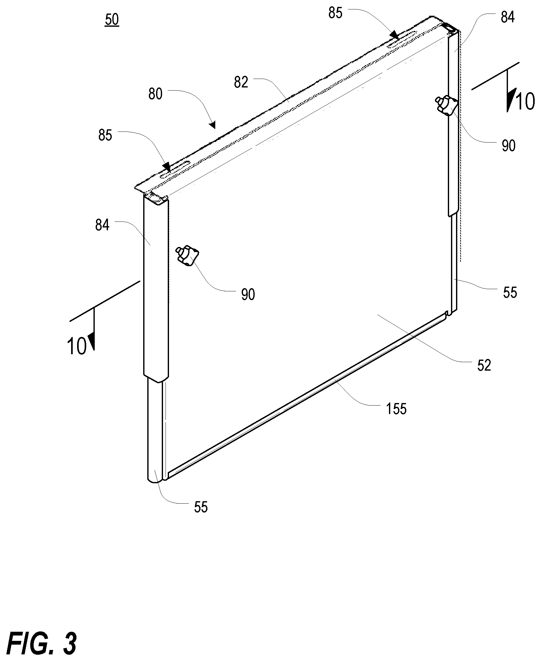
[0056] FIG. 3 is an isometric view of one of the header panel assemblies of FIG. 1;
[0057] FIG. 4 is a reverse isometric view of the header panel assembly of FIG. 3;
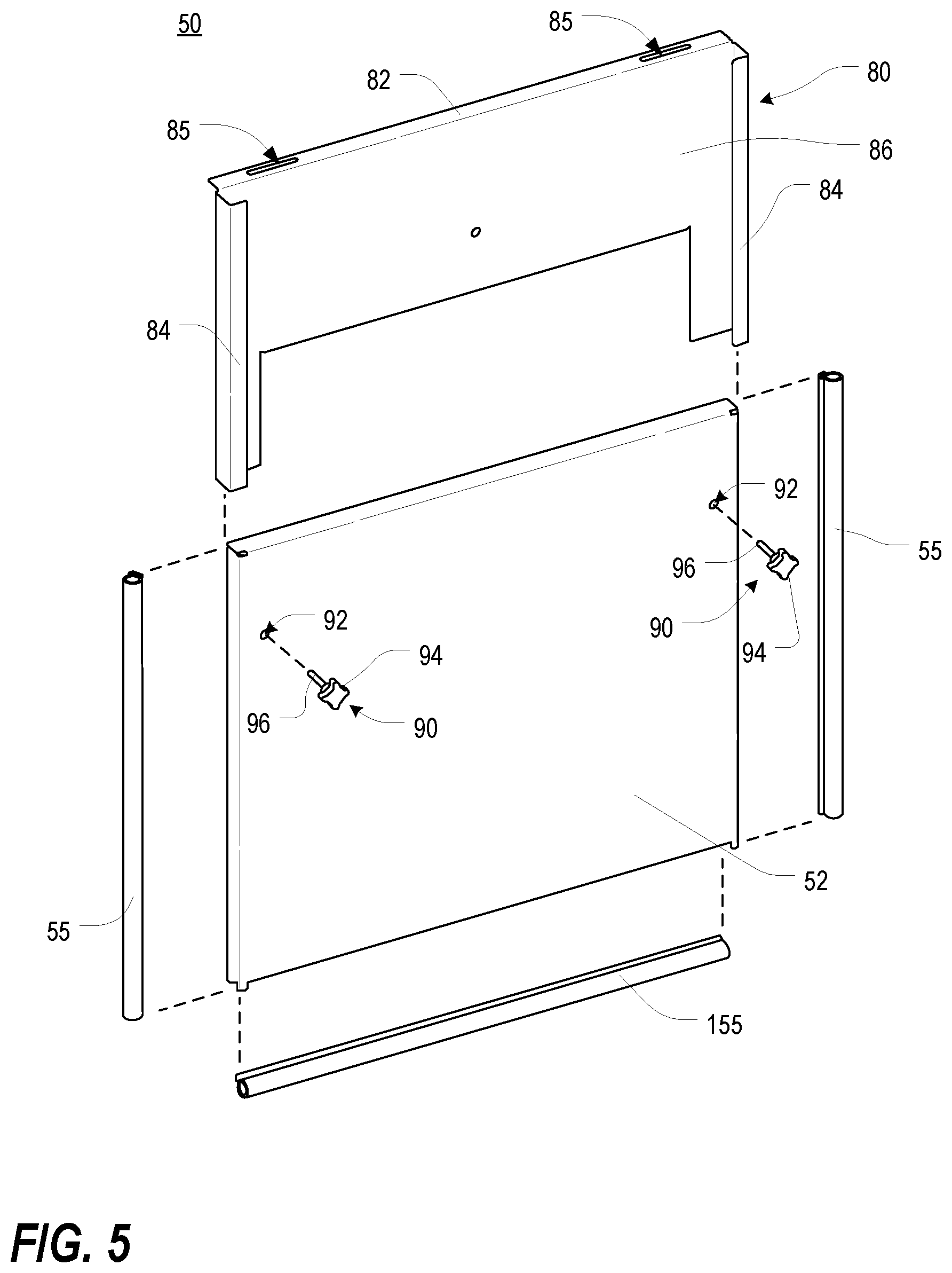
[0058] FIG. 5 is an orthogonal exploded view of the header panel assembly of FIG. 3;
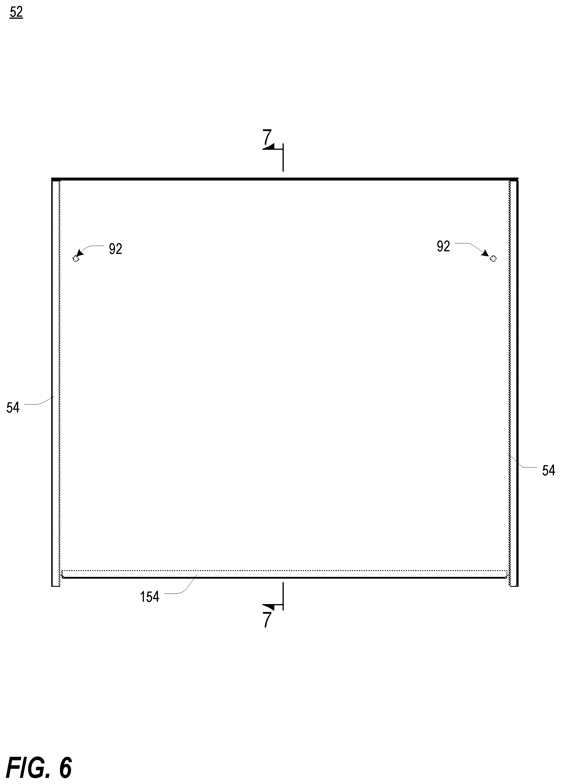
[0059] FIG. 6 is a rear plan view of the main header panel of FIG. 3;
[0060] FIG. 7 is an end cross-sectional view of the main panel of FIG. 6, taken along line 7-7;
[0061] FIG. 8 is a bottom view of the main panel of FIG. 6;
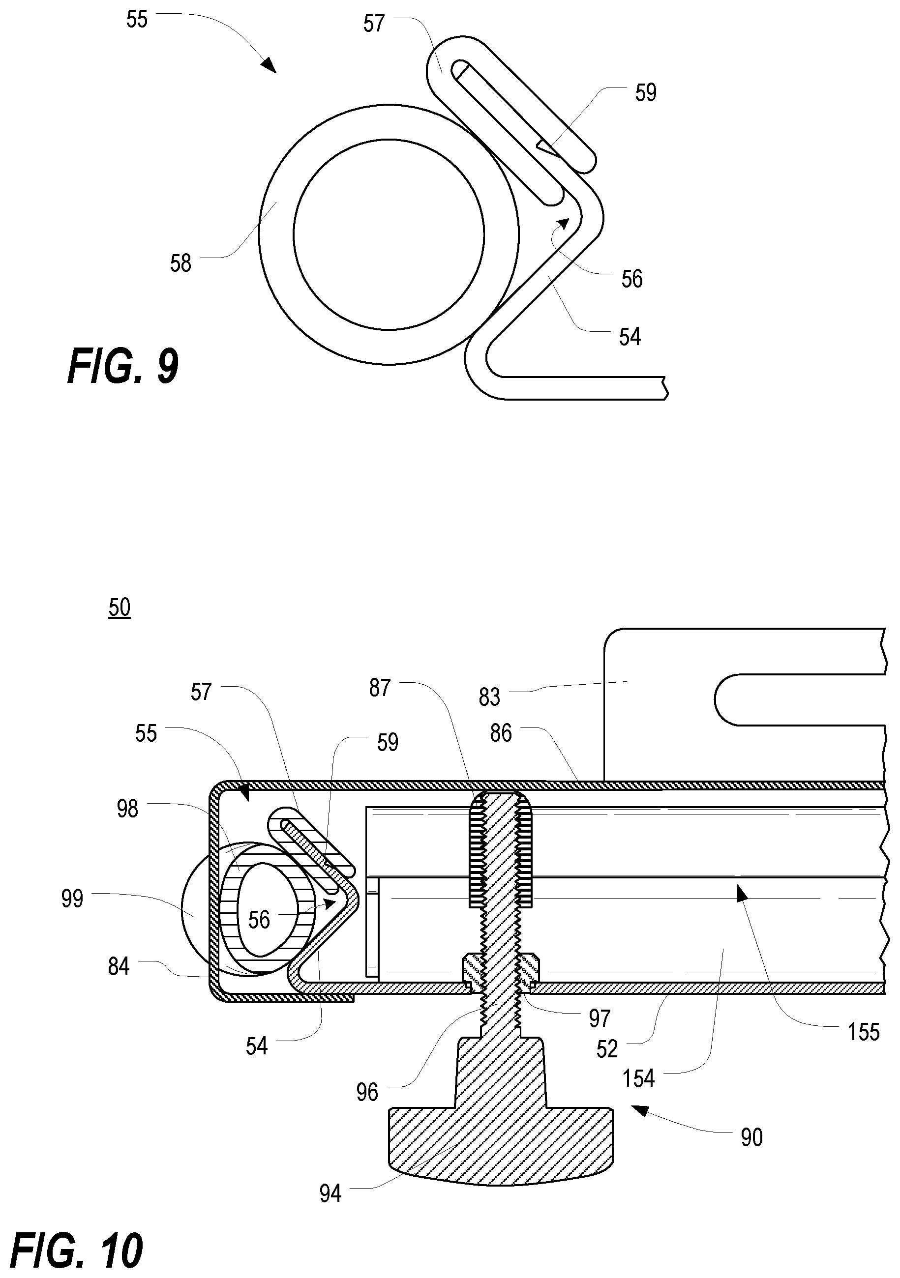
[0062] FIG. 9 is a schematic view of a seal mounted in one of the V-shaped grooves of the main header panel of FIG. 6;
[0063] FIG. 10 is a fragmentary top cross-sectional view of the left edge of the header panel assembly of FIG. 3, taken along line 10-10;
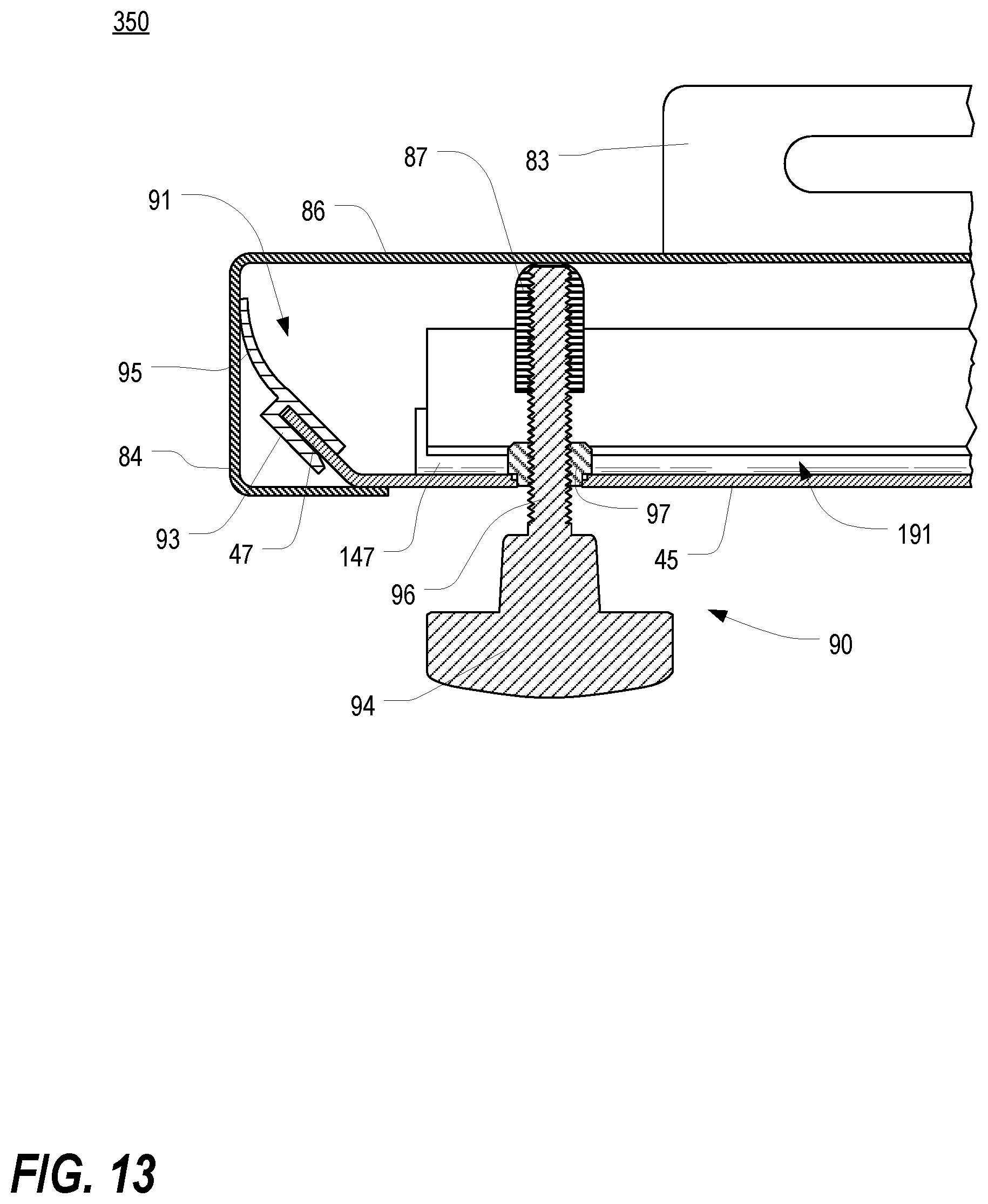
[0064] FIGS. 11-13 are fragmentary top cross-sectional views, similar to that of FIG. 10, of the left edge of various alternative header panel assembly embodiments;
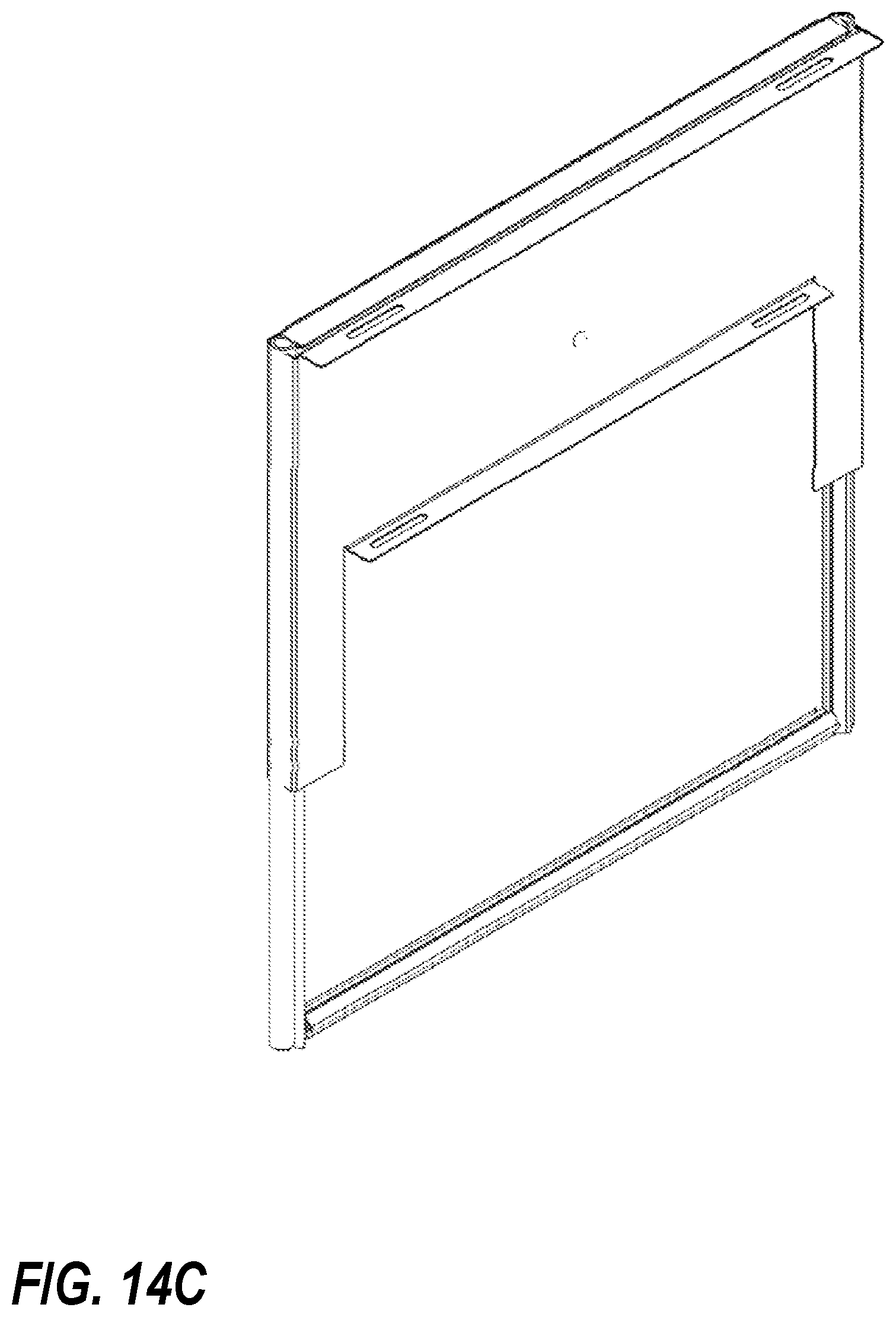
[0065] FIGS. 14A-14C are isometric views of header panel assemblies similar to that of FIG. 3 but having different vertical dimensions;
[0066] FIG. 15 is an isometric view of one of the side seal assemblies of FIG. 1;
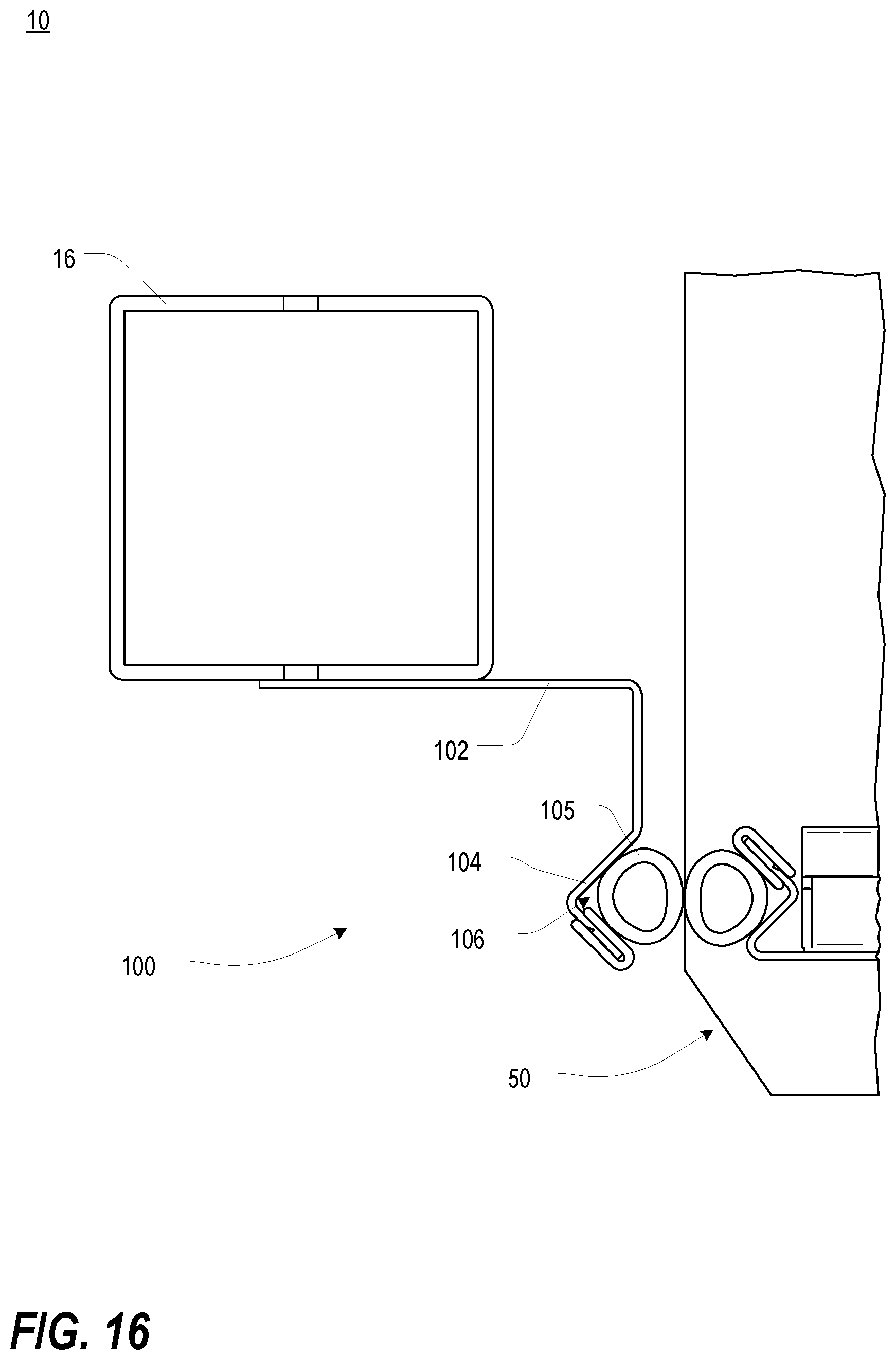
[0067] FIG. 16 is a fragmentary top cross-sectional view of the left end of the hot/cold aisle containment system of FIG. 1, taken along line 16-16, illustrating the interface between a header panel assembly and a side seal assembly;
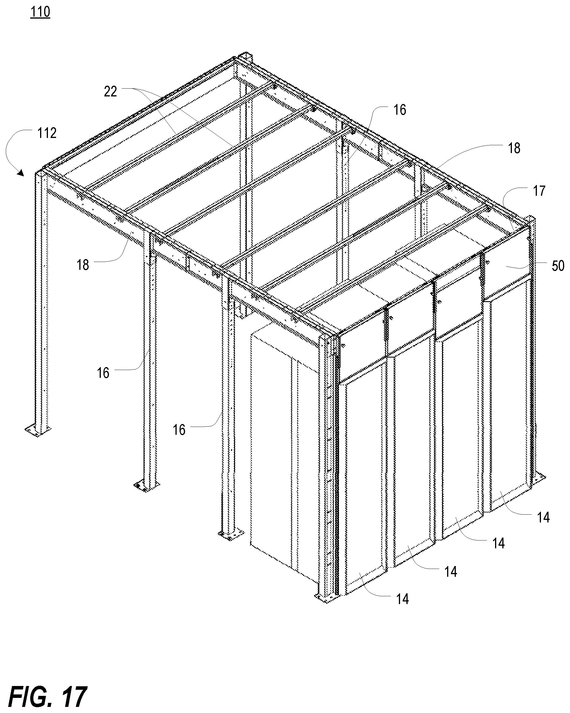
[0068] FIG. 17 is an isometric view of a hot/cold aisle containment system in use with a row of electronic equipment enclosures in accordance with another preferred embodiment of the present invention;
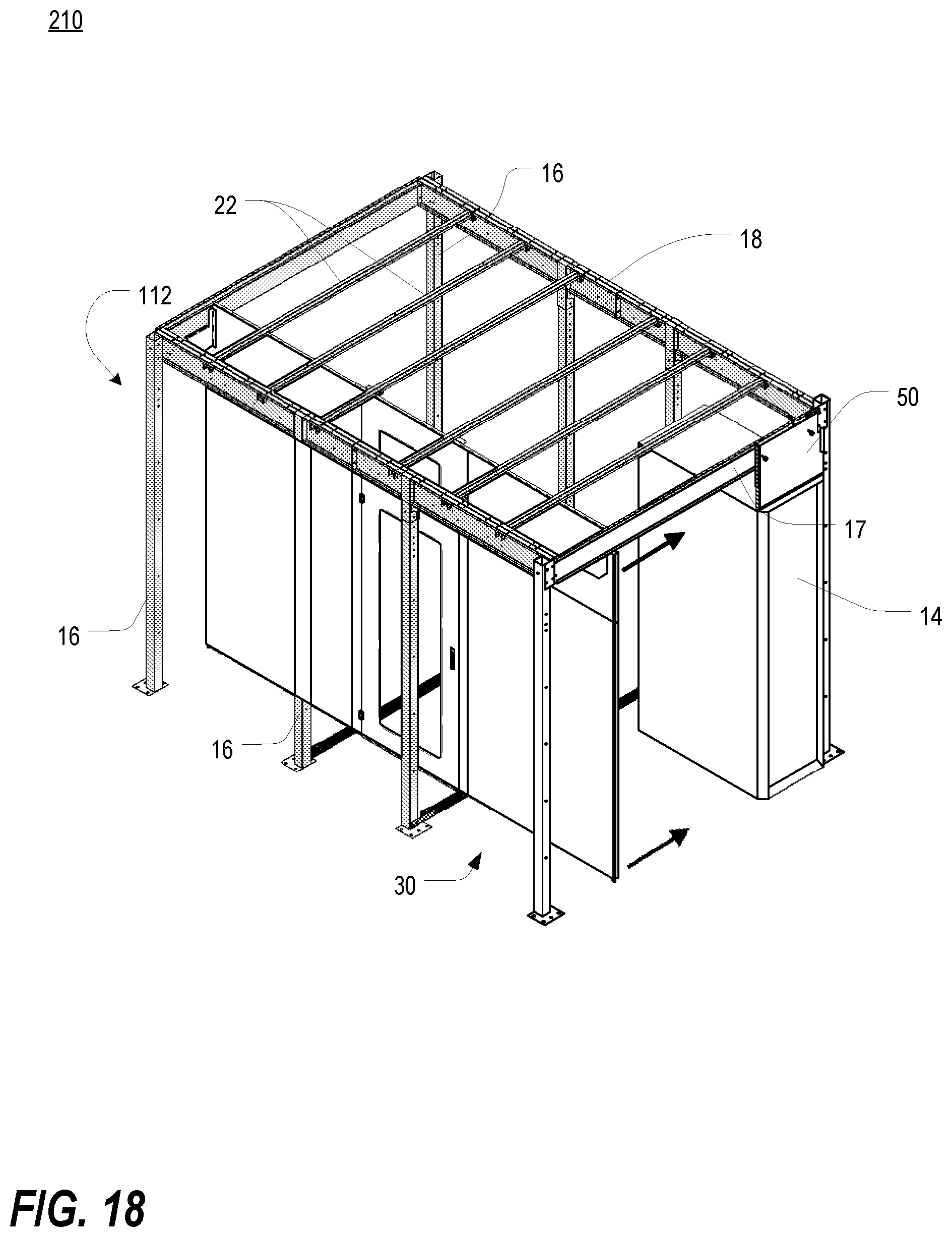
[0069] FIG. 18 is an isometric view of a hot/cold aisle containment system in use with an electronic equipment enclosure installed at one side thereof and an adjustable wall assembly temporarily positioned away from the enclosure in accordance with still another preferred embodiment of the present invention;
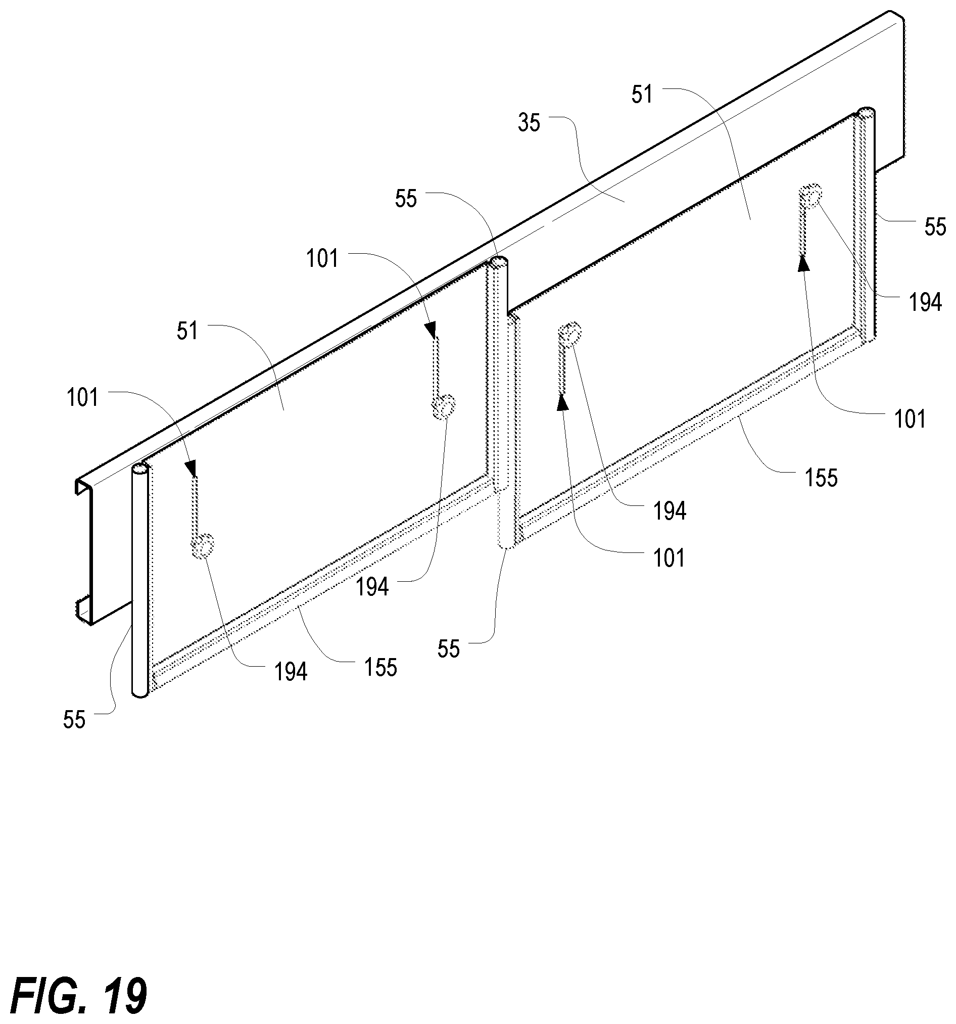
[0070] FIG. 19 is an isometric view of an overhanging beam for use in a hot/cold aisle containment system, shown with a pair of adjustable header panels attached thereto; and
[0071] FIG. 20 is a fragmentary top view of adjacent edges of the pair of adjustable header panels of FIG. 19.
DETAILED DESCRIPTION
[0072] As a preliminary matter, it will readily be understood by one having ordinary skill in the relevant art ("Ordinary Artisan") that the present invention has broad utility and application. Furthermore, any embodiment discussed and identified as being "preferred" is considered to be part of a best mode contemplated for carrying out the present invention. Other embodiments also may be discussed for additional illustrative purposes in providing a full and enabling disclosure of the present invention. As should be understood, any embodiment may incorporate only one or a plurality of the above-disclosed aspects of the invention and may further incorporate only one or a plurality of the above-disclosed features. Moreover, many embodiments, such as adaptations, variations, modifications, and equivalent arrangements, will be implicitly disclosed by the embodiments described herein and fall within the scope of the present invention.
[0073] Accordingly, while the present invention is described herein in detail in relation to one or more embodiments, it is to be understood that this disclosure is illustrative and exemplary of the present invention, and is made merely for the purposes of providing a full and enabling disclosure of the present invention. The detailed disclosure herein of one or more embodiments is not intended, nor is to be construed, to limit the scope of patent protection afforded the present invention, which scope is to be defined by the claims and the equivalents thereof. It is not intended that the scope of patent protection afforded the present invention be defined by reading into any claim a limitation found herein that does not explicitly appear in the claim itself.
[0074] Thus, for example, any sequence(s) and/or temporal order of steps of various processes or methods that are described herein are illustrative and not restrictive. Accordingly, it should be understood that, although steps of various processes or methods may be shown and described as being in a sequence or temporal order, the steps of any such processes or methods are not limited to being carried out in any particular sequence or order, absent an indication otherwise. Indeed, the steps in such processes or methods generally may be carried out in various different sequences and orders while still falling within the scope of the present invention. Accordingly, it is intended that the scope of patent protection afforded the present invention is to be defined by the appended claims rather than the description set forth herein.
[0075] Additionally, it is important to note that each term used herein refers to that which the Ordinary Artisan would understand such term to mean based on the contextual use of such term herein. To the extent that the meaning of a term used herein--as understood by the Ordinary Artisan based on the contextual use of such term--differs in any way from any particular dictionary definition of such term, it is intended that the meaning of the term as understood by the Ordinary Artisan should prevail.
[0076] Regarding applicability of 35 U.S.C. .sctn. 112, 6, no claim element is intended to be read in accordance with this statutory provision unless the explicit phrase "means for" or "step for" is actually used in such claim element, whereupon this statutory provision is intended to apply in the interpretation of such claim element.
[0077] Furthermore, it is important to note that, as used herein, "a" and "an" each generally denotes "at least one," but does not exclude a plurality unless the contextual use dictates otherwise. Thus, reference to "a picnic basket having an apple" describes "a picnic basket having at least one apple" as well as "a picnic basket having apples." In contrast, reference to "a picnic basket having a single apple" describes "a picnic basket having only one apple."
[0078] When used herein to join a list of items, "or" denotes "at least one of the items," but does not exclude a plurality of items of the list. Thus, reference to "a picnic basket having cheese or crackers" describes "a picnic basket having cheese without crackers," "a picnic basket having crackers without cheese," and "a picnic basket having both cheese and crackers." Finally, when used herein to join a list of items, "and" denotes "all of the items of the list." Thus, reference to "a picnic basket having cheese and crackers" describes "a picnic basket having cheese, wherein the picnic basket further has crackers," as well as describes "a picnic basket having crackers, wherein the picnic basket further has cheese."
[0079] Referring now to the drawings, in which like numerals represent like components throughout the several views, the preferred embodiments of the present invention are next described. The following description of one or more preferred embodiment(s) is merely exemplary in nature and is in no way intended to limit the invention, its application, or uses.
[0080] FIG. 1 is an isometric view of a hot/cold aisle containment system 10 in use with a row of electronic equipment enclosures 14 in accordance with a preferred embodiment of the present invention. As shown therein, the containment system 10 includes a frame structure 12, a plurality of header panel assemblies 50 and a pair of side seal assemblies 100. Each of these will be discussed in greater detail hereinbelow. Enclosures suitable for use with preferred embodiments of the present invention are described and illustrated in commonly-assigned U.S. Pat. Nos. 5,997,117; 6,185,098; 7,697,285; 7,804,685; U.S. Patent Application Publication No. US 2009/0227197 A1; and U.S. Patent Application Publication No. US 2010/0172092 A1, the entirety of each of which is incorporated herein by reference.
[0081] FIG. 2 is an isometric view of the frame structure 12 of FIG. 1. As shown therein, the frame structure 12 includes a pair of vertical posts 16 and a horizontal beam 17.
[0082] FIG. 3 is an isometric view of one of the header panel assemblies 50 of FIG. 1; FIG. 4 is a reverse isometric view of the header panel assembly 50 of FIG. 3; and FIG. 5 is an orthogonal exploded view of the header panel assembly 50 of FIG. 3. As shown therein, each header panel assembly 50 includes a main panel 52, a fixed bracket 80, a pair of clamps 90, and a plurality of seals 55,155. As perhaps best shown in FIGS. 4 and 5, the fixed bracket 80 includes a top mounting flange 82, a bottom mounting flange 83 and two side retention flanges 84, all extending from a main body 86. The top and bottom mounting flanges 82,83 facilitate attachment to the horizontal beam 17 of the frame structure 12. Lateral adjustment along the horizontal beam may be facilitated by slots 85 in the mounting flanges 82,83. The side retention flanges 84 are adapted to receive the main panel 52 as more fully described hereinbelow.
[0083] FIG. 6 is a rear plan view of the main header panel 52 of FIG. 3, while FIG. 7 is an end cross-sectional view of the main panel 52 of FIG. 6, taken along line 7-7, and FIG. 8 is a bottom view of the main panel 52 of FIG. 6. As shown therein, the main panel 52 includes V-shaped flanges 54,154 along the sides and bottom thereof. Each V-shaped flange 54,154 defines a groove 56,156 of corresponding shape. These grooves 56,156 are adapted to receive and retain a respective seal 55,155. In this regard, FIG. 9 is a schematic view of a seal 55 mounted in one of the V-shaped grooves 56 of the main header panel 52 of FIG. 6. It will be appreciated that the seals 55,155 may have any of a wide range of different shapes and configurations and may be comprised of any of a wide range of different materials. In contemplated embodiments, the seal may be a gasket, a brush, a wiper blade, or a compressible bumper. As seen in cross-section, each seal 55,155 includes a mounting portion 57 and a body portion 58, wherein the mounting portion 57 is adapted to attach to the edge of the V-shaped flanges 54,154. Bosses 59 may be provided to assist in such attachment. The body portion 58 is large enough to extend well outside of the V-shaped groove 56,156 and is comprised of a compressible material of any type conventionally utilized for gaskets, seals, brushes or the like.
[0084] When the main panel 52 is positioned within the side retention flanges 84 of the fixed bracket 80, the side seals 55 are partially trapped within the side V-shaped flanges 54 by the retention flanges 84. This is illustrated in FIG. 10, which is a fragmentary top cross-sectional view of the left edge of the header panel assembly 50 of FIG. 3, taken along line 10-10. As shown therein, the upper end 98 of the seal 55 is compressed into the V-shaped groove 56 by the retention flange 84, while the lower end 99 of the seal 55 remains uncompressed. It will be appreciated, however, that when the header panel assembly 50 is properly installed in place next to another header panel assembly 50, a side seal assembly or another structure, the lower end 99 of the seal 55 will usually be compressed as well, thereby sealing the header panel assembly 50 against the respective structure.
[0085] Referring again to FIG. 6, it will be appreciated that the lower ends of the side flanges 54 extend below the bottom of the main panel 52, and thus below the bottom flange 154. This arrangement permits the bottom seal 155 to be placed within the bottom groove 156 such that it may be generally aligned with the lower end of the side flanges 54, thereby helping to ensure a complete seal across the bottom of the assembly 50. This is at least partially illustrated in FIG. 3.
[0086] With reference to FIGS. 3, 5 and 10, it will be appreciated that the body of the main panel 52 is penetrated by two clamp apertures 92 adapted to receive the clamps 90. In at least some embodiments, the clamps 90 each include a handle 94 and a threaded shaft 96, and a threaded nut 97 is attached behind and around each aperture 92. In other embodiments, the apertures 92 may themselves be threaded, or may comprise sheet metal or the like into which threads may be created by screwing the threaded clamp shaft 96 therethrough. As will be appreciated, the main header panel 52 may be held in place against the fixed bracket 80 by screwing the clamp shafts 96 through the apertures 92 in the panel 52 until the ends of the shafts 96 are forced against the main body 86 of the fixed bracket 80. In order to preserve structural integrity of the main body 86 of the fixed bracket 80, the end of the shafts 96 may be fitted with protective end caps 87. While clamps 90 are shown in the drawings, it is contemplated that a wide range of mechanisms may be used to hold the main panel 52 in place against the fixed bracket 80. In particular, it is contemplated that cam locks, spring fasteners or any of a range of other mechanisms may be implemented to accomplish the clamping function.
[0087] Use of the header panel assembly 50 may perhaps be best understood with reference to FIGS. 1 and 10. Each header panel assembly 50 may be installed directly above a respective electronic equipment enclosure 14 to fill the space between the top of the enclosure 14 and the frame structure 12 or other structure above it. The vertical length of each header panel assembly 50 may be adjusted by loosening the clamps 90 and sliding the main header panel 52 up or down relative to the fixed bracket 80 before retightening the clamps 90. The clamp arrangement permits the infinite adjustment of the vertical position of the main header panel 52 relative to its fixed bracket 80 (within a range determined by the dimensions of the panel 52 and bracket 80), and thus allows the header panel assembly 50 to be custom adjusted to fit the space between the top of the respective enclosure 14 and the frame structure 12. When installed above the enclosure 14, the header panel assembly 50 thus blocks the space above the enclosure 14 and prevents recirculation of heated air from the rear of the enclosure 14 over the top thereof where it could mingle with the cooling air being provided to the enclosure front.
[0088] The infinite adjustability (within the dimensional range) ensures that air gaps may be substantially entirely eliminated, and differences in enclosure heights managed effectively. This is illustrated, for example, in FIG. 1, where three enclosures 14 have the same approximate height, while a fourth (the second from the right), is shorter than the other three. The header panel assemblies 50 for the first three are all adjusted to be the same length, while the header panel assembly 50 for the fourth enclosure 14 is lengthened to ensure that the bottom of the main panel 52 extends to the top of the enclosure 14 with the bottom seal 155 being compressed between the bottom V-shaped flange 154 and the top of the enclosure 14.
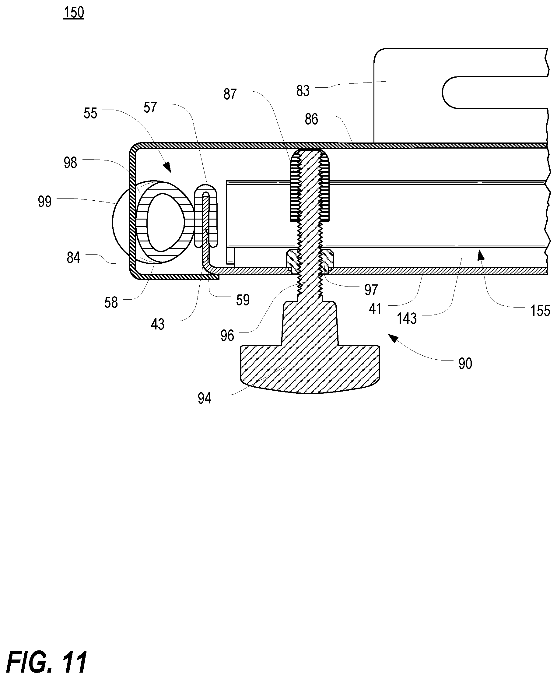
[0089] FIGS. 11-13 are fragmentary top cross-sectional views, similar to that of FIG. 10, of the left edge of various alternative embodiments of header panel assemblies. As shown in FIGS. 11-13, flanges on the main panel may have any of a variety of different shapes and configurations. For instance, in FIG. 11, rather than V-shaped flanges, a main panel 41 of a header panel assembly 150 includes generally perpendicular flanges 43,143 along the sides and bottom thereof. Each perpendicular flange 43,143 defines an outer edge to accommodate and retain a respective seal 55,155. As in the embodiment depicted in FIG. 10, each seal 55,155 includes a mounting portion 57 adapted to attach to the edge of the perpendicular flange 43,143. Bosses 59 may be provided to assist in such attachment. Each seal 55,155 further includes a body portion 58 comprised of a compressible material of any type conventionally utilized for gaskets, seals, brushes or the like. When the main panel 41 is positioned within the side retention flanges 84 of the fixed bracket 80, the seals 55,155 extend from the edges of the main panel 41 and are in a position to abut an adjacent structure, thereby forming a seal therewith. As shown therein, the upper end 98 of the seal 55 is compressed into the V-shaped groove 56 by the retention flange 84, while the lower end 99 of the seal 55 remains uncompressed. It will be appreciated, however, that when the header panel assembly 150 is properly installed in place next to another header panel assembly 150, a side seal assembly or another structure, the lower end 99 of the seal 55 will usually be compressed as well, thereby sealing the header panel assembly 150 against the respective structure.
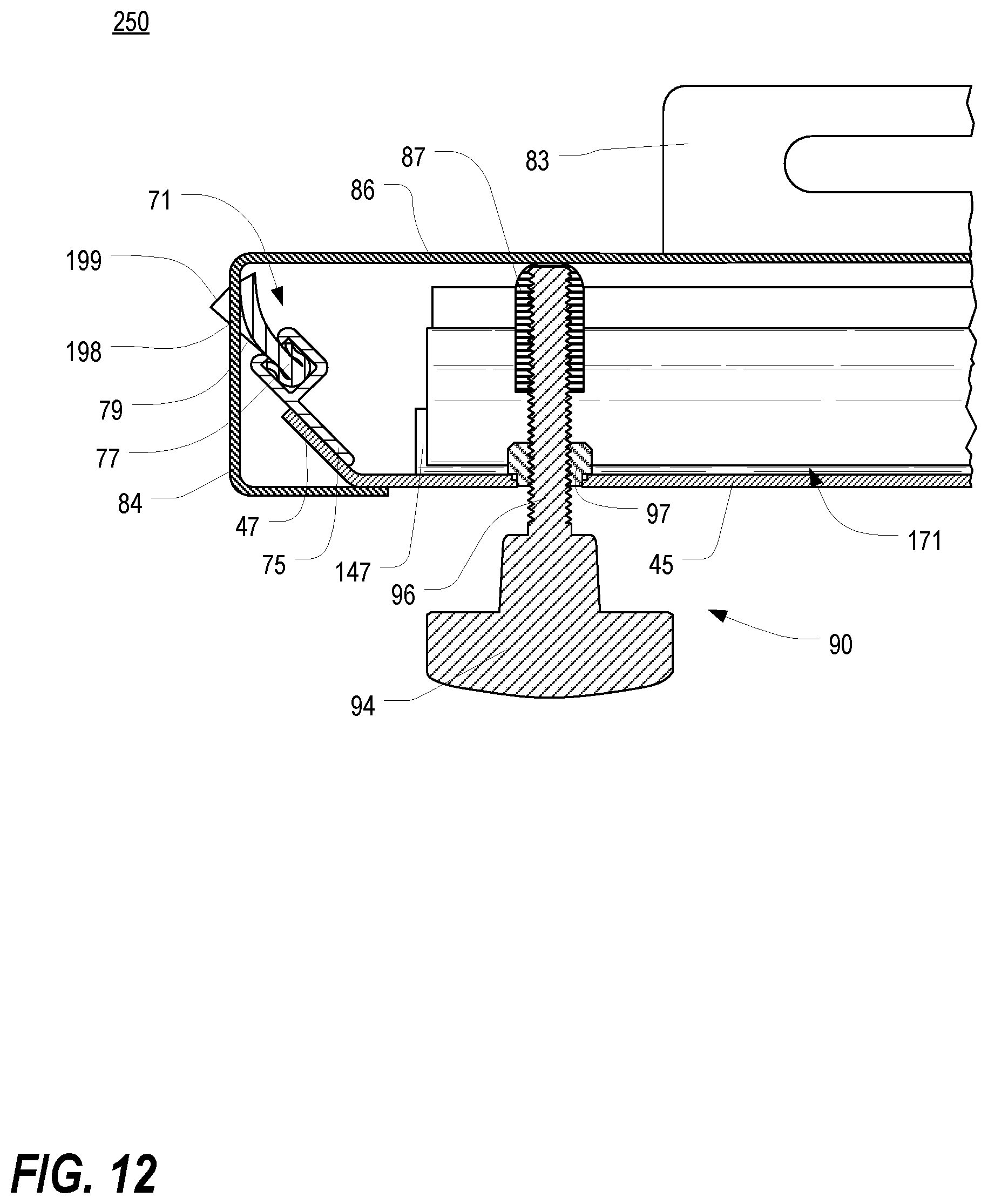
[0090] In FIG. 12, a main panel 45 of a header panel assembly 250 includes flanges 47,147 at the sides and bottom thereof that extend away from the main panel 45 at an angle. Each angled flange 47,147 defines an outer edge to which a respective brush seal 71,171 is attached. Each brush seal 71,171 includes a cradle portion 75 that attaches along the outer edge of the angled flanges 47,147 and a brush portion 77 that is adapted to be snap-fit into the cradle portion 75. Bristles 79 of the brush portion 77 extend away from the main panel 45 and are in a position to abut an adjacent structure, thereby forming a seal therewith. As shown in FIG. 12, bristles 79 at the upper end 198 of the brush seal 71 are deflected by the retention flange 84 while bristles 79 at the lower end 199 of the brush seal 71 remain undeflected. It will be appreciated, however, that when the header panel assembly 250 is properly installed in place next to another header panel assembly, a side seal assembly or another structure, the lower end 199 of the brush seal 71 will usually be deflected as well, thereby sealing the header panel assembly 250 against the respective structure.
[0091] In FIG. 13, the main panel 45 of a header panel assembly 350 includes flanges 47,147 at the sides and bottom thereof that extend away from the main panel 45 at an angle. Each angled flange 47,147 defines an outer edge to which a respective deflectable blade seal 91,191 is attached. Each blade seal 91,191 includes an attachment portion 93 that is adapted to fittingly accommodate an outer edge of a corresponding angled flange 47,147. Each blade seal 91,191 further includes a blade portion 95 that extends away from the main panel 45 and is in a position to abut an adjacent structure so as to form a seal therewith. As shown in FIG. 13, the blade portion 95 is deflected by, and forms a seal against, the retention flange 84. It will also be appreciated that when the header panel assembly 350 is properly installed in place next to another header panel assembly, a side seal assembly or another structure, any portion of the blade seal 91 that extends below the retention flange 84 would likewise be deflected by an adjacent structure and, thus, capable of sealing the header panel assembly 350 against the respective structure.
[0092] In at least some commercial embodiments, header panel assemblies 50 of different vertical dimensions are provided to accommodate enclosures 14 and frame structures 12 or other structures of different sizes. For example, FIGS. 14A-14C are isometric views of header panel assemblies similar to that of FIG. 3 but having different vertical dimensions. It will also be appreciated that different widths may likewise be provided.
[0093] Air sealing along the sides of electronic equipment enclosures 14 at the ends of the row of enclosures 14 may be facilitated by the side seal assemblies 100. FIG. 15 is an isometric view of one of the side seal assemblies 100 of FIG. 1. As shown therein, each side seal assembly 100 includes a vertical support bracket 102 and a seal 105. The vertical support bracket 102 may be attached to a vertical post 16 of the frame structure 12, or other structure, via a plurality of horizontal slots 108. The slots facilitate lateral adjustment along the width of the vertical post 16.
[0094] FIG. 16 is a fragmentary top cross-sectional view of the left end of the hot/cold aisle containment system 10 of FIG. 1, taken along line 16-16, illustrating the interface between a header panel assembly 50 and a side seal assembly 100. As shown therein, the vertical support bracket 102 includes a V-shaped flange 104, similar in cross-section to the V-shaped flanges 54,154 of the main header panel 52, which defines a groove 106 of corresponding shape. The groove 106 is adapted to receive a seal 105 which is also of similar cross-section and material to the seals 55,155 of the header panel assembly 50. As shown therein, the seal 105 of the side seal assembly 100 is compressed by and against the side seal 55 of the adjacent header panel assembly 50 and also by the body of the electronic equipment enclosure 14 below. In combination with the vertical support bracket 102, the seal 105 of the side seal assembly 100 thus provides top-to-bottom sealing between both the leftmost enclosure 14 of FIG. 1 and the leftmost header panel assembly 50. It will be appreciated that the vertical support bracket 102 may be adjusted laterally, as described previously, to customize the spacing between the V-shaped flange 104 and the enclosure 14/header panel assembly 50. While a compressible seal is depicted in FIGS. 15 and 16, it is contemplated that a wide variety of different seals, including brush seals and deflectable blade seals, may be used in connection with the side seal assembly 100. Furthermore, while the flanges 54,154 are shown as V-shaped, it is contemplated that the flanges 54,154 may have any of a wide variety of different shapes and configurations, including generally perpendicular flanges and angled flanges.
[0095] When installed next to an enclosure 14 and the header panel assembly 50 above it, the side seal assembly 100 thus blocks the space between the enclosure 14 and the vertical post 16 and prevents recirculation of heated air from the rear of the enclosure 14 around the side thereof where it could mingle with the cooling air being provided to the enclosure front.
[0096] FIG. 17 is an isometric view of a hot/cold aisle containment system 110 in use with a row of electronic equipment enclosures 14 in accordance with another preferred embodiment of the present invention. In particular, the containment system 110 of FIG. 17 includes a larger and more comprehensive frame structure 112 adapted to receive and support various panels and other structures to more fully enclose a hot aisle behind the enclosures 14. This frame structure 112, which includes additional vertical posts 16 and horizontal beams 17,18 as well as a plurality of horizontal joists 22. Frame structures 112 suitable for use with header panel assemblies 50 in accordance with one or more preferred embodiments of the present invention are described in commonly-assigned U.S. provisional patent application 61/411,359, entitled, "ADJUSTABLE WALL ASSEMBLY FOR HOT/COLD AISLE CONTAINMENT SYSTEM," a copy of which is attached as Appendix A, which is expressly incorporated by reference herein in its entirety.
[0097] One example of an assembly of panels to form a wall is shown in FIG. 18, which is an isometric view of a hot/cold aisle containment system 210 in use with an electronic equipment enclosure 14 and an adjustable wall assembly 30 in accordance with still another preferred embodiment of the present invention. The enclosure 14 is installed at one end of the frame structure 112 and the adjustable wall assembly 30 is temporarily positioned away from the enclosure 14 but can be moved toward the enclosure 14 to seal off the front end of the enclosure and the space behind it. Adjustable wall assemblies suitable for use with the frame structure 112 and header panel assemblies 50 in accordance with one or more preferred embodiments of the present invention are described in the aforementioned '359 patent application, attached as Appendix A.
[0098] FIG. 19 is an isometric view of an overhanging beam 35 for use in a hot/cold aisle containment system, shown with a pair of adjustable header panels 51 attached thereto. FIG. 20 is a fragmentary top view of adjacent edges of the pair of adjustable header panels 51 of FIG. 19. An overhanging beam 35 may be mounted horizontally in a containment system having a row of enclosures to provide another sealing option. As shown in FIG. 19, the overhanging beam 35 accommodates one or more header panels 51, each of which includes one or more adjustment slots 101. The header panels 51 are mounted directly to the overhanging beam 35 via clamps 194, each extending through a respective adjustment slot 101 of the header panel 51 and into a respective clamp aperture (not illustrated) of the overhanging beam 35. The clamps 194 permit the header panel 51 to be adjusted vertically relative to the overhanging beam 35. By loosening the clamps 194 of a selected one of the header panels 51, the header panel 35 has infinite adjustability (within the dimensional range allowed by the adjustment slots 101). Tightening the clamps 194 fixes the header panel 35 into any desired position.
[0099] Each header panel 51 is generally flat with generally perpendicular flanges 53,153 along the sides and bottom thereof. Each perpendicular flange 53,153 defines an outer edge to accommodate and retain a respective seal 55,155. Each seal 55,155 includes a mounting portion 57 adapted to attach to the edge of the perpendicular flange 53,153. Bosses (not illustrated) may be provided to assist in such attachment. Each seal 55,155 further includes a body portion 58 comprised of a compressible material of any type conventionally utilized for gaskets, seals, brushes or the like. While a compressible seal is depicted in FIGS. 19 and 20, it is contemplated that a wide variety of different seals, including brush seals and deflectable blade seals, may be used in connection with the header panels 51. Furthermore, while the flanges 53,153 are shown as generally perpendicular, it is contemplated that the flanges 53,153 may have any of a wide variety of different shapes and configurations, including V-shaped flanges and angled flanges. The seals 55,155 extend from the edges of the header panel 51 and are in a position to abut an adjacent structure so as to form a seal therewith. As shown in FIG. 20, the seals 55 of adjacent header panels 51 abut one another, thereby compressing the body portions 58 of each seal 55 and sealing off the boundary between adjacent header panels 51.
[0100] When installed above an enclosure 14 in a containment system and adjusted into position against the enclosure 14, the header panel 51 can effectively block the space above the enclosure 14 and prevent recirculation of heated air from the rear of the enclosure 14 over the top thereof where it could mingle with the cooling air being provided to the enclosure front. With multiple header panels 51 installed, the header panels 51 not only establish a seal with one another but may also be selectively adjusted to different heights, as depicted in FIG. 19, so as to accommodate varying heights among the enclosures installed in the containment system. The infinite adjustability (within the dimensional range) ensures that air gaps may be substantially entirely eliminated, and differences in enclosure heights managed effectively. Furthermore, by mounting the header panels 51 directly to the overhanging beam 35, the need for a separate telescoping panel to accompany the header panel 51 may be avoided.
[0101] Based on the foregoing information, it will be readily understood by those persons skilled in the art that the present invention is susceptible of broad utility and application. Many embodiments and adaptations of the present invention other than those specifically described herein, as well as many variations, modifications, and equivalent arrangements, will be apparent from or reasonably suggested by the present invention and the foregoing descriptions thereof, without departing from the substance or scope of the present invention.
[0102] Accordingly, while the present invention has been described herein in detail in relation to one or more preferred embodiments, it is to be understood that this disclosure is only illustrative and exemplary of the present invention and is made merely for the purpose of providing a full and enabling disclosure of the invention. The foregoing disclosure is not intended to be construed to limit the present invention or otherwise exclude any such other embodiments, adaptations, variations, modifications or equivalent arrangements; the present invention being limited only by the claims appended hereto and the equivalents thereof.
* * * * *
D00000
D00001
D00002
D00003
D00004
D00005
D00006
D00007
D00008
D00009
D00010
D00011
D00012

D00013

D00014
D00015

D00016
D00017
D00018
D00019
D00020

XML
uspto.report is an independent third-party trademark research tool that is not affiliated, endorsed, or sponsored by the United States Patent and Trademark Office (USPTO) or any other governmental organization. The information provided by uspto.report is based on publicly available data at the time of writing and is intended for informational purposes only.
While we strive to provide accurate and up-to-date information, we do not guarantee the accuracy, completeness, reliability, or suitability of the information displayed on this site. The use of this site is at your own risk. Any reliance you place on such information is therefore strictly at your own risk.
All official trademark data, including owner information, should be verified by visiting the official USPTO website at www.uspto.gov. This site is not intended to replace professional legal advice and should not be used as a substitute for consulting with a legal professional who is knowledgeable about trademark law.