Wireless Sensor Communication System For Enclosures
Gundel; Douglas B. ; et al.
U.S. patent application number 16/473711 was filed with the patent office on 2019-11-14 for wireless sensor communication system for enclosures. The applicant listed for this patent is 3M INNOVATIVE PROPERTIES COMPANY. Invention is credited to Douglas B. Gundel, Ernesto M. Rodriguez, Jr..
| Application Number | 20190349727 16/473711 |
| Document ID | / |
| Family ID | 62790967 |
| Filed Date | 2019-11-14 |


| United States Patent Application | 20190349727 |
| Kind Code | A1 |
| Gundel; Douglas B. ; et al. | November 14, 2019 |
WIRELESS SENSOR COMMUNICATION SYSTEM FOR ENCLOSURES
Abstract
A wireless sensor communication system for an enclosure includes a communication gateway and communication nodes within the enclosure. Each communication node includes a processor, a sensor, and a communication module. Each of the communication nodes is configured to wirelessly transmit information within the enclosure to another one of the communication nodes, and at least one of the communication nodes has an obstruction with the communication gateway impeding direct wireless communication with it. The communication nodes are configured to aggregate information received from obstructed communication nodes and wirelessly transmit the aggregated information. The aggregation of information for transmission provides for hopping communication to send sensor data or other information from the obstructed communication nodes to the communication gateway via other communication nodes.
| Inventors: | Gundel; Douglas B.; (Cedar Park, TX) ; Rodriguez, Jr.; Ernesto M.; (Austin, TX) | ||||||||||
| Applicant: |
|
||||||||||
|---|---|---|---|---|---|---|---|---|---|---|---|
| Family ID: | 62790967 | ||||||||||
| Appl. No.: | 16/473711 | ||||||||||
| Filed: | January 4, 2018 | ||||||||||
| PCT Filed: | January 4, 2018 | ||||||||||
| PCT NO: | PCT/IB2018/050068 | ||||||||||
| 371 Date: | June 26, 2019 |
Related U.S. Patent Documents
| Application Number | Filing Date | Patent Number | ||
|---|---|---|---|---|
| 62442477 | Jan 5, 2017 | |||
| Current U.S. Class: | 1/1 |
| Current CPC Class: | H04B 2203/5441 20130101; H04W 88/16 20130101; H04W 4/38 20180201; H04Q 2209/43 20130101; H04B 3/54 20130101; H04W 84/18 20130101; H04Q 9/00 20130101; H04Q 2209/82 20130101 |
| International Class: | H04W 4/38 20060101 H04W004/38 |
Claims
1. A wireless sensor communication system for an enclosure, comprising: a communication gateway for wirelessly transmitting and receiving information within the enclosure and outside of the enclosure; and a plurality of communication nodes within the enclosure, each of the communication nodes comprising: a processor; a sensor electrically coupled with the processor, the sensor being capable of sensing at least one of an environmental condition, equipment emissions, and electrical data within a vicinity of the communication node; and a communication module electrically coupled with the processor, the communication node being capable of wirelessly transmitting and receiving information within the enclosure, wherein each of the communication nodes is configured to wirelessly transmit the information within the enclosure to another one of the communication nodes, and at least one of the communication nodes is configured to wirelessly transmit the information within the enclosure to the communication gateway, wherein at least one of the communication nodes has an obstruction with the communication gateway impeding direct wireless communication with the communication gateway, and wherein at least one of the communication nodes is configured to aggregate information received from the communication node having the obstruction with information from the communication node and wirelessly transmit the aggregated information within the enclosure.
2. The system of claim 1, wherein each of the communication nodes is physically coupled with a power line within the enclosure.
3. The system of claim 2, wherein the sensor for each of the communication nodes senses a voltage or current from the coupled power line.
4. The system of claim 1, wherein the sensor for each of the communication nodes senses a temperature of the coupled power line.
5. The system of claim 1, wherein the sensor for each of the communication nodes senses a humidity within a vicinity of the communication node.
6. The system of claim 1, wherein each of the communication nodes has a power source electrically coupled with the processor.
7. The system of claim 2, wherein each of the communication nodes has a power source electrically coupled with the processor, and the power source comprises a circuit for harvesting power from the coupled power line.
8. The system of claim 1, wherein the processor is configured to transmit the information based upon conditions of thresholds for the communication node generating the information.
9. The system of claim 1, wherein the processor is configured to transmit the information based upon conditions of thresholds for the communication nodes transmitting the aggregated information.
10. The system of claim 1, wherein the information transmitted by the communication module includes an identification of the communication node from which the information originated.
11. The system of claim 1, wherein the information transmitted by the communication module includes a date and time stamp of when the information originated.
12. The system of claim 1, wherein the information transmitted by the communication module includes a geographic location of the communication node from which the information originated.
13. The system of claim 1, wherein each of the communication nodes is contained within a housing.
14. The system of any claim 1, wherein the plurality of communication nodes are contained within an underground utility vault.
15. A wireless sensor communication node within a system of communication nodes for an enclosure, comprising: a processor; a sensor electrically coupled with the processor, the sensor being capable of sensing at least one of an environmental condition, equipment emissions, and electrical data within a vicinity of the communication node; and a communication module electrically coupled with the processor, the communication node being capable of wirelessly transmitting and receiving information within the enclosure, wherein the processor is configured to receive information from other communication nodes within the enclosure, aggregate the received information, and transmit the aggregated information based upon conditions of thresholds for the other communication nodes.
16. The system of claim 15, wherein the information transmitted by the communication module includes an identification of the other communication nodes.
17. The system of claim 15, wherein the information transmitted by the communication module includes a date and time stamp of when the information originated from the other communication nodes.
18. The system of claim 15, wherein the information transmitted by the communication module includes a geographic location of the other communication nodes.
Description
BACKGROUND
[0001] Underground monitoring systems have traditionally used wired sensors to communicate to a central location in an underground vault, manhole, or cabinet. The systems can analyze the sensor information and send the information to an external remote location such as a utility company. If there are many sensors, the wiring in the manhole can be problematic and can provide a challenge for workers who need to enter and work in the space. One solution involves the use of wireless communication, but radio frequency (RF) transmission can be challenging in these enclosures due to the presence of radio-opaque structures such as conduits, cables, or other internal metal structures. As a result, the sensor data is not effectively communicated. Accordingly, a need exists for a robust communication architecture for these obstructed enclosures so that the sensor data can be communicated to the central location within the enclosure despite obstructions.
SUMMARY
[0002] A wireless sensor communication system for an enclosure, consistent with the present invention, includes a communication gateway for wirelessly transmitting and receiving information within the enclosure and outside of the enclosure, and a plurality of communication nodes within the enclosure. Each of the communication nodes includes a processor, an optional sensor, and a communication module. The sensor is capable of sensing at least one of an environmental condition within the vicinity of the communication node, equipment emissions, such as electromagnetic, acoustic, or other, and electrical data such voltage or current of a line conductor. The communication module is also capable of wirelessly transmitting and receiving information within the enclosure.
[0003] Each of the communication nodes is configured to wirelessly transmit the information within the enclosure to another one of the communication nodes, and at least one of the communication nodes is configured to wirelessly transmit the information within the enclosure to the communication gateway. At least one of the communication nodes is configured to aggregate information received from one or more obstructed communication nodes with information from the communication node and wirelessly transmit the aggregated information within the enclosure. The aggregation of information for transmission provides for sending sensor data or other information from the obstructed communication nodes to the communication gateway via other communication nodes.
BRIEF DESCRIPTION OF THE DRAWINGS
[0004] The accompanying drawings are incorporated in and constitute a part of this specification and, together with the description, explain the advantages and principles of the invention. In the drawings,
[0005] FIG. 1 is a perspective view block diagram of a wireless communication system for an enclosure;
[0006] FIG. 2 is a diagram illustrating a communication node attached to a power line;
[0007] FIG. 3 is a block diagram illustrating communication paths among communication nodes in the system; and
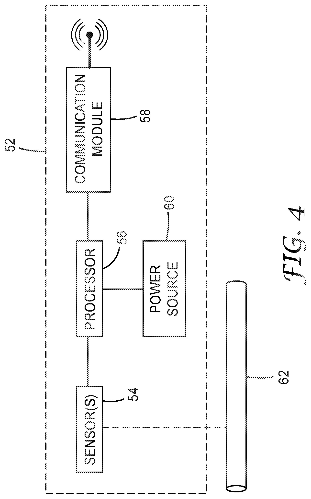
[0008] FIG. 4 is a block diagram of an exemplary communication node.
DETAILED DESCRIPTION
[0009] Embodiments of this invention include a robust network for wireless sensor communication architecture in an enclosure where each sensor may not be able to communicate directly to a communication gateway. Instead, the communication can be directed ad-hoc to a visible (line of sight) node, which in turn can be connected to another node or the end node. In this way, obstructions such as walls, wires, and conduits will not prevent the sensor data transmission to the ultimate end destination such as the communication gateway. This modular and expandable communication architecture can be adapted to high voltage, medium voltage, and low voltage conduits without requiring significant modification to the infrastructure.
[0010] FIG. 1 is a block diagram of the wireless communication system. The system is contained within an enclosure 10 having an access point such as a manhole cover 12. Examples of such enclosures include underground utility vaults and above ground (or grade level) utility cabinets. In some cases, the enclosure can include both an above ground utility cabinet over an underground utility vault. The system includes several communication nodes 16 associated with electrical power lines 18 and wirelessly communicating with a communication gateway 14 via wirelessly transmitting and receiving information. Communication gateway 14 can wirelessly transmit the received sensor data and other information to a remote location such as a utility company. An example of a communication gateway for an underground enclosure is disclosed in PCT Patent Application Publication No. WO 2015/195861, which is incorporated herein by reference as if fully set forth.
[0011] FIG. 2 is a diagram illustrating an exemplary communication node 20 for the system and attached to a power line 28. Communication node 20 may correspond with communication nodes 16. Communication node 20 is physically coupled to a power line 28 via straps 26 and 27, or other fasteners, and can include sensors for monitoring power line 28. For example, communication node 20 includes current measurement coils 22 and 23 for monitoring a current in power line 28 and a temperature measurement sensor 24 attached to power line 28. Communication node 20 also includes a communication module for wirelessly transmitting and receiving information. Communication node 20 can also include indicator lights 21 to indicate a status of the sensors or other components within communication node 20.
[0012] FIG. 3 is a block diagram illustrating communication paths among communication nodes in the system. In this example, various communication nodes are located within an enclosure 30 having manhole cover 12 and communication gateway 14. Communication nodes 32, 40, and 36 have communication paths 42, 50, and 46, respectively, to wirelessly transmit information directly to communication gateway 14, meaning within a line of sight from the communication nodes to the communication gateway. Other direct communication can include within a line of sight from one communication node to another communication node. The line of sight means the center of antenna to antenna from one device to another.
[0013] Communication nodes 34 and 38 have obstructions between them and communication gateway 14. The obstructions mean that the nodes are not within a line of sight of the gateway. Therefore, communication node 34 has a communication path 44 to communication node 36 which can wirelessly receive information from communication node 34 and transmit the information to communication gateway 14. Likewise, communication node 38 has a communication path 48 to communication node 40 which can wirelessly receive information from communication node 38 and transmit such information to communication gateway 14. This example thus illustrates "hopping" communication where certain communication nodes have obstructions between them and communication gateway 14, and information can be transmitted from node-to-node to reach the communication gateway or other ultimate destination.
[0014] FIG. 4 is a block diagram of an exemplary communication node, which may correspond with communication nodes 16. The communication node includes a processor electrically coupled with one or more sensors 54, a communication module 58, and a power source 60. The components 54, 56, 58, and 60, or some of them, can be contained within a housing 52 providing protection from the environment. Housing 52 can be implemented with a metal or plastic weather-proof box, for example. The one or more sensors 54 can be implemented with sensors for detecting electrical data such voltage or current within a power line 62, for measuring emissions (gas/particulate emissions, such as outgassing or smoke), and for measuring environmental conditions around power line 62, or within the vicinity of the communication node, such as temperature, humidity, and sound. In some cases, the sensors only monitor electrical data such voltage or current of a line conductor. In some cases, the sensors can also monitor emissions from the cable or equipment (e.g., electromagnetic, acoustic or other emissions), vibration sensing, or water and/or salinity levels. Furthermore, a communication node can optionally not include a sensor (or not use a sensor) and, instead, be used as a repeater to forward data between communication nodes or from another node to the gateway.
[0015] Power source 60 can be implemented with a portable power source such as a battery or with a circuit for harvesting power from power line 62. In addition, an energy storage device or device with similar capability can be integrated in the system. Communication module 58 can be implemented with a module or circuitry for wireless short range communication, and examples of such communication include the following: the WI-FI technology (Wi-Fi Alliance); the BLUETOOTH technology (Bluetooth SIG, Inc.); and the ZIGBEE wireless language (ZigBee Alliance).
[0016] Examples of a current sensor and a power harvesting circuit are disclosed in, respectively, US Patent Application Publication Nos. 2016/0223592 and 2016/0276954, both of which are incorporated herein by reference as if fully set forth. An example of a holder for a current sensor is disclosed in U.S. patent application Ser. No. 15/188,290, entitled "Holder with Self-Aligning Feature for Holding Current Sensor Around Line Conductor," and filed Jun. 21, 2016, which is incorporated herein by reference as if fully set forth.
[0017] As illustrated in FIGS. 3 and 4, the communication nodes wirelessly transmit and receive information to the communication gateway and to other communication nodes. When information is transmitted from one communication node to another, the information is aggregated for subsequent transmission. The information wirelessly transmitted among the communication nodes, and ultimately to the communication gateway, can include the following: an identification of the communication node from which the information originated; a date, time, and location stamp corresponding to when the information was collected or generated along with the geographic location of the same communication node; sensor data from the same communication node such as the environmental conditions identified above, electrical data, or both environmental conditions and electrical data; and thresholds for the same communication node. Table 1 is an exemplary data structure for such information transmitted among the communication nodes, including information aggregated from multiple communication nodes.
TABLE-US-00001 TABLE 1 Node Information Current Communication Node Data from the Communication Node Node ID Date, time, and location stamp Node Sensors Sensor data 1, 2, . . . n Node Thresholds Thresholds 1, 2, . . . n Aggregated Communication Data Nodes Node 1 ID Date, time, and location stamp for node 1 Node 1 Sensors Sensor data 1, 2, . . . n for node 1 Node 1 Thresholds Thresholds 1, 2, . . . n for node 1 Node 2 ID Date, time, and location stamp for node 2 Node 2 Sensors Sensor data 1, 2, . . . n for node 2 Node 2 Thresholds Thresholds 1, 2, . . . n for node 2 . . . Node N ID Date, time, and location stamp for node N Node N Sensors Sensor data 1, 2, . . . n for node N Node N Thresholds Thresholds 1, 2, . . . n for node N
[0018] The thresholds can be used by the communication nodes to determine, for example, when to wirelessly transmit the information generated by the communication nodes, possibly including aggregated information from multiple communication nodes. Various conditions based upon the thresholds can be established such that the processors in the communication nodes are configured to transmit the information based upon such conditions.
[0019] These conditions can be established for thresholds of a particular communication node. For instance, a communication node 1 can have a condition 1 as follows: if any of the thresholds 1, 2, . . . n for Node 1 are satisfied, transmit sensor data to the next node. For example, if the temperature for the power line monitored by communication node 1 exceeds a particular threshold temperature, communication node 1 will then wirelessly transmit information including the temperature data from the corresponding sensor associated with communication node 1. As another example, communication node 1 can have another condition 2 as follows: if at least two of the thresholds 1, 2, . . . n for Node 1 are satisfied, transmit sensor data to the next node. For example, if the temperature and current for the power line monitored by communication node 1 exceeds both a particular threshold temperature and a particular current value, communication node 1 will then wirelessly transmit information including the temperature and current data from the corresponding sensor associated with communication node 1.
[0020] These conditions can also be established for thresholds of a particular communication node and aggregated sensor data transmitted by the particular communication node. The aggregated data includes the data from communication nodes having a communication path and transmitting information to the particular communication node. For instance, a communication node N can have a condition 1 as follows: if any of the thresholds 1, 2, . . . n for the aggregated nodes are satisfied, transmit aggregated sensor data to the next node. As another example, a communication node N can have a condition 2 as follows: if at least two of the thresholds 1, 2, . . . n for the aggregated nodes are satisfied, transmit aggregated sensor data to the next node.
[0021] The conditions provided above are exemplary, and other conditions based upon various thresholds or other information can also be established. Table 2 is an exemplary data structure for the conditions, which can be stored in the communication nodes, or otherwise accessed by the communication nodes, for determining when to wirelessly transmit information.
TABLE-US-00002 TABLE 2 Communication Node Conditions Communication Node ID Conditions for Transmission Node 1 Conditions 1, 2, . . . n for Node 1 Node 2 Conditions 1, 2, . . . n for Node 2 . . . Node N Conditions 1, 2, . . . n for Node N
* * * * *
D00000
D00001
D00002
D00003
D00004
XML
uspto.report is an independent third-party trademark research tool that is not affiliated, endorsed, or sponsored by the United States Patent and Trademark Office (USPTO) or any other governmental organization. The information provided by uspto.report is based on publicly available data at the time of writing and is intended for informational purposes only.
While we strive to provide accurate and up-to-date information, we do not guarantee the accuracy, completeness, reliability, or suitability of the information displayed on this site. The use of this site is at your own risk. Any reliance you place on such information is therefore strictly at your own risk.
All official trademark data, including owner information, should be verified by visiting the official USPTO website at www.uspto.gov. This site is not intended to replace professional legal advice and should not be used as a substitute for consulting with a legal professional who is knowledgeable about trademark law.