Apparatus For Use With Hydrogen Radicals And Method Of Using Same
Lin; Xing ; et al.
U.S. patent application number 15/974948 was filed with the patent office on 2019-11-14 for apparatus for use with hydrogen radicals and method of using same. The applicant listed for this patent is ASM IP Holding B.V.. Invention is credited to Peipei Gao, Bubesh Babu Jotheeswaran, Xing Lin, Fei Wang, Wentao Wang, Chuang Wei.
| Application Number | 20190348261 15/974948 |
| Document ID | / |
| Family ID | 68465250 |
| Filed Date | 2019-11-14 |


View All Diagrams
| United States Patent Application | 20190348261 |
| Kind Code | A1 |
| Lin; Xing ; et al. | November 14, 2019 |
APPARATUS FOR USE WITH HYDROGEN RADICALS AND METHOD OF USING SAME
Abstract
A system and method suitable for removing both carbon-based contaminants and oxygen-based contaminants from a substrate within a single process chamber are disclosed.
| Inventors: | Lin; Xing; (Chandler, AZ) ; Wei; Chuang; (Chandler, AZ) ; Wang; Wentao; (Phoenix, AZ) ; Gao; Peipei; (Tempe, AZ) ; Wang; Fei; (Tempe, AZ) ; Jotheeswaran; Bubesh Babu; (Gilbert, AZ) | ||||||||||
| Applicant: |
|
||||||||||
|---|---|---|---|---|---|---|---|---|---|---|---|
| Family ID: | 68465250 | ||||||||||
| Appl. No.: | 15/974948 | ||||||||||
| Filed: | May 9, 2018 |
| Current U.S. Class: | 1/1 |
| Current CPC Class: | H01J 37/32495 20130101; C23C 16/45544 20130101; B08B 17/06 20130101; C23C 16/45555 20130101; C23C 16/4404 20130101; C23C 16/45565 20130101; H01L 21/67017 20130101; H01L 21/02057 20130101; H01J 2237/335 20130101; B08B 5/00 20130101; C23C 16/403 20130101; H01L 21/3003 20130101; H01L 21/6719 20130101; H01J 37/3244 20130101 |
| International Class: | H01J 37/32 20060101 H01J037/32; H01L 21/67 20060101 H01L021/67; B08B 17/06 20060101 B08B017/06; B08B 5/00 20060101 B08B005/00 |
Claims
1. A reactor system comprising: a reaction chamber comprising an interior surface; a remote plasma source coupled to the reaction chamber; and a hydrogen source coupled to the remote plasma source, wherein at least a portion of the interior surface comprises a metal oxide coating.
2. The reactor system of claim 1, wherein the metal oxide comprises aluminum oxide.
3. The reactor system of claim 1, wherein the coating is formed using atomic layer deposition.
4. The reactor system of claim 1, wherein a thickness of the coating ranges from about 100 nm to about 750 nm.
5. The reactor system of claim 1, wherein the coating is formed using an anodized process and wherein the coating is non-porous.
6. The reactor system of claim 5, wherein an average surface roughness of the coating ranges from about 0.1 .mu.m to about 0.8 .mu.m.
7. The reactor system of claim 5, wherein a thickness of the coating ranges from about 100 nm to about 1000 nm.
8. A gas distribution apparatus comprising: a top section; a bottom section having a plurality of holes formed there through; and a manifold plate there between, wherein the manifold plate comprises a plurality of gas channels radially extending from a center region of the manifold plate.
9. The gas distribution apparatus of claim 8, wherein the manifold plate comprises about 4 to about 48 gas channels.
10. The gas distribution apparatus of claim 8, wherein a gas comprising hydrogen radicals is received through a portion of the top section and is distributed to an area between the top section and the holes using the plurality of gas channels.
11. The gas distribution apparatus of claim 8, wherein a diameter of each of the holes ranges from about 0.5 mm to about 3 mm.
12. The gas distribution apparatus of claim 8, wherein a diameter of each of the channels ranges from about 5 mm to about 15 mm.
13. The gas distribution apparatus of claim 8, wherein the manifold plate comprises metal and an interior surface coated with a metal oxide.
14. The gas distribution apparatus of claim 8, wherein the manifold plate is coupled to the top plate using one or more of fasteners and welding.
15. A gas distribution apparatus comprising: a top section having an opening to receive a gas; a bottom section having a plurality of holes formed there through, the bottom section comprising a center region and an outer region; and a chamber formed between the top section and the bottom section, wherein a diameter of the holes in the outer region is greater than a diameter of the holes in the center region.
16. The gas distribution apparatus of claim 15, wherein a diameter of the holes in the center region ranges from about 0.5 mm to about 1.5 mm.
17. The gas distribution apparatus of claim 15, wherein a diameter of the holes in the outer region ranges from about 1 mm to about 3 mm.
18. The gas distribution apparatus of claim 15, wherein an interior of the surface is coated with a metal oxide.
19. The gas distribution apparatus of claim 15, wherein a density of the plurality of holes is greater at the outer region than the density at the center region.
20. The gas distribution apparatus of claim 19, wherein a perimeter of the outer region is greater than a perimeter of a substrate to be processed in a reaction chamber comprising the gas distribution system.
Description
FIELD OF INVENTION
[0001] The present disclosure generally relates to an apparatus and a method for manufacturing electronic devices. More particularly, the disclosure relates apparatus that use hydrogen radicals, to components thereof, and to methods of forming and using the same.
BACKGROUND OF THE DISCLOSURE
[0002] During the fabrication of electronic devices, such as semiconductor devices, it is often desirable to remove contaminants from a surface of a substrate prior to a film deposition process. If not removed, contaminants on the surface can adversely affect mechanical and/or electrical properties of the devices formed using the substrates.
[0003] By way of examples, some device manufacturing processes can include selective deposition of a film on portions of a substrate surface, wherein the film selectively forms on a portion (e.g., a first material) relative to another portion (e.g., a second material) on the substrate surface. In such cases, it may be particularly desirable to remove oxygen-based contaminants (e.g., oxides, such as metal and non-metal oxides) and carbon-based contaminants, such as carbonaceous contaminants and hydrocarbon contaminants from the substrate surface.
[0004] Typical approaches to contaminant removal focus on removing one of the contaminants, either carbon-based or oxygen-based, but not both. This may be in part due to equipment limitations of the prior approaches. For example, a typical process can include using a hydrofluoric acid wet process to remove the oxygen-based contaminants. Alternatively, fluorine radicals, formed from activating a fluorine-containing gas, can be used to remove the oxygen-based material. Unfortunately, fluorine radicals are generally very corrosive to reactor components that may be desirable for carbon removal, such as quartz; the corrosion can lead to degradation of the reaction chamber and to reactor components, which can also lead to particle generation.
[0005] Activated hydrogen gas, which includes hydrogen radicals, can be used to remove carbon from a substrate surface. In these cases, quartz may be a preferred reactor component material to mitigate hydrogen radical recombination. However, quartz exhibits relatively poor heat transfer characteristics, leading to poor temperature uniformity across a substrate surface. Furthermore, in the case of showerhead reactor designs, hydrogen radicals generally enter a showerhead at a center region of the showerhead and then transport horizontally to an edge of the showerhead, where radicals often recombine. As a result, the substrate center may be exposed to a higher density of hydrogen radicals, compared to an outer periphery of the substrate, leading to substrate center-to-edge removal non-uniformity. Accordingly, systems and methods to remove both carbon-based and oxygen-based contaminants are desired. Additionally or alternatively, improved methods and apparatus to provide a relatively uniform distribution of hydrogen radicals to a substrate surface--e.g., during a process to remove carbon-based contamination--are desired.
SUMMARY OF THE DISCLOSURE
[0006] Various embodiments of the present disclosure provide improved methods, apparatus, and systems for providing reactive species, such as activated hydrogen species (e.g., hydrogen radicals) and/or other activated species (e.g., derived from one or more halogen-containing gases) to a surface of a substrate. Exemplary methods and systems can be used to remove carbon-containing material (e.g., contaminants) and/or oxygen-containing material (e.g., contaminants) from a surface of a substrate. While the ways in which the various drawbacks of the prior art are discussed in greater detail below, in general, the methods and systems described herein can relatively uniformly distribute hydrogen radicals across a surface of a substrate. Additionally or alternatively exemplary methods and systems can be used to remove both carbon-containing and oxygen-containing contaminants from a surface of a substrate.
[0007] In accordance with at least one exemplary embodiments of the disclosure, a reactor system includes a reaction chamber including an interior surface, a remote plasma source coupled to the reaction chamber, and a hydrogen source coupled to the remote plasma source, wherein at least a portion of the interior surface comprises a coating, such as a metal oxide coating. The coating can be relatively non-porous and/or smooth to mitigate recombination of active species, such as hydrogen radicals. Atomic layer deposition or an anodized process can be used to form the non-porous coating.
[0008] In accordance with at least another exemplary embodiment of the disclosure, a gas distribution apparatus includes a top section (e.g., a top plate), a bottom section (e.g., a bottom plate) having a plurality of holes formed there through, and a manifold plate there between. The manifold plate can include a plurality of gas channels radially extending from a center region of the manifold plate to a periphery of the manifold plate to facilitate provision of a more uniform distribution of activated species (e.g., hydrogen radicals) within the gas distribution apparatus and consequently to a surface of a substrate. An interior of the top section, bottom section, and/or manifold plate can be coated with a coating--e.g., a metal oxide--as described herein. The coating can further facilitate a longer lifespan of the hydrogen radicals, thereby further increasing uniformity of the distribution of the radicals and of the substrate processing.
[0009] In accordance with at least one other embodiment of the disclosure, a gas distribution apparatus includes a top section (e.g., a top plate) having an opening to receive a gas, a bottom section (e.g., a bottom plate) having a plurality of holes formed there through, the bottom section comprising a center region and an outer region, and a chamber formed between the top section and the bottom section. To facilitate desired distribution of active species to a substrate surface, the bottom section can include one or more of: a diameter of the holes in the outer region is greater than a diameter of the holes in the center region, a density (per unit surface area of a bottom surface of the bottom section) of the holes in the outer region is greater than a density of the holes in the center region, and a perimeter of the outer region is greater than a perimeter of a substrate to be processed in a reaction chamber comprising the gas distribution system.
[0010] For purposes of summarizing aspects of the invention and the advantages achieved over the related art, certain objects and advantages of the invention are described in this disclosure. Of course, it is to be understood that not necessarily all such objects or advantages may be achieved in accordance with any particular embodiment of the invention. Thus, for example, those skilled in the art will recognize that the invention may be embodied or carried out in a manner that achieves or optimizes one advantage or group of advantages as taught herein without necessarily achieving other objects or advantages as may be taught or suggested herein.
BRIEF DESCRIPTION OF THE DRAWING FIGURES
[0011] A more complete understanding of the embodiments of the present disclosure may be derived by referring to the detailed description and claims when considered in connection with the following illustrative figures.
[0012] FIGS. 1 and 2 illustrate concentration profiles of hydrogen radicals in a typical gas distribution apparatus.
[0013] FIG. 3 illustrates a cross-sectional view of a reactor system in accordance with at least one embodiment of the disclosure.
[0014] FIG. 4 illustrates a cross-sectional view of another reactor system in accordance with at least one embodiment of the disclosure.
[0015] FIGS. 5A and 5B illustrate views of a reactor system including a showerhead exhaust in accordance with at least one embodiment of the disclosure.
[0016] FIGS. 6A, 6B and 6C illustrate exemplary reactor component coatings.
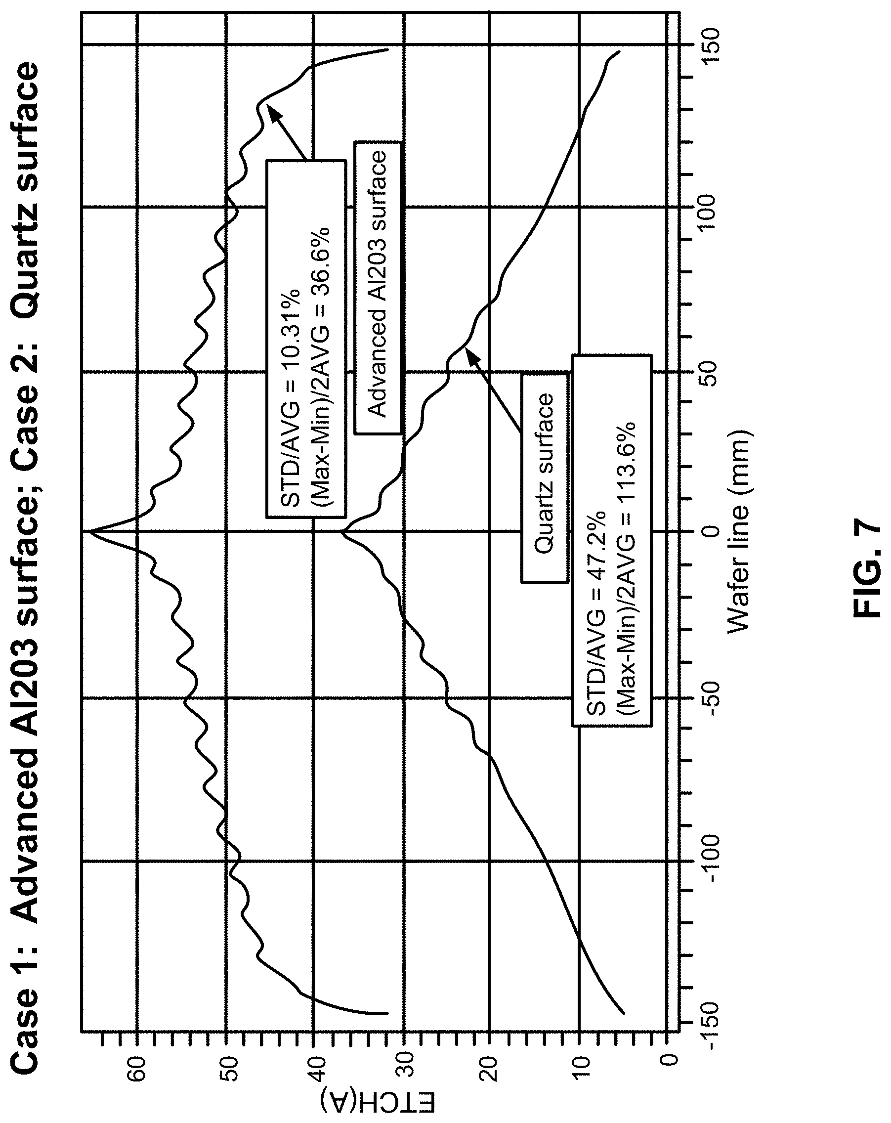
[0017] FIG. 7 illustrates hydrogen radical distribution in a quartz gas distribution apparatus and in a gas distribution apparatus having a coating in accordance with at least one exemplary embodiment of the disclosure.
[0018] FIG. 8 illustrates a portion of a gas distribution apparatus including a coating in accordance with at least one embodiment of the disclosure.
[0019] FIG. 9 illustrates a gas distribution apparatus including a manifold plate in accordance with at least one embodiment of the disclosure.
[0020] FIG. 10 illustrates a portion of a gas distribution apparatus including a manifold plate in accordance with at least one embodiment of the disclosure.
[0021] FIG. 11 illustrates a fastener for use in a gas distribution apparatus including a manifold plate in accordance with at least one embodiment of the disclosure.
[0022] FIGS. 12A, 12B and 12C illustrate weld joints and a dowel in a gas distribution apparatus including a manifold plate in accordance with at least one embodiment of the disclosure.
[0023] FIG. 13 illustrates a bottom surface of a bottom section of a gas distribution apparatus including a manifold plate in accordance with at least one embodiment of the disclosure.
[0024] FIGS. 14A, 14B, 14C, 15A and 15B illustrate exemplary gas distribution apparatus in accordance with embodiments of the disclosure.
[0025] It will be appreciated that elements in the figures are illustrated for simplicity and clarity and have not necessarily been drawn to scale. For example, the dimensions of some of the elements in the figures may be exaggerated relative to other elements to help to improve understanding of illustrated embodiments of the present disclosure.
DETAILED DESCRIPTION OF EXEMPLARY EMBODIMENTS
[0026] The description of exemplary embodiments of methods, systems, and apparatus provided below is merely exemplary and is intended for purposes of illustration only; the following description is not intended to limit the scope of the disclosure or the claims. Moreover, recitation of multiple embodiments having stated features is not intended to exclude other embodiments having additional features or other embodiments incorporating different combinations of the stated features.
[0027] As set forth in more detail below, exemplary methods, apparatus, and systems described herein can be used in the manufacture of electronic devices, such as semiconductor devices. In particular, exemplary systems can be used to provide activated species (e.g., derived from hydrogen and/or halogen gas) to a surface of a substrate to, e.g., clean or remove contaminants from the substrate surface. In this disclosure, "gas" may include vaporized solid and/or liquid and may be constituted by a single gas or a mixture of gases, depending on the context. Exemplary methods, apparatus, and systems can provide extended lifetimes to activated species (e.g., hydrogen radicals and/or activated halogen species) within a reactor and/or a gas distribution apparatus of a reactor and/or can provide more uniform distribution of the activated species.
[0028] The methods, apparatus, and systems can use or include a reactor system with a single process chamber, having a capability to remove, for example, carbon-based contaminants (also referred to herein as carbon-based materials) and/or oxygen-based contaminants (also referred to herein as oxygen-based materials). By way of examples, the methods, apparatus, and systems can be used to clean semiconductor substrates comprising at least one of the following materials: silicon; silicon germanium; or germanium, for example. In one embodiment, the percentage of germanium in silicon germanium may vary from 10% to 90%. Also, embodiments of the disclosure may be used to etch carbon layers, such as an advanced patterning film (APF); photoresists; or other carbon contaminations including CHFx, SiOF, SiC, or SiOC. In addition, embodiments of the disclosure may be used to clean a surface of dielectric materials, such as silicon oxide, silicon nitride, silicon oxynitride, silicon carboxide, and silicon carboxynitride. Furthermore, embodiments of the disclosure may be applied to patterned substrate surfaces. Exemplary methods can also be used to remove metal from metal carbides, such as TiAlC or TaAlC and the like.
[0029] Activated hydrogen--e.g., hydrogen radicals generated by a remote plasma can be used to remove the carbon-based materials in gas-phase reactors. However, as illustrated in FIG. 1, where darker regions indicate a higher concentration of hydrogen radicals, the hydrogen radicals can often recombine to form hydrogen gas before exiting a gas distribution apparatus or reaching a substrate surface. In the illustrated example, the hydrogen radicals are depleted as the gas containing the radicals moves downward through the gas distribution apparatus and are further depleted once the gas begins to travel radially outward at the bottom of the gas distribution apparatus. This is thought to be due to the high diffusion rates of hydrogen, which allows the hydrogen to quickly reach and react with surfaces, where recombination events occur. FIG. 2 illustrates a typical distribution of hydrogen radicals across a surface of a substrate, where the hydrogen radicals are deleted near a periphery of the substrate relative to the center of the substrate.
[0030] FIG. 3 illustrates a reactor system 300 in accordance with at least one embodiment of the disclosure. System 300 includes a reaction chamber 310, a susceptor 320, a showerhead 330, a remote plasma unit 340, and a transport path 345 between the remote plasma unit 340 and the reaction chamber 310. A substrate 350 is placed on the susceptor 320 for processing.
[0031] Reaction chamber 310, at least in part, defines a space in which the substrate 350 is processed. To increase a lifetime of hydrogen radicals produced in remote plasma unit 340, reaction chamber 310 or a portion thereof, susceptor 320, showerhead 330, and/or transport path 345 can coated with materials (e.g., illustrated as coating 355) and/or be formed of bulk ceramic material in order to both promote hydrogen radical lifetime and allow for compatibility with other activated species, such as activated species (e.g., including radicals) derived from one or more halogen-containing gasses. The materials for coating 355 can include a metal oxide comprising at least one of: anodized aluminum oxide (Al.sub.2O.sub.3); atomic layer deposition (ALD)-formed aluminum oxide; plasma sprayed Al.sub.2O.sub.3; bare aluminum parts with native aluminum oxide, yttrium oxide (Y.sub.2O.sub.3); yttrium oxide stabilized zirconium oxide (YSZ); zirconium oxide (ZrO); lanthanum zirconium oxide (LZO); yttrium aluminum garnet (YAG); yttrium oxyfluoride (YOF); combination of the above materials; or the above substrate doped with other glass phase materials. In some cases, the coating materials can be made with two layers. For example, the first layer may be coated with anodized Al.sub.2O.sub.3 and the second layer may be coated with ALD-formed Al.sub.2O.sub.3. The coating may be amorphous phase, crystalline phase, or mixed. The bulk ceramic material may include: aluminum oxide (Al.sub.2O.sub.3); zirconium oxide (ZrO.sub.2); yttrium oxide (Y.sub.2O.sub.3); or yttrium oxide stabilized zirconium oxide (YSZ). In accordance with particular exemplary embodiments, of the disclosure, the coating includes a material, such as oxide materials (e.g., metal oxides) that have lower recombination coefficients compared to, for example metals, and thus can be used to facilitate longer lifetimes of hydrogen radicals in reactor system 300. The metals oxides noted above, such as, Al.sub.2O.sub.3 and Y.sub.2O.sub.3, also exhibit good resistivity to corrosion in the presence of activated halogen (e.g., fluorine-containing) gases. These ceramic materials, particularly Al.sub.2O.sub.3, are relatively inexpensive, and can be coated on large machining parts with different manufacturing methods. The inventors found that smooth (e.g., having a mean or average roughness (Ra) of about 0.1-0.8 .mu.m, which can be the same as or similar to the Ra of substrate 350), non-porous (e.g., <1% porosity) metal oxide coatings work well to extend hydrogen radical lifetimes within a reactor system. One way to achieve the smooth, non-porous coating is to deposit the coating material using atomic layer deposition. In this case, a thickness of the coating can range from about 100 nm to about 750 nm or about 250 nm to about 500 nm. A second approach to obtain a smooth, non-porous coating is to form a non-porous anodize (e.g., Al.sub.2O.sub.3) coating having a thickness of about 100 nm to about 1000, about 100 nm to about 750 nm or about 250 nm to about 500 nm.
[0032] FIGS. 6A, 6B and 6C illustrate transmission electron microscopy images of: FIG. 6A: a traditional anodized (Al.sub.2O.sub.3) coating, FIG. 6B: a non-porous ALD coating, and FIG. 6C: a non-porous anodized coating. As illustrated in FIG. 6A, coatings formed using a traditional anodization process exhibit hexogen hole patterns, which can trap hydrogen radicals, which can, in turn, lead to relatively short hydrogen radical lifetimes. In contrast, non-porous Al.sub.2O.sub.3 coatings exhibit a relatively smooth and non-porous surface, resulting in relatively low hydrogen radical surface recombination and even better performance than typical quartz materials. FIG. 7 illustrates a comparison of carbon removal rates on a surface of a substrate between a reactor system including Al.sub.2O.sub.3 coated surface and a reactor system including quartz surface.
[0033] An Exemplary ALD process suitable for coatings as described herein can be run at, for example, about 1 to about 10 Torr at about 150.degree. C. to about 400.degree. C.
[0034] Generally, the non-porous anodized process can be used to deposit relatively thin (e.g., films having a thickness less than one micron, as compared to traditional anodized processes that deposit films up to 100 microns). Further, generally more factors, such as applied voltage, electrolyte composition, surface pretreatment, and the like, can be used to optimize films formed using the non-porous anodized process, compared to typical anodized process.
[0035] The ALD and non-porous methods described above can be conformal, such that a coating 804 (illustrated in FIG. 8) covers various reactor system 100 part uniformly, even across small feature, like holes 802 formed within a bottom section 800 of a gas distribution apparatus, described in more detail below. In the illustrated example, D1 can range from about 0.5 mm to about 4 mm; D2 can range from about 0.5 mm to about 8 mm; and D3 can range from about 0.5 mm to about 8 mm. Traditional techniques, such as plasma or thermal spray Al.sub.2O.sub.3 coating techniques generally cannot uniformly cover such features within a reactor system. Any area not suitably covered with the coating can be susceptible to corrosion, which can lead to particle and defects on the substrate surface.
[0036] With reference again to FIG. 6, both ALD and non-porous anodize Al.sub.2O.sub.3 coatings are relatively dense (e.g., >3.1 g/cm.sup.3), and can withstand aggressive (e.g., F-containing) plasma. Extremely harsh ICP plasma corrosion tests demonstrate that corrosion resistance of non-porous Al.sub.2O.sub.3 coatings is comparable to bulk Al.sub.2O.sub.3 materials. For these materials, the reactive F ions and/or radicals only penetrate a few nm into the coating surface, and form an AlF.sub.x passivation layer. With typical carbon and/or oxide residue removal processes, a surface of the coating was not damaged with reactive fluorine radicals. Further, because coating 355 is relatively thin (e.g., about 100 nm to about 1000 nm), the coating is relatively resistant to cracking, even at elevated temperatures of up to about 500.degree. C. This is beneficial for some processes requiring high temperature. For example, in carbon material removal for a SiGe pre-clean process, an effective cleaning generally involves a relatively high temperature (e.g., about 150.degree. C. to about 300.degree. C.), and so coatings that do not crack or peel when exposed to such temperatures are desirable.
[0037] Referring again to FIG. 3, in the illustrated example, reactor system 300 includes a first gas source 360, a second gas source 370, a third gas source 380, and a fourth gas source 390, which all may provide gas to the remote plasma unit 340. One or more of first gas source 360, second gas source 370, third gas source 380, and fourth gas source 390 may additionally or alternatively be configured to provide gas directly into reaction chamber 310, without going through remote plasma unit 340. Although illustrated with four gas sources, reactor system 100 can include any suitable number of gas sources, and need not include all four gas sources.
[0038] First gas source 360 may comprise a source of a precursor gas that produces activated halogen species--e.g., fluorine radicals, such as NF.sub.3, CF.sub.4, C.sub.2F.sub.6, C.sub.4F.sub.6, C.sub.4F.sub.8, COF.sub.2, SF.sub.6, or WF.sub.6, for example. Second gas source 370 may comprise a source of a gas that produces hydrogen radicals, such as H.sub.2, NH.sub.3, and/or H.sub.2O, for example. Additionally or alternatively, second gas source 370 may comprise a gas that produces oxygen radicals, such as oxygen or ozone, for example. Third gas source 380 may be a source of NH.sub.3. Fourth gas source 190 may be a source of an inert gas, such as argon, helium, or neon, for example.
[0039] Remote plasma unit 340 generates activate species (e.g., radicals) from one or more source gases (e.g., one or more gases from first gas source 360, second gas source 370, third gas source 380, and/or fourth gas source 390). The generated radicals then enter the reaction chamber 110 through gas distribution apparatus (e.g., showerhead) 330 and then flow onto substrate 350. The remote plasma source may include: a toroidal style ICP source or a coil style ICP source driven by different RF frequencies, such as a 400 kHz, 2 MHz, 60 MHz and 2.56 GHz microwave source. By way of particular example, remote plasma unit 340 can be or comprise a Paragon H* remote plasma unit from MKS Instruments.
[0040] FIG. 4 illustrates another reactor system 400 in accordance with at least one embodiment of the disclosure. Reactor system 400 can be similar to reactor system 300 and includes a reaction chamber 410, a susceptor 420, a gas distribution apparatus (e.g., showerhead) 430, a first remote plasma unit 440, a second remote plasma unit 445, a transport path 446 below first remote plasma unit 440, and a second transport path 447 below second remote plasma unit 445. A substrate 450 is placed on susceptor 420 for processing. Reactor system 400 may also include a first gate vale 448 and/or a second gate valve 449.
[0041] Reaction chamber 410, at least in part, defines a space in which substrate 450 is processed. Reaction chamber 410, susceptor 420, and/or showerhead 430 can be coated with materials (e.g., coating 495) and/or comprise materials facilitate extension of hydrogen radical lifetime and/or that allow for compatibility with different radicals, such as any of the coating and materials described above, and can be formed using any of the techniques described above.
[0042] In the illustrated example, reactor system 400 includes a first gas source 460, a second gas source 470, a third gas source 480, and a fourth gas source 490, which may provide gas to the first remote plasma unit 440, second remote plasma unit 445, and/or directly to reaction chamber 410. First gas source 460, second gas source 470, third gas source 480, and/or fourth gas source 490 can be the same or similar to corresponding gas sources discussed above in connection with FIG. 3. First remote plasma unit 440 and second remote plasma unit 445 may comprise or be a toroidal style ICP source or a coil style ICP source driven by different RF frequencies, such as a 400 kHz, 2 MHz, 60 MHz and 2.56 GHz microwave source, for example. And, at least one of first remote plasma unit 440 and second remote plasma unit 445 can be or include a Paragon H* remote plasma unit from MKS Instruments.
[0043] In accordance with illustrative examples, first remote plasma unit 440 can be used to form activated species of a first type (e.g., comprising fluorine radicals) and second remote plasma unit 445 can be used to form activated species of a second type (e.g., hydrogen radicals) from the gas sources. The generated radicals can then enter reaction chamber 410 through gas distribution apparatus (e.g., a showerhead) 430 and then flow onto the substrate 450. To prevent radicals generated by one remote plasma unit back streaming into the second remote plasma, gate valves 448 and 449 may be located at or near an outlet of the respective remote plasma unit.
[0044] FIGS. 5A and 5B illustrate another reactor system 500 in accordance with at least one exemplary embodiment of the disclosure. Reactor system 500 can include the same or similar components as described above in connection with reactor systems 300 and 400, including the same or similar coatings, gas sources and/or remote plasma units.
[0045] Reactor system 500 includes a reaction chamber 502, a gas distribution apparatus (e.g., a showerhead) 504, and a showerhead exhaust 506. Active species with inert carrier gas can be transported through a conduit 508 into a plenum 507, where only a fraction of gas mixture will be dispensed through the showerhead 504 gas holes, while the rest will be dispensed into showerhead exhaust 506 and ultimately into vacuum pump. The fraction of the mixture that goes into showerhead exhaust 506 will be regulated by a PCV valve for process tuning and optimization. An advantage for this approach is that H* radical concentration inside plenum will be much more uniform due to H* transport time reduction between the center and the edge, which ultimately reduce the carbon removal non uniformity. Also this will keep the oxide removal non uniformity unchanged, if not improved, because active species concentration before showerhead 504 will not decrease. Similar to reactor systems 300 and 400, active species from one or more remote plasma units can be received with conduit (transport path) 508. Any of the wetted surface of reactor system 500 can be coated with and/or be formed of any of the materials described above in connection with reactor systems 300 and 400 and can be formed using the techniques described above.
[0046] Turing now to FIGS. 9 and 10, an exemplary gas distribution apparatus 900, including a manifold plate 906, is illustrated. Gas distribution apparatus 900 includes a top section 902, a bottom section 904, and manifold plate 906. Gas distribution apparatus 900 can be used in connection with, for example, any of reactor systems 300, 400, 500, and can be used to further facilitate longevity of activated species, such as hydrogen radical within gas distribution system 900 and within the reactor system (e.g., across a substrate surface within a reaction chamber of the reactor system).
[0047] In operation, one or more gases are received at an inlet 914 of top section 902 and are dispersed within a chamber 916 that is formed between top section 902 and bottom section 904. The gas(es) are then distributed to a substrate that resides beneath gas distribution apparatus 900.
[0048] Top section 902 can be or comprise a plate. The plate can be formed of, for example aluminum or one or more of the materials described above. One or more surfaces, e.g., surface 908 of top section 902 can be coated with a material, such as either of coatings 355 or 495.
[0049] Bottom section 904 can also be or comprise a plate. The plate can be formed of, for example aluminum and/or nickel or one or more of the materials described above. One or more surfaces, e.g., surface 910 of bottom section 904 can be coated with a material, such as either of coatings 355 or 495. Bottom section 904 includes a plurality of holes 912 (which can be the same or similar to hole 802) through which gas can travel from chamber 916 to a substrate surface. Holes 912 can be distributed uniformly and/or be of about the same size, or may be in other configurations, as described in more detail below.
[0050] Manifold plate 906 can be used to facilitate a more even distribution of activated species (e.g., hydrogen radicals) from a remote plasma unit, such as any of remote plasma units 340, 440, 445. Manifold plate 906 includes a plurality of gas channels 918, 920 to distribute activated species to a region away from the center of gas distribution apparatus 900. As illustrated, gas channels 918, 920 can be generally perpendicular to a flow of gas from inlet 914 and can extend radially and/or perpendicular to the inlet flow. Each gas channel can extend from about 10 percent to about 100 percent or about 20 percent to about 80 percent, or about 40 percent to about 70 percent of a radius or similar dimension of chamber 916. Each gas distribution channel can 918, 920 have a diameter of about 2 mm to about 20 mm, or about 5 mm to about 15 mm, or about 7 mm to about 12 mm. In general, the diameter (or similar cross-sectional dimension) should be large enough to mitigate hydrogen radial recombination. Manifold plate 906 can include any suitable number of gas channels; for example, manifold plate 906 can include from about 2 to about 50, about 4 to about 48, or about 10 to about 30 channels. In some cases, to compensate for non-uniformity, due to other factors, such as temperature or the like, gas channels 918, 920 may be non-uniformly distributed and/or sized (e.g., the length and/or diameter of the channels may vary).
[0051] FIGS. 11 and 12A-12C illustrate exemplary techniques to couple manifold plate 906 to one or more of top section 902 and bottom section 904. FIG. 11 illustrates use of a fastener 1102 (e.g., a screw or bolt coated with a coating as described above). Fastener 1102 can include a through hole 1104 at or near a bottom center of the fastener to reduce by-product accumulation.
[0052] FIGS. 12A and 12B illustrate weld joints 1202, 1204 that are used to couple manifold plate 906 to top section 902. Weld joints 1202, 1204 can be formed via, for example, e-beam welding techniques. Weld joints 1202, 1204 could be used in addition to or as an alternative to fastener 1102.
[0053] FIG. 12C illustrates a dowel 1206 that can be used to affix manifold plate 906 to top section 902. Dowel 1206 can be formed of, for example, stainless steel.
[0054] Turning now to FIG. 13, a bottom section 1300, suitable for use as bottom section 904, is illustrated. Bottom section 1300 includes a center region 1306, including a plurality of holes 1302, and an outer region 1308, including a plurality of holes 1304. Center region 1306 can include about 10 percent to about 99 percent, about 25 percent to about 75 percent, or about 75 percent to about 99 percent of a bottom surface of bottom section 1300. In accordance with one example, outer region include the outer most ring of holes 1304. The holes can be configured as, for example, concentric rings of holes. In accordance with at least one exemplary embodiment of the disclosure, a diameter of holes 1304 in outer region 1308 ranges from about 1 mm to about 3 mm, about 1.5 to about 2.5 mm, or about 1.8 mm to about 2.2 mm. A diameter of holes 1302 in center region 1306 can range from about 0.5 mm to about 1.5 mm, about 0.75 to about 1.25 mm, or about 0.8 mm to about 1.2 mm.
[0055] FIGS. 14A-14C illustrate an effect of using larger diameter holes at an out edge of bottom section 1300. In FIG. 14A, all of the holes are of the same diameter (1 mm). In this case, the distribution of hydrogen radials is less than uniform, with a higher concentration of hydrogen radicals in center region 1306 relative to outer region 1308. In FIG. 14B, the diameter of holes in outer region 1308 is increased to 1.5 mm, and the uniformity of distribution of hydrogen radicals is improved. In FIG. 14C, the diameter of the holes in outer region 1308 is increased to 2 mm, and the uniformity of distribution of hydrogen radicals is further improved. Further, the placement and/or diameter of holes in outer region 1308 can be tuned to exhibit an edge tilt profile (as illustrated in FIG. 14C), rather than an edge roll off profile (as illustrated in FIG. 14A).
[0056] In accordance with further exemplary embodiments of the disclosure, bottom section 1300 can, in addition to or in lieu of having holes of different sizes, have various hole densities in regions extending radially from a center of bottom section 1300. For example, a density of holes can increase (e.g., linearly, geometrically, or the like) from a center of bottom section 1300 to an outer edge of bottom section 1300. The density of holes can be designed to provide uniform species (e.g., hydrogen radical) distribution.
[0057] In accordance with yet further exemplary embodiments of the disclosure, bottom section 1300 can, in addition to or in lieu of having holes of different sizes and/or densities, have a size that is larger than the size of a substrate being processes. For example, a diameter of similar dimension can be about 1 percent to about 100 percent, about 2 percent to about 50 percent, or about 5 percent to about 30 percent larger than the diameter (or similar dimension) of the substrate to be processed. Providing a bottom section that is larger than the substrate is thought to further reduce any edge roll off, as illustrated in FIGS. 15A and 15B, where FIG. 15A illustrates a bottom section 1502 that is about the same size as an underlying substrate 1504, and FIG. 15B illustrates a bottom section 1506 that is larger than an underlying substrate 1508. The effects of roll off are reduced by using the apparatus illustrated in FIG. 15B relative to the apparatus illustrated in FIG. 15A.
[0058] Methods in accordance with exemplary embodiments of the disclosure include an oxide conversion step, an oxide sublimation step, and a carbon removal step. Any of these steps may be repeated as desired. The entire method may also be repeated as desired.
[0059] Another method in accordance with at least one other embodiment of the disclosure includes a carbon removal step, an oxide conversion step, and an oxide sublimation step. Any of these steps may be repeated as desired, and the entire method can be repeated as desired.
[0060] Yet another method in accordance with the disclosure includes a carbon removal step, an oxide conversion step, an oxide sublimation step, and a carbon removal step. Any of these steps may be repeated as desired, and the entire method may be repeated through a repeat cycle as desired.
[0061] An exemplary oxide conversion step includes a step of flowing gaseous precursor(s) into a remote plasma unit and a step of flowing generated radicals and an additional precursor onto a substrate. In accordance with at least one embodiment of the disclosure, the step of flowing gaseous precursor(s) includes flow of argon, hydrogen, and NF.sub.3 into the remote plasma unit. A flow of argon may range between 0.01 and 20 slm, between 0.1 and 10 slm, or between 1 and 8 slm. A flow of hydrogen may range between 10 sccm and 1500 slm, between 25 and 1200 slm, or between 50 sccm and 1000 slm. A flow of NF.sub.3 may occur for a particular amount of time while the plasma is on in the remote plasma unit, ranging between 0.1 and 120 seconds, between 1 and 100 seconds, or between 5 and 80 seconds.
[0062] A gas comprising of fluorine radicals is thereby generated in the remote plasma unit. The fluorine radicals leave the remote plasma unit and may combine with an optional additional precursor gas onto the substrate disposed in a reaction chamber. The optional additional precursor gas may comprise ammonia flowed at a rate ranging between 10 sccm and 1500 slm, between 25 and 1200 slm, or between 50 sccm and 1000 slm. The oxide conversion step may result in a chemical reaction with oxides on a silicon germanium substrate having an oxide as follows:
NH.sub.4F.sub.(g)+SiGeO.sub.x(s).fwdarw.(NH.sub.4).sub.2SiF.sub.6(s)+(NH- .sub.4).sub.2GeF.sub.6(s)+H.sub.2O.sub.(g)
As a result of the oxide conversion step, the oxide may be converted into a solid ammonium-hexafluorosilicate compound and a solid ammonium-hexafluorogermanate compound on the substrate.
[0063] In accordance with at least one embodiment of the disclosure, the oxide sublimation step includes a first heating step, a second heating step, or both. The first heating step may comprise heating the substrate to a temperature greater than 125.degree. C., greater than 100.degree. C., or greater than 90.degree. C. The result of the first step 410 may be sublimation of the solid ammonium-hexafluorosilicate compound according to the following reaction:
(NH.sub.4).sub.2SiF.sub.6(s).fwdarw.NH.sub.3(g)+HF.sub.(g)+SiF.sub.4(g)
The gaseous products may then be removed from the reaction chamber.
[0064] The second heating step may comprise heating the substrate to a higher temperature than that of the first heating step. The temperature may be greater than 275.degree. C., greater than 250.degree. C., or greater than 225.degree. C. To reach the high operation temperature, a high temperature showerhead may be designed to heat up to 250.degree. C.-300.degree. C. without heating up the reaction chamber. The result of the second step may be sublimation of the solid ammonium-hexafluorogermanate compound according to the following reaction:
(NH.sub.4).sub.2GeF.sub.6(s).fwdarw.NH.sub.3(g)+HF.sub.(g)+GeF.sub.4(g)
The gaseous products may then be removed from the reaction chamber.
[0065] In accordance with at least one embodiment of the disclosure, the carbon removal comprises a step of flowing hydrogen precursors and other gaseous precursors into a remote plasma unit and a step of flowing generated radicals and an optional additional precursor onto a substrate. The first heating step may comprise flowing argon, hydrogen, and ammonia into the remote plasma unit. The gases may be flowed for a duration ranging between 0.1 and 180 seconds, between 1 and 120 seconds, or between 10 and 90 seconds. As a result, hydrogen radicals are generated in the remote plasma unit.
[0066] The generated hydrogen radicals can react with carbon-based contaminants on the substrate. This step may happen at temperatures between 25.degree. C. and 500.degree. C., between 75.degree. C. and 400.degree. C., or between 150.degree. C. and 300.degree. C. The result may be removal of the carbon according to the following reaction:
C.sub.(s)+H*.sub.(g).fwdarw.C.sub.xH.sub.y(g)
The gaseous products may then be removed from the reaction chamber.
[0067] The particular implementations shown and described are illustrative of the disclosure and its best mode and are not intended to otherwise limit the scope of the aspects and implementations in any way. Indeed, for the sake of brevity, conventional manufacturing, connection, preparation, and other functional aspects of the system may not be described in detail. Furthermore, the connecting lines shown in the various figures are intended to represent exemplary functional relationships and/or physical couplings between the various elements. Many alternative or additional functional relationships or physical connections may be present in the practical system, and/or may be absent in some embodiments.
[0068] It is to be understood that the configurations and/or approaches described herein are exemplary in nature, and that these specific embodiments or examples are not to be considered in a limiting sense, because numerous variations are possible. The specific routines or methods described herein may represent one or more of any number of processing strategies. Thus, the various acts illustrated may be performed in the sequence illustrated, in other sequences, or omitted in some cases.
[0069] The subject matter of the present disclosure includes all novel and nonobvious combinations and subcombinations of the various processes, systems, and configurations, and other features, functions, acts, and/or properties disclosed herein, as well as any and all equivalents thereof.
* * * * *
D00000
D00001
D00002
D00003
D00004
D00005
D00006
D00007
D00008
D00009
D00010
D00011
D00012

D00013

D00014

D00015

D00016

XML
uspto.report is an independent third-party trademark research tool that is not affiliated, endorsed, or sponsored by the United States Patent and Trademark Office (USPTO) or any other governmental organization. The information provided by uspto.report is based on publicly available data at the time of writing and is intended for informational purposes only.
While we strive to provide accurate and up-to-date information, we do not guarantee the accuracy, completeness, reliability, or suitability of the information displayed on this site. The use of this site is at your own risk. Any reliance you place on such information is therefore strictly at your own risk.
All official trademark data, including owner information, should be verified by visiting the official USPTO website at www.uspto.gov. This site is not intended to replace professional legal advice and should not be used as a substitute for consulting with a legal professional who is knowledgeable about trademark law.