Three-dimensional Drawing Inside Virtual Reality Environment
HACKETT; Patrick Ryan ; et al.
U.S. patent application number 14/859175 was filed with the patent office on 2019-11-14 for three-dimensional drawing inside virtual reality environment. The applicant listed for this patent is Google Inc.. Invention is credited to Patrick Ryan HACKETT, Andrew Lee SKILLMAN.
| Application Number | 20190347865 14/859175 |
| Document ID | / |
| Family ID | 57588130 |
| Filed Date | 2019-11-14 |


View All Diagrams
| United States Patent Application | 20190347865 |
| Kind Code | A1 |
| HACKETT; Patrick Ryan ; et al. | November 14, 2019 |
THREE-DIMENSIONAL DRAWING INSIDE VIRTUAL REALITY ENVIRONMENT
Abstract
Systems and methods are described for producing a representation of a display of a three-dimensional virtual reality environment and defining a plurality of virtual areas and at least one three-dimensional drawing plane within the virtual reality environment.
| Inventors: | HACKETT; Patrick Ryan; (San Francisco, CA) ; SKILLMAN; Andrew Lee; (San Francisco, CA) | ||||||||||
| Applicant: |
|
||||||||||
|---|---|---|---|---|---|---|---|---|---|---|---|
| Family ID: | 57588130 | ||||||||||
| Appl. No.: | 14/859175 | ||||||||||
| Filed: | September 18, 2015 |
Related U.S. Patent Documents
| Application Number | Filing Date | Patent Number | ||
|---|---|---|---|---|
| 62052338 | Sep 18, 2014 | |||
| Current U.S. Class: | 1/1 |
| Current CPC Class: | G06F 30/00 20200101; G06F 3/03545 20130101; G06T 19/006 20130101; G06T 2219/2012 20130101; G06T 19/20 20130101; G06F 3/03543 20130101; G06F 2113/12 20200101; G06T 17/00 20130101; G06F 3/017 20130101; G06T 2210/16 20130101; G06T 2219/2021 20130101; G06T 11/001 20130101; G06T 13/20 20130101 |
| International Class: | G06T 19/20 20060101 G06T019/20; G06T 19/00 20060101 G06T019/00; G06F 3/01 20060101 G06F003/01; G06F 3/0354 20060101 G06F003/0354 |
Claims
1. A computer-implemented method comprising: producing a representation of a display of a three-dimensional virtual reality environment for display in a head-mounted display device and defining a plurality of virtual areas and at least one three-dimensional drawing plane within the virtual reality environment; providing a plurality of toolsets in the virtual reality environment, the toolsets being selectable by at least one input device coupled to a computing device and associated with a user; in response to detecting a toolset selection and a first movement pattern from the at least one input device, generating a three-dimensional drawing in at least one of the plurality of virtual areas for display in the head-mounted display device, the three-dimensional drawing being generated according to the first movement pattern and depicted in the at least one virtual area as three-dimensional virtual content being drawn on the three-dimensional drawing plane and by the user using the at least one input device; and in response to receiving, from the at least one input device, a plurality of free form drawing motions in the virtual reality environment, generating a plurality of three-dimensional brush strokes, according to each free form drawing motion, using a tool selected from one of the plurality of toolsets, wherein each of the plurality of three-dimensional brush strokes are configured to be generated in three dimensional space, displayed in the head-mounted display device in the at least one virtual area, and animated in at least three dimensions for view from a plurality of different angles as a user associated with the head-mounted display device moves around the generated plurality of three-dimensional brush strokes depicted in the virtual reality environment.
2. The computer-implemented method of claim 1, wherein the three-dimensional drawing plane is configured to be a three-dimensional drawing guide, adjustable to a head position associated with the user, and rotatable on at least three axes for the user to draw within the virtual reality environment.
3. The computer-implemented method of claim 1, further comprising providing selectable portions on the three-dimensional drawing to enable the user to simulate moving to other virtual areas within the virtual reality environment surrounding the three-dimensional drawing to view another perspective of the three-dimensional drawing and to modify another perspective of the three-dimensional drawing.
4. The computer-implemented method of claim 1, wherein the plurality of toolsets comprise a plurality of three-dimensional panels for drawing configured with selectable brushes, color hues, textures, visual effects, and movement controls, wherein the plurality of three-dimensional panels are stacked in an arrangement in the virtual reality environment corresponding to a tracked location of the at least one input device.
5. The computer-implemented method of claim 1, wherein the plurality of drawing motions are provided as a plurality of hand gestures performed by the user to generate at least a portion of the plurality of brush strokes, wherein at least some of the plurality of brush strokes are assigned to a tracked location of a portion of the user and move, after generation of the at least some of the plurality of brush strokes, relative to movement of the portion of the user.
6. The computer-implemented method of claim 1, wherein the at least one input device includes a mobile device and wherein movement of the mobile device results in generation of a view of the plurality of three-dimensional brush strokes in midair for viewing by the user associated with the head-mounted display device.
7. The computer-implemented method of claim 1, further comprising: presenting a color palette representation as a three-dimensional virtual object for color selection.
8. The computer-implemented method of claim 1, further comprising: providing a network interface for multiple computing devices to participate in the virtual reality environment shared by the multiple computing devices, wherein providing the network interface includes enabling multiple users, each using at least one uniquely identified input device, to collaborate in the virtual reality environment, create three-dimensional drawings in a shared virtual reality environment, and to affect change in the shared virtual reality environment.
9. The computer-implemented method of claim 1, further comprising exporting the virtual reality environment for another computing device to provide access to the virtual reality environment for another user or system to navigate therein.
10. The computer-implemented method of claim 9, wherein the exporting is for filmmaking, rapid prototyping, game making, storytelling, three-dimensional printing, or any combination thereof.
11. A non-transitory recordable storage medium having recorded and stored thereon instructions that, when executed, perform actions of: producing a representation of a display of a three-dimensional virtual reality environment for display in a head-mounted display device and defining a plurality of virtual areas and at least one three-dimensional drawing plane within the virtual reality environment; providing a plurality of toolsets in the virtual reality environment, the toolsets being selectable by at least one input device coupled to a computing device and associated with a user; in response to detecting a toolset selection and a first movement pattern from the at least one input device, generating a three-dimensional drawing in at least one of the plurality of virtual areas for display in the head-mounted display device, the three-dimensional drawing being generated according to the first movement pattern and depicted in the at least one virtual area as three-dimensional virtual content being drawn on the three-dimensional drawing plane and by the user using the at least one input device; and in response to receiving, from the at least one input device, a plurality of free form drawing motions in the virtual reality environment, generating a plurality of three-dimensional brush strokes, according to each free form drawing motion, using a tool selected from one of the plurality of toolsets, wherein each of the plurality of three-dimensional brush strokes are configured to be generated in three dimensional space, displayed in the head-mounted display device in the at least one virtual area, and animated in at least three dimensions for view from a plurality of different angles as a user associated with the head-mounted display device moves around the generated plurality of three-dimensional brush strokes depicted in the virtual reality environment.
12. The non-transitory recordable storage medium of claim 11, wherein the three-dimensional drawing plane is configured to be a planar drawing guide, adjustable to a head position associated with the user, and rotatable on at least three axes for the user to draw within the virtual reality environment.
13. The non-transitory recordable storage medium of claim 11, wherein the instructions further comprise: providing selectable portions on the three-dimensional drawing to enable the user to simulate moving to other virtual areas within the virtual reality environment surrounding the three-dimensional drawing to view another perspective of the three-dimensional drawing and to modify another perspective of the three-dimensional drawing.
14. The non-transitory recordable storage medium of claim 11, wherein the plurality of toolsets comprise a plurality of three-dimensional panels for drawing configured with selectable brushes, color hues, textures, visual effects, and movement controls, wherein the plurality of three-dimensional panels are stacked in an arrangement in the virtual reality environment corresponding to a tracked location of the at least one input device.
15. The non-transitory recordable storage medium of claim 11, wherein the instructions further comprise: presenting a color palette representation as a three-dimensional object for color selection.
16. The non-transitory recordable storage medium of claim 11 wherein the instructions further comprise: providing a network interface for multiple computing devices to participate in the virtual reality environment shared by the multiple computing devices, wherein providing the network interface includes enabling multiple users each using one or more uniquely identified input device to collaborate in the virtual reality environment, create drawings in a shared virtual reality environment, and to affect change in the shared virtual reality environment.
17. A system comprising: a movement tracking module configured to detect location information pertaining to a plurality of user movements associated with a two-dimensional input device used to interface with an augmented reality environment and to generate triangular geometries for tracking position information within the augmented reality environment, the position information corresponding to an initial input location and a current input location for the two-dimensional input device, the triangular geometries being generated each time the two-dimensional input device is moved; and a three-dimensional drawing toolbox including a plurality of brushes, each brush selectable to generate three-dimensional drawing content using three-dimensional brush strokes generated by a user with the two-dimensional input device according to the position information in the augmented reality environment, wherein the augmented reality environment is adaptable to receive additional three-dimensional brush strokes to generate additional drawing content in a three-dimensional space around the user, the additional drawing content generated in a different plane than the drawing content and depicted as an overlay to the drawing content, wherein the three-dimensional drawing and the additional drawings are animated in at least three dimensions for view from a plurality of different angles as the user moves around the generated drawing content or additional drawing content.
18. The system of claim 17, wherein the three-dimensional brush strokes are generated using a three-dimensional drawing plane that includes selectable portions to enable the user to simulate moving to a plurality of virtual areas within the augmented reality environment surrounding the drawing content and the additional drawing content to view another perspective of the drawing content and the additional drawing content and to modify another perspective of the drawing content and the additional drawing content.
19. The system of claim 17, wherein the triangular geometries include at least two triangles defining a three-dimensional starting point for a cursor of the two-dimensional input device, represented in the augmented reality environment, and a three-dimensional ending point for the cursor of the two-dimensional input device.
20. (canceled)
21. The system of claim 19, further comprising: for each three-dimensional brush stroke, stitching together a plurality of the triangular geometries to generate a three-dimensional line based on the position information.
22. The system of claim 21, wherein each three-dimensional line is depicted according to a user-selected color, texture, and luminance.
Description
CROSS REFERENCE TO RELATED APPLICATION
[0001] This application claims the benefit of U.S. Provisional Application No. 62/052,338, filed Sep. 18, 2014, the entire contents of which are incorporated by reference.
TECHNICAL FIELD
[0002] This description generally relates to the field of computer software and more specifically to the field of virtual reality computer software.
BACKGROUND
[0003] Using conventional computer software can result in difficulties when attempting to create a drawing while in a virtual reality environment. In addition, conventional Graphical User Interfaces (GUIs) generally do not translate well into a virtual reality environment. Virtual reality environments are built in three dimensions, but conventional GUIs are typically built for two-dimensional screens.
SUMMARY
[0004] In one general aspect, a computer-implemented method includes producing a representation of a display of a three-dimensional virtual reality environment and defining a plurality of virtual areas and at least one three-dimensional drawing plane within the virtual reality environment. The method also includes providing a plurality of toolsets in the virtual reality environment. The toolsets are configured to receive interactive commands from at least one two-dimensional input device coupled to a computing device and associated with a user. The method also includes generating a three-dimensional drawing in at least one of the plurality of virtual areas that is generated according to the movement pattern and depicted in the at least one virtual area as an object being drawn on the three-dimensional drawing plane and by the user using the two-dimensional input device. Generation of the drawing is in response to detecting a toolset selection and a movement pattern from the at least one two-dimensional input device. The method further includes, in response to detecting additional movement patterns indicating a change to the drawing plane, tilting the at least one virtual area in a direction associated with at least one of the additional movement patterns to enable the user to generate a modified three-dimensional drawing. The method additionally includes, in response to receiving a plurality of additional movement patterns indicating drawing motions, each drawing motion including at least one initial location, direction, and final location, generating one or more three-dimensional brush strokes, according to each drawing motion, using a tool selected from one of the toolsets. Each of the one or more three-dimensional brush strokes are generated and displayed in real time in the at least one panel area and on the three-dimensional drawing plane according to the plurality of additional movement patterns. In some implementations, the plurality of toolsets include a plurality of panels for drawing configured with selectable brushes, color hues, textures, visual effects, and movement controls. In some implementations, the method can include presenting a color palette representation as a three-dimensional object for color selection.
[0005] Example implementations may include one or more of the following features. In some implementations, the three-dimensional drawing plane is configured to be a planar drawing guide rotatable on at least three axes for the user to draw within the virtual reality environment. In some implementations, the method may also include providing selectable portions on the three-dimensional drawing plane to enable the user to simulate moving to other virtual areas within the virtual reality environment surrounding the three-dimensional drawing to view another perspective of the three-dimensional drawing and to modify another perspective of the modified three-dimensional drawing. In some implementations, the plurality of additional movement patterns are provided as a hand gestures simulating brush strokes. In some implementations, the at least one two-dimensional input device includes a mouse, a keyboard, a mobile device, a tablet pen, or any combination thereof.
[0006] In some implementations, the method may also provide a network interface for multiple computing devices to participate in the virtual reality environment shared by the multiple computing devices, wherein providing the network interface includes enabling multiple users each using at least one uniquely identified two-dimensional input device to collaborate in the virtual reality environment, create drawings in a shared virtual reality environment, and to affect change in the shared virtual reality environment. The method may also include exporting the virtual reality environment for another computing device to provide access to the virtual reality environment for another user or system to navigate therein, or to print the virtual reality environment using a three-dimensional printer. Exporting is for filmmaking, rapid prototyping, game making, storytelling, or any combination thereof
[0007] In another general aspect, a system is described that includes a movement tracking module configured to detect location information pertaining to a plurality of user movements associated with a two-dimensional input device used to interface with a virtual reality environment and to generate triangular geometries for tracking position information within the virtual reality environment, the position information corresponding to an initial input location and a current input location for the two-dimensional input device, the triangular geometries being generated each time the two-dimensional input device is moved. In some implementations, the triangular geometries include at least two triangles defining a three-dimensional starting point for a cursor of the two-dimensional input device, represented in the virtual reality environment, and a three-dimensional ending point for the cursor of the two-dimensional input device.
[0008] The system also includes a three-dimensional drawing plane including a planar drawing guide for receiving a first drawing generated by a user with the two-dimensional input device in the virtual reality environment. The planar drawing guide is at a first angle and moveable to a second angle while the first drawing remains visible in the virtual environment at the first angle. Upon being moved to the second angle, the planar drawing guide is adaptable to receive additional drawings at the second angle, the additional drawings generated in a different plane than the first drawing and being depicted as an overlay to the first drawing. In some implementations, the three-dimensional drawing plane is configured to be a planar drawing guide rotatable on at least three axes for receiving drawing content within the virtual reality environment.
[0009] Example implementations may include one or more of the following features. In some implementations, the three-dimensional drawing plane includes selectable portions to enable the user to simulate moving to a plurality of virtual areas within the virtual reality environment surrounding the first and the additional drawings to view another perspective of the first drawing and the additional drawings and to modify another perspective of the first drawing and the additional drawings.
[0010] The details of one or more implementations are set forth in the accompanying drawings and the description below. Other features will be apparent from the description and drawings, and from the claims.
BRIEF DESCRIPTION OF THE DRAWINGS
[0011] FIG. 1 is a block diagram of an example system for providing a virtual reality environment (e.g., a VR space) in a three-dimensional environment in which a user can generate three-dimensional drawings.
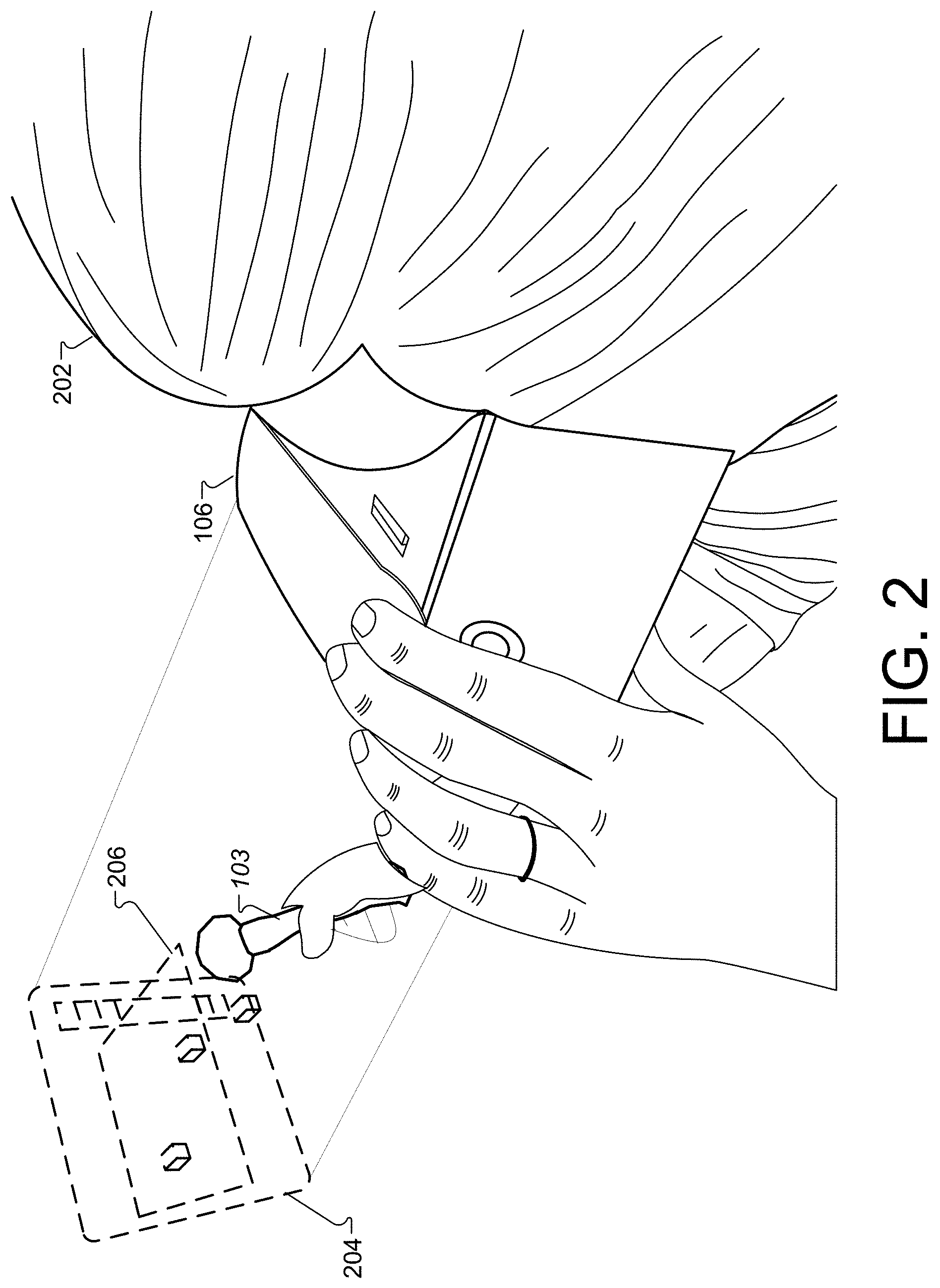
[0012] FIG. 2 is a diagram that illustrates a head mounted display (HMD) device accessing VR content with a computing device in the VR space of FIG. 1.
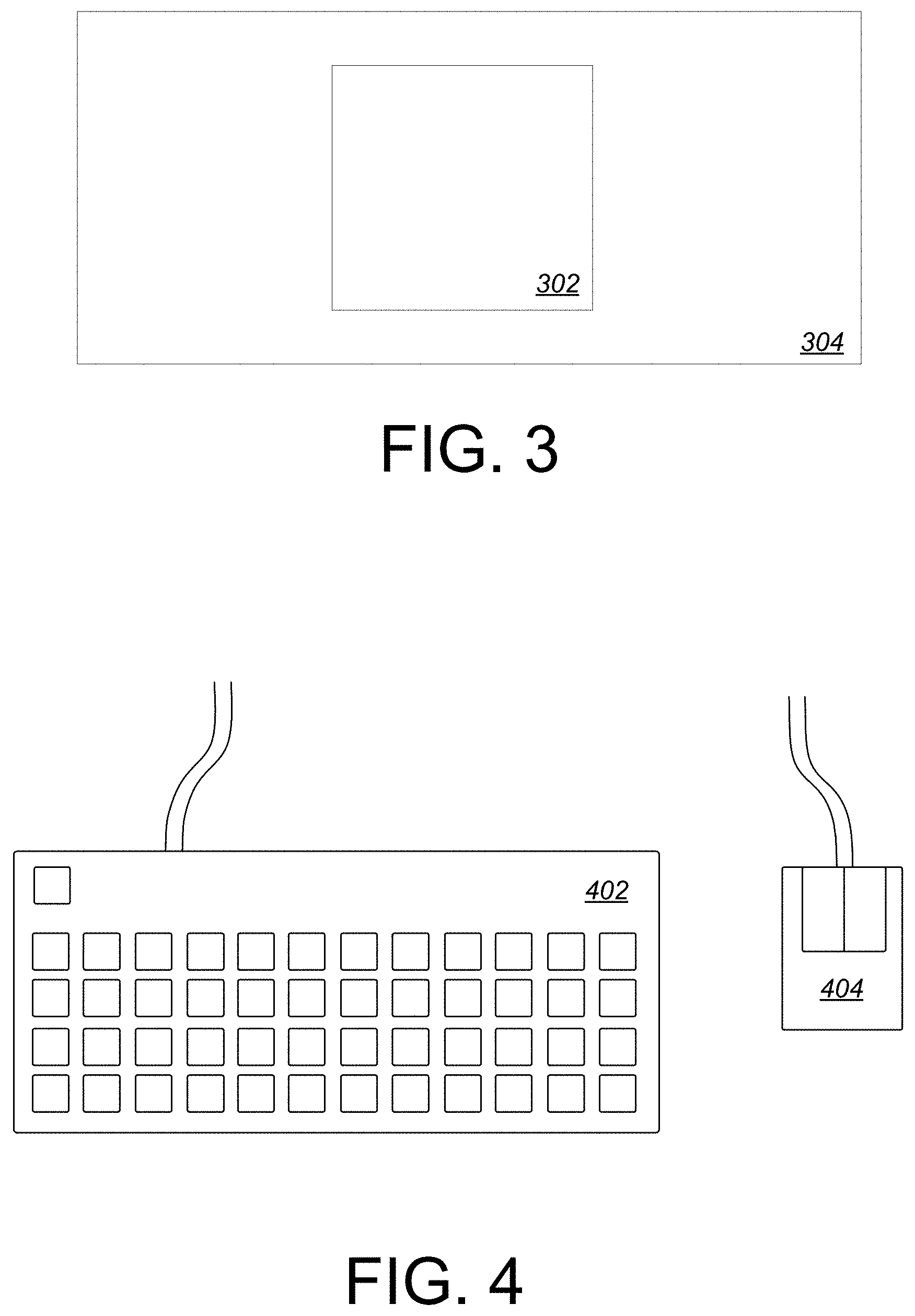
[0013] FIG. 3 is a perspective view of the object to be manipulated in virtual reality.
[0014] FIG. 4 is a perspective view of the computer keyboard and mouse input mechanisms.
[0015] FIG. 5 is a top-down view, showing a user pressing a key to modify the object in virtual reality.
[0016] FIG. 6 is a top-down view, showing a user releasing a key to revert modification of the object in virtual reality.
[0017] FIG. 7 is a top-down view, showing a user rotating the object in virtual reality by pressing a key and moving the computer mouse.
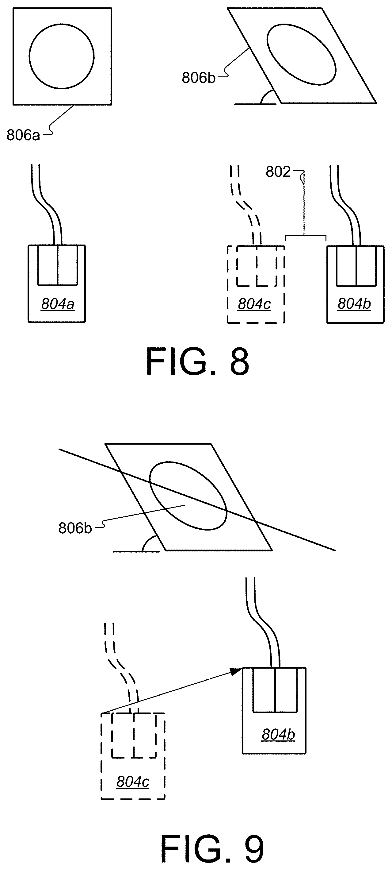
[0018] FIG. 8 is a top-down view, showing the direct relationship between computer mouse movement and object rotation.
[0019] FIG. 9 is a top down view, further explaining the relationship between computer mouse movement and object rotation.
[0020] FIG. 10 is a top-down view, showing a user pressing a key to modify the object in virtual reality.
[0021] FIG. 11 is a perspective view, showing a user translating the object in virtual reality by pressing a key and moving their head.
[0022] FIG. 12 is a perspective view, showing the direct relationship between user head movement and object translation.
[0023] FIG. 13 is a top-down view, showing a user pressing a button on the motion controller to modify the object in virtual reality, as well as a user releasing a button on the motion controller to revert modification of the object in virtual reality.
[0024] FIG. 14 is a top-down view, showing a user rotating the object in virtual reality by pressing a button on the motion controller and rotating the controller.
[0025] FIG. 15 is a top-down view, showing a user pressing a button on the smartphone to modify the object in virtual reality, as well as showing a user releasing a button on the smartphone to revert modification of the object in virtual reality.
[0026] FIG. 16 is a top-down view, showing a user rotating the object in virtual reality by pressing a button on the mobile device and rotating the mobile device.
[0027] FIG. 17 is a perspective view, showing a user translating the object in virtual reality by pressing a button on the mobile device and moving the mobile device.
[0028] FIGS. 18A-B are examples of various color spaces represented in two and three dimensions.
[0029] FIG. 19 is a perspective view of an example, three-dimensional color picker.
[0030] FIG. 20 is a screenshot of a functional prototype, three-dimensional color picker.
[0031] FIG. 21 is an example of a three-dimensional color picker augmented with additional information about the scene.
[0032] FIG. 22 is a perspective view of a GUI panel represented as a two-dimensional object in a virtual reality environment.
[0033] FIG. 23 is a perspective view, showing a user facing away from a GUI panel and the GUI panel is in a deactivated state.
[0034] FIG. 24 is a perspective view, showing a user facing a GUI panel and the GUI panel is in an active state.
[0035] FIG. 25 is a perspective view, showing the direct relationship between a user's two-dimensional input device and the location of a GUI panel in a virtual reality environment.
[0036] FIG. 26 is a perspective view, showing the direct relationship between the orientation of a user's three-dimensional input device and the orientation of a GUI panel in a virtual reality environment.
[0037] FIG. 27 is a perspective view of a user creating objects inside a virtual reality environment.
[0038] FIG. 28 is a perspective view of a user defining a set of objects as a frame.
[0039] FIG. 29 is a perspective view of a series of frames inside a virtual reality environment.
[0040] FIG. 30 is a perspective view of manipulation of a series of frames inside a virtual reality environment.
[0041] FIG. 31 is a perspective view of data associated with a frame inside a virtual reality environment.
[0042] FIG. 32 is a perspective view of playback of an ordered series of frames inside a virtual reality environment.
[0043] FIG. 33 is a perspective view of a user manipulating an invisible object inside a virtual reality environment.
[0044] FIG. 34 is a diagram showing a sequence of frames with associated data that can result in different outcomes during playback.
[0045] FIG. 35 represent perspective views of a user creating objects inside a virtual reality environment.
[0046] FIG. 36 represent perspective views of a user importing objects inside a virtual reality environment.
[0047] FIG. 37 is a perspective view of a head mounted display equipped with stereo cameras.
[0048] FIG. 38 is a side by side stereo view of the virtual reality environment.
[0049] FIG. 39 is a side by side stereo view of the virtual reality environment combined with the real world environment.
[0050] FIG. 40 is a side by side stereo view of the virtual reality environment combined with the real world environment, after a three-dimensional drawing has been created.
[0051] FIG. 41 is a side by side stereo view of the virtual reality environment with the created three-dimensional drawing, but with the real world environment turned off.
[0052] FIG. 42 is a perspective view of a user leaving the virtual reality tracking volume, and augment reality elements being activated.
[0053] FIG. 43 is a perspective view of a user manually activating augmented reality.
[0054] FIG. 44 is a top down view of the user's view direction activating augmented reality.
[0055] FIG. 45 is a perspective view of object recognition activating augmented reality.
[0056] FIG. 46 is a perspective view of a tracking marker that drives augmented reality visibility.
[0057] FIG. 47 is a front view of specific elements of the stereo camera feed being rendered into the virtual reality environment.
[0058] FIG. 48 is a front view of additional data related to real-world objects being rendered into a virtual reality environment.
[0059] FIG. 49 is a perspective view of a user at a computer with a depth-sensing camera facing them.
[0060] FIG. 50 is a perspective view of a user connected to another user via direct cable or Internet.
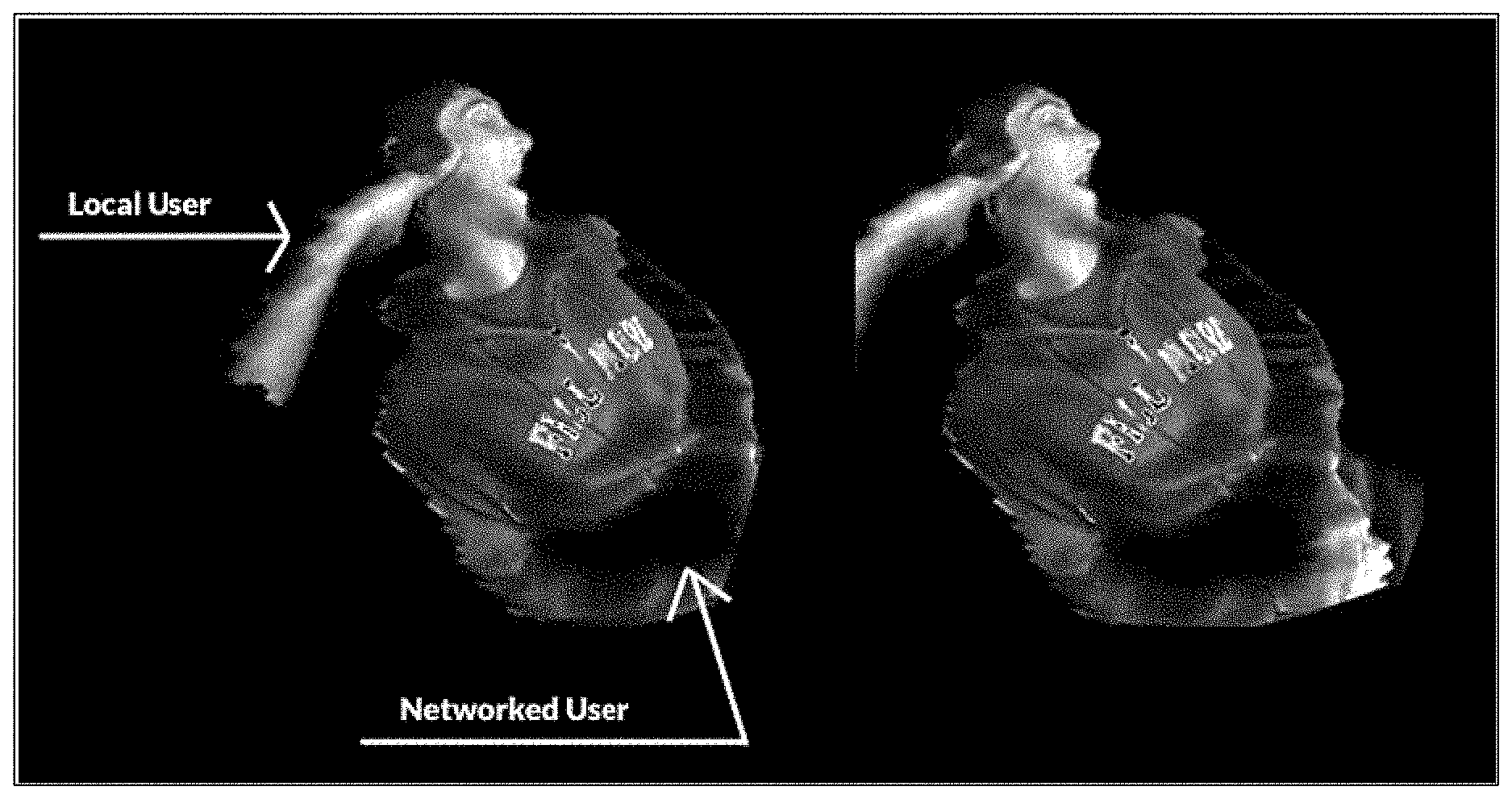
[0061] FIG. 51 is a virtual reality view of a local and networked user represented by a three-dimensional point cloud inside the virtual reality environment.
[0062] FIG. 52 is a virtual reality view of a local and networked user represented by a three-dimensional polygon mesh inside the virtual reality environment.
[0063] FIG. 53 is a perspective view of a user at a computer with a light-sensing camera facing them.
[0064] FIG. 54 is a virtual reality view of a user represented by a two-dimensional mesh inside a virtual reality environment.
[0065] FIG. 55 is a virtual reality view of a networked user represented with stylized accessories.
[0066] FIG. 56 is a perspective view of a user at a computer, interacting with a virtual reality environment.
[0067] FIG. 57 is a perspective view of multiple users, all at computers, interacting with a virtual reality environment.
[0068] FIG. 58 is a perspective view of multiple users connected together via direct cable or through the Internet.
[0069] FIG. 59 is a perspective view of a user connected to another user, with their input modifying the virtual reality environment of the other user.
[0070] FIG. 60 is a perspective view of a user connected to another user, with their microphone recording sounds and playing it through the speakers of the other user.
[0071] FIG. 61 is a perspective view of a user receiving sounds in the virtual reality environment from a specific location.
[0072] FIG. 62 is a perspective view of the relationship between the position of a user and the sounds users hear from them in a virtual reality environment.
[0073] FIG. 63 is a flow chart diagramming one embodiment of a process to provide a virtual reality environment (e.g., a VR space) in a three-dimensional environment in which a user can generate three-dimensional drawings.
[0074] FIG. 64 is an example screenshot representing a drawing plane and a selected brush panel in a VR space.
[0075] FIG. 65 is an example screenshot representing a drawing plane and a selected color panel in a VR space.
[0076] FIG. 66 is an example screenshot representing a tilted drawing plane with user drawn content depicted in the plane and user drawn content in a second plane in a VR space.
[0077] FIG. 67 is an example screenshot representing user drawn content in a VR space.
[0078] FIG. 68 is another example screenshot representing user drawn content in a VR space.
[0079] FIG. 69 is another example screenshot representing user drawn content in a VR space.
[0080] FIG. 70 shows an example of a computer device and a mobile computer device that can be used to implement the techniques described herein.
[0081] Like reference symbols in the various drawings indicate like elements.
DETAILED DESCRIPTION
[0082] This disclosure describes a variety of systems and methods for generating an environment in which to create a three-dimensional drawing inside a virtual reality environment (i.e., a VR space). Generating an environment in which a user can create three-dimensional drawings can include methods for controlling three-dimensional objects and content while inside a VR space, color representation and selection while inside the VR space, generating graphical user interfaces, sequencing frames for animation, augmenting existing three-dimensional virtual objects, augmenting real-world vision with computer graphics, representing a user's body while in a VR space, and collaborating amongst users and spectating while inside a VR space.
[0083] Content in the VR space can be generated and/or annotated by a user accessing toolsets (e.g., tool palettes) defined by the systems and methods described in this disclosure. The tool palettes may include brushes, cursors, panels, canvas simulators, shapes, surfaces, and texturizers, any or all of which can be used together to create and/or modify content in the VR space. In some implementations, the tool palette can include mechanisms to import preexisting files containing 2D or 3D objects including, but not limited to images representing data, art, photographs, models, and/or augmented reality content. In one non-limiting example, a user may annotate portions of the VR space by accessing one or more tools to import images of objects and use the tools in the tool palettes to add content or modify those images by drawing, painting, scribbling, moving, illuminating or shadowing, or otherwise generating and manipulating portions of the images in the VR space. The initially uploaded images and user-modified images can be manipulated around two or more axes during and after application of modifications/annotations. In addition, such images can be shared with other users for review and/or collaboration.
[0084] Particular implementations described in this disclosure may enable a user to draw in 3D in the VR space. The user can generate begin and end points by drawing in the air with an input device, such as a controller, sensor, or an input device. The user can point and direct the tracked device such that portions of the VR space can be drawn upon (e.g., with brush strokes, objects, annotations, texturizers, etc.). The systems described below can track the drawing motions of the user, generate artistic or annotated content based on those motions, and provide for moving around the content, the x-y plane or y-z plane (or other coordinate system) that the content is being generated in. For example, the user can lift the input device into the VR space (which can show the user her hands via the HMD device). The user can begin to draw/paint on a selected surface normal (oriented in 3D space). If the user begins to draw a circle surrounding her body, the circle will appear from the input device as the user begins to draw the circle. The input device may be depicted to the user as a paintbrush, pen, controller, or other selected tool. Upon completing any portion of her drawing, the user can tilt the plane/surface normal to begin drawing in another vector space (e.g., another dimension or plane). In the circle drawing example, the user may complete the circle surrounding herself with a shape that appears to be a hula hoop. The user can move the hula hoop around within the VR space as she desires.
[0085] In some implementations, the systems and methods described in this disclosure can provide for importing objects into the VR space. For example, a user can upload objects into a system hosting a VR application. The VR application can provide the objects for display in the VR space. The display can be viewed by a user accessing an HMD device. Imported objects can be used to provide a visual reference for a user beginning to draw in three-dimensions within the VR space. The objects can be traced, or in some implementations, can be used as a guide in which the user can judge distances and shapes for recreating a drawing or other notation for the object. In some implementations, the user can draw on the imported object to annotate portions of the object. In some implementations, the imported objects may be 2D or 3D and can include 3D models, scans, mesh models, depth collages, etc. Imported images can include any displayable file type including, but not limited to a CAD file, a jpeg file, a png, a bitmap file, or other file type. In some implementations, the user can export images generated, modified, or otherwise changed within the VR space.
[0086] In a non-limiting example, a user can view sample sketches, draw content/sketches, and import or export sketches from or to an animated .gif. Example controls may include using a keyboard, a mouse, or a 3D controller to move a pointer. The pointer may represent an area under a sketch tool depicted in the VR space. For example, the pointer may represent an area in which a sketch is being generated. Example mouse motions can include using a left mouse click to draw, using a middle mouse click to pan along a VR space x-y plane, using a right mouse click to pan along world z-axis, and using a double click middle mouse button to reset the pointer to the center of a sketching surface.
[0087] Example keyboard keys that can control content in the VR space include holding the control key to rotate the sketching surface, holding the control key and left mouse button to rotate the sketching surface along a roll axis, holding the shift key to lock the sketching surface to a camera, using the caps lock key to toggle grid locked mode on the sketching surface, holding the tab key to adjust a brush size, pressing a spacebar to reset the sketching surface to the center of scene, double tapping the control key to reset the sketching surface orientation, selecting the (z) key to undo a stroke or action, pressing the (x) key to redo a stroke or action. Such controls can also be configured to translate a surface or object in the VR space while the particular surface or object is locked.
[0088] In addition, the systems and methods described herein can be configured to detect and react to movements such as head tilt behavior and/or eye gaze behavior associated with a user and an HMD device being worn by the user. The systems and methods can be used to detect and react accordingly to particular tool palettes generated for drawing in 3D space.
[0089] FIG. 1 is a block diagram of an example system for providing a virtual reality environment (e.g., a VR space) in a 3D environment in which a user can generate 3D drawings. In general, the system 100 may provide the 3D VR space, drawing tools, and VR content for a user to access, view, and interact with using the methods, components, and techniques described herein. In particular, system 100 can provide the user with options for accessing the images, content, virtual objects, and VR controls using eye gaze, hand gestures, head movements, and/or other user-based movements within the VR space. For example, a user can generate 3D drawings in portions of the VR space and interact with such drawings using input devices, and tools configured to generate artistic drawings or annotations on drawings or other VR objects.
[0090] As shown in FIG. 1, the example system 100 includes a plurality of computing devices that can exchange data over a network 101. The devices may represent clients or servers and can communicate via network 101, or other network. The client devices may include a mobile device, an electronic tablet, a laptop, a camera, a game controller, VR glasses or HMD device, or other such electronic device that may be used to access VR content.
[0091] The example system 100 includes a mobile device 102, a game controller 103, a laptop computing device 104, head mounted display (HMD) device 106, and VR drawing system 108. Devices 102, 103, 104, and 106 may represent client devices. Mobile device 102, game controller 103, laptop 104, and HMD device 106 can include one or more processors and one or more memory devices. The devices 102-106 can execute a client operating system and one or more client applications that can access, control, and/or display VR content on a display device included in each respective device. The VR drawing system 108 may represent a server device. In general, VR drawing system 108 may include any number of repositories storing images, objects, content and/or virtual reality software modules that can generate, modify, or execute display of virtual reality scenes and content.
[0092] The HMD device 106 may represent a virtual reality headset, glasses, eyepiece, or other wearable device capable of displaying virtual reality content. In operation, the HMD device 106 can execute a VR application 110, which can playback received and/or processed images to a user. In some implementations, the VR application 110 can be hosted by or interfaced with one or more of the devices 102, 103 104, 106, or 108, shown in FIG. 1.
[0093] In some implementations, the mobile device 102 can be placed and/or located within the HMD device 106. The mobile device 102 can include a display device that can be used as the screen for the HMD device 106. The mobile device 102 can include hardware and/or software for executing the VR application 110.
[0094] Additional devices are possible and such devices may be configured to be substituted for one another. In some implementations, the devices 102, 103, 104, 106, and 108 can be laptop or desktop computers, smartphones, personal digital assistants, portable media players, tablet computers, gaming devices, or other appropriate computing devices that can communicate, using the network 101, with other computing devices or computer systems.
[0095] In the example system 100, the VR drawing system 108 can include a VR application 110. The VR application 110 can be configured to execute on or interface to any or all of devices 102, 103, 104, 106, and 108. The HMD device 106 can be connected to device 102, device 103, or device 104 to access VR content on VR drawing system 108, for example. Devices 102-104 can be connected (wired or wirelessly) to HMD device 106, which can provide VR content for display and interactive drawing.
[0096] In the event that the HMD device is wirelessly connected to devices 102-104, the connection may include use of one or more of the high-speed wireless communication protocols described herein. In the event that the HMD device 106 is wired to devices 102-104, a wired connection can include a cable with an appropriate connector on either end for plugging into devices 102-104. For example, the cable can include a Universal Serial Bus (USB) connector on both ends. The USB connectors can be the same USB type connector or the USB connectors can each be a different type of USB connector. The various types of USB connectors can include, but are not limited to, USB A-type connectors, USB B-type connectors, micro-USB A connectors, micro-USB B connectors, micro-USB AB connectors, USB five pin Mini-b connectors, USB four pin Mini-b connectors, USB 3.0 A-type connectors, USB 3.0 B-type connectors, USB 3.0 Micro B connectors, and USB C-type connectors. Similarly, the wired connection can include a cable with an appropriate connector on either end for plugging into the HMD device 106 and devices 102-104. For example, the cable can include a Universal Serial Bus (USB) connector on both ends. The USB connectors can be the same USB type connector or the USB connectors can each be a different type of USB connector.
[0097] In some implementations, one or more content/drawing servers (e.g., VR drawing system 108) and one or more computer-readable storage devices can communicate with the computing devices 102 or 104 using network 101 to provide VR content and selectable drawing tools to the devices 102-106. In some implementations, the network 101 can be a public communications network (e.g., the Internet, cellular data network, dialup modems over a telephone network) or a private communications network (e.g., private LAN, leased lines). In some implementations, the computing devices 102-108 can communicate with the network 101 using one or more high-speed wired and/or wireless communications protocols (e.g., 802.11 variations, WiFi, Bluetooth, Transmission Control Protocol/Internet Protocol (TCP/IP), Ethernet, IEEE 802.3, etc.).
[0098] In some implementations, the mobile device 102 can execute the VR application 110 and provide content and drawing capabilities to a user accessing the VR space. In some implementations, the laptop computing device 104 can execute the VR application 110 and can provide content and drawing capabilities to a user accessing the VR space. The one or more servers and one or more computer-readable storage devices can communicate with the mobile device 102 and/or laptop computing device 104 using the network 101 to provide content and drawing capabilities for display in HMD device 106.
[0099] The VR drawing system 108 includes a movement tracking module 112 can be configured to track user position and motion within the VR space as well as tracking drawing content. For example, the movement tracking module 112 can employ a geometrical concept to determine user movement of input devices to generate drawing content and brush strokes, in particular. The geometrical concept is described as a quad. Quads can be generated and manipulated by quad generator 113. The quad generator may be configured to generate triangular geometries for tracking position information within the virtual reality environment. The position information may correspond to an initial input location and a current input location for the three-dimensional input device. The triangular geometries may be generated each time the three-dimensional input device is moved. The quad generator can generate triangular geometries that are adapted to be combined to generate drawing content in the virtual reality environment. The drawing content can be configured with a user-selected texture, color, and/or shade.
[0100] Quads can include at least two triangular geometries (i.e., triangles) that can be used to define positional information for the pointer object (e.g., represented as a brush tip or input mechanism position). The triangular geometries include at least two triangles defining a three dimensional starting point for a cursor, represented in the virtual reality environment, and a three-dimensional ending point for the cursor. The positional information can include a beginning pointer location and a current pointer location. As a user moves the pointer object around in 3D space, the system 100 can generate a quad and positional information corresponding to the quad. The normal of one or both of the triangles that define the quad can be used to define a forward vector. That is, the normal of the pointer object represents the normal of a first triangle in the quad. Similarly, the normal of the pointer object in the current position represents the normal of the second triangle. A right vector can be obtained by performing the cross product of the two normals. Each movement the user makes can be used to generate quads, and each quad can be stitched or appended together to generate a smooth brushstroke (e.g., ribbon of color, texture, line drawing, or other object or artifact representing user movement when generating 3D drawing content in the VR space).
[0101] The look of a quad can be is defined by the texture, material, color, and shade or luminance. The texture is a property of the material, with the material being unique per brush and functioning to define the behavior the texture may have with respect to lighting in a VR space (e.g., scene). The color of a quad is set per vertex, and defined by the user, as described in detail below. The shade can be applied to the quad using various inputs from the VR space to modify the look of the quad. Inputs that can affect the shade include color, time, audio input, world space position, model space position, and light/luminance values, as described in detail below.
[0102] In some implementations, the movement tracking module 112 can include capability for head tracking. For example, the HMD device 106 can determine directions that a user's head is moving. The user can nod, turn, or tilt her head to indicate which tool to select, which panel to access, and/or which other functionality to invoke or revoke.
[0103] In some implementations, the movement tracking module 112 may also include capability for gaze tracking. Gaze tracking can interface with one or more sensors, computing systems, cameras, and/or controls to detect gaze/eye movement associated with the user while the user is in the VR space. The one or more sensors, computing systems, cameras, and/or controls may be housed in HMD device 106, for example. The gaze tracking can track or monitor the direction of a user's eye gaze (i.e., tracking or monitoring where/which direction the user is looking). In general, gaze tracking may include tracking both the orientation and location of one eye or both eyes with respect to a defined coordinate system.
[0104] In operation of VR drawing system 108, the user is in control of the pointer object. When the pointer object is activated, the system 108 can record the point object position. As the pointer object moves, the system 108 can measure the difference from a previously recorded pointer object position and generate a new quad in response to the pointer object being moved by the user. The generated new quad may be represent two triangles, with the forward vector defined by the distance between the points, the pointer forward as the quad normal, and the cross product of those two defining the right-hand vector. The width of the quad may be defined by the right-hand vector multiplied by the current brush size, which may be controlled by the user.
[0105] In some implementations and for certain brush types, the system 108 can stitch the quads together to create a smooth, ribbon effect. Stitching the quads together may include matching a leading edge of a previous quad with a trailing edge of the current quad. Midpoint mathematical calculations can be used to ensure quad triangles do not fold in on other quad triangles. In addition, if the dot product of the forward vectors of two sequential quads is greater than an amount relative to the vector size multiplied by a scalar, the system 108 can trigger a break of the ribbon, which can begin a new sequence of quads. In some implementations, smoothing algorithms can be applied to the normals of sequential quads to generate a consistent look to the ribbons/brushstrokes.
[0106] In some implementations, the system 108 may not stitch the quads together and instead may assign random orientations to a forward vector, which can function to generate a spray paint effect. Such an effect may be associated with particle brushes that can be selected from a brush tool palette. In one example, instead of generating and stitching quads, the system 108 can generate billboard stripes.
[0107] Panels
[0108] The VR drawing system 108 also includes tool palettes 114 including, but not limited to panels 118. The VR application 110 can provide a number of panels 118 within the VR space. Panels 118 may be represented as 2D or 3D interactive images in the VR space. In one example, panels are 3D objects that can include a number of user-selectable controls or content. The panels may be affixed to content in the VR space or may appear floating in the VR space and at the ready to receive user selections or simply provide visual guidance. In some implementations, the panels may light up to indicate available tools, drawing planes, pointer locations, or other indicators that can trigger head or eye movement from a user.
[0109] In some implementations, a pointer object can be positioned on a panel and a user can move around the pointer object on the panel to select portions of the panel. In some implementations, one or more panels may be positioned by the system 108 (or the user). For example, the user may select a first panel by grabbing the panel and moving it in the 3D VR space. The user may choose to make the first panel a focus and as such may center the panel in a central position. The user may choose to select another panel that hosts brushes and paint tools, for example, and may position that panel to a left or right side, depending on the user's handedness. Similarly, a third panel, such as a color panel 116 can be selected and moved around at the convenience of the user or at a default instantiated by the system 108.
[0110] Color panel 116 may represent a three-dimensional tool palette configured to provide, in a VR space, at least one color palette menu represented as a three-dimensional cube in three-dimensional space. The cube may include a two dimensional saturation area including a cross section of spaces representing an intensity for a number of different hues. The intensity may define a degree to which each hue differs from white. The intensity may be depicted numerically, graphically, textually, or both. The cube also includes one-dimensional hue area including selectable hues. Upon selection of one of the hues the color panel 116/cube may automatically adjust the two dimensional saturation area to reflect a position of at least one of the selected hues in the three-dimensional cube.
[0111] In some implementations, a number of panels can be configured to attach to a location of a 3D motion/position tracked controller. The panels can be attached in a wand formation around the controller, for example. The panels may be arranged around the controller (e.g., and the users hand if the user is holding the controller) similar to a painters palette, in which the user can rotate her hand to rotate the controller and trigger display of additional panels and options in a circular fashion.
[0112] In some implementations, the system 100 can detect a user eye gaze or head movement and use such input to activate/select a particular panel. For example, the user can nod toward a panel to activate the panel and begin moving, selecting, or otherwise interface with the panel.
[0113] Brushes
[0114] The tool palettes 114 also include, but are not limited to brushes 120. Brushes 120 can apply to any tool used to generate drawings, objects, and/or content in the VR application 110. A brush may be defined by the material and shader associated with the brush. The material optionally contains a texture. The brush color is defined by the user. The material, shader, texture, and color may define the look of a quad generated by a selected brush.
[0115] The following tables describe a number of brush panel and drawing panel options and effects that can be accessed in the VR space using the point to select a brush or adjust a brush size.
TABLE-US-00001 TABLE 1 Brush Panel Options Brush Panel Effect Ink Textured lines that always face the camera Streaky Ink Textured lines that always face the camera Pencil Thin lines that always face the camera Additive Ink Textured lines that always face the camera, using additive color properties Flat Brush Flat, oriented paint quads Coarse Brush Textured, oriented paint quads Splatter Brush Textured, oriented paint quads Square Brush Flat, oriented paint quads Star Brush Creates star particles Smoke Brush Creates smoke particles Shrapnel Brush Creates sharp, angular particles Light Brush Flat lines that always face the camera and emit light
TABLE-US-00002 TABLE 2 Drawing Options Panel Drawing Options Panel Response New Sketch Clears scene Sample Sketch 1 Test scenes to show example sketches Sample Sketch 2 Sample Sketch 3 Scene Lights Use two directional lights for shadow casting Ambient Lights Use only flag, white ambient light No Lights Disables lighting to highlight Light Brush strokes Unlocked Rotation Free rotation with Ctrl key Yaw Only Rotation Rotation is locked to the Yaw axis on the Sketching Surface Pitch Only Rotation Rotation is locked to the Pitch axis on the Sketching Surface Roll Only Rotation Rotation is locked to the Roll axis on the Sketching Surface Undo Undoes last brush mark Redo Redoes last undone brush mark. Toggle Grid Lock Toggles Grid Locked mode on Sketching Surface Auto-Orient Automatically adjusts the orientation of the sketching surface after a rotation to ensure `up` on the mouse is `up` on the Sketching Surface Auto-Gif Exports an animated .gif file of the current scene. The focal point of the exported .gif is the current center of the Sketching Surface. Animated .gif files are saved in the Gifs folder
[0116] In one example, instead of free-form drawing, a user can select a constraining tool to paint or draw a particular shape. One such example includes a straight edge tool that can be selected to provide a straight line from a beginning to ending point selected by the user and in the selected brush stroke. Another example includes a mirror brush that can be selected to free form mirror a drawing that the user is actively drawing in the VR environment. The mirror brush can mirror such a drawing left to right, top to bottom, or any other 2D or 3D mirroring angle. In addition, the mirror brush can replicate to any number of axes. For example, the mirror brush can be set to mirror across axes such that a 3D mirrored drawing can be replicated across all three axes in 3D. Functionally, the system 100 may be receiving input from a user at a pointer and can mirror the pointer movements across several planes of space in the VR space. The mirroring may be a mathematical reflection across the planes. The mirroring can occur simultaneously to the user generating the drawing.
[0117] In some implementations, the brush panel can include a brush selector in which brushes, patterns, colors, and textures can be selected for use in the VR space. The selection mechanism can appear to the user in the VR space as a pointer that turns into a spherical shape indicating that selections are possible. The user can position the sphere around to select a brush for example, the VR application 110 can provide a pop up or tool tip message that indicates sizes, colors, and other attributes. The user can switch between brushes using the brush panel that can appear and reappear in 3D space as requested by the user.
[0118] FIG. 2 is a diagram that illustrates an HMD device 106 (or VR device) accessing VR content with a mobile device 102, for example. In the example shown in FIG. 2, a user 202 may be accessing VR drawing system 108 by interfacing with content in system 108 (with controller 103). The user 202 may be accessing a color palette 204 and may be drawing content within a panel 206. Color palette 204 and panel 206 are shown as dotted line figures because the depicted content is provided within the VR space that the user 202 is viewing in HMD 106.
[0119] To begin accessing VR drawing system 108 and view panel 206, the user 202 can put on the HMD device 106 by placing the device 106 over the eyes of the user 202. In some implementations, referring to FIG. 1, the HMD device 106 can interface with/connect to mobile device 102 and/or controller 103, for example, using one or more high-speed wired and/or wireless communications protocols (e.g., WiFi, Bluetooth, Bluetooth LE, USB, etc.) or by using an HEMI interface. The connection can provide the content to the HMD device 106 for display to the user on a screen included in the device 106.
[0120] One or more sensors can be included on controller 103 and can be triggered, by users accessing device 103 and HMD device 106, to provide input to the VR space. The sensors can include, but are not limited to, a touchscreen, accelerometers, gyroscopes, pressure sensors, biometric sensors, temperature sensors, humidity sensors, and ambient light sensors. The controller 103 can use the sensors to determine an absolute position and/or a detected rotation of the controller 103 in the VR space that can then be used as input to the VR space. For example, the controller 103 may be incorporated into the VR space as a mobile phone, a paint brush, a pencil or pen, a drawing tool, a controller, a remote, or other object etc. Positioning of the controller 103 by the user when incorporated into the VR space can allow the user to position the mobile phone, paint brush, pencil or pen, drawing tool, controller, remote, or other object in the VR space.
[0121] In some implementations, one or more input devices can be used to access content and provide input to the VR space. The input devices can include, but are not limited to, a touchscreen, a keyboard, one or more buttons, a trackpad, a touchpad, a pointing device, a mouse, a trackball, a joystick, a camera, and a microphone. A user interacting with an input device can cause a particular action to occur in the VR space.
[0122] Object Control
[0123] In general, control mechanisms of objects in a virtual reality environment may not translate well to conventional input mechanisms. Virtual reality environments are typically built in three dimensions, but conventional input mechanisms, like the computer keyboard and mouse, are built for two-dimensional environments. The following describes a method of manipulating an object in a three-dimensional virtual reality environment with computer keyboard and two-dimensional input mechanisms. A two-dimensional input mechanism can be, but is not limited to, a computer mouse, a stylus, or a touchpad.
[0124] Referring now to the object control with two-dimensional input feature in more detail, in FIG. 3, there is shown an object 302 that is viewable in a VR space 304. FIG. 4 shows the conventional computer keyboard 402 and mouse 404 input mechanisms.
[0125] Referring now to FIG. 5, it is shown that the use of a key 502 on the keyboard 504 can cause a visible change on the object 506 in the VR space. FIG. 6 shows the converse of this concept, in that when the use of the key 502 on the keyboard 504 has stopped, the visible change on the object will cease to be visible, as shown by unselected object 508.
[0126] Referring now to FIG. 7, it is shown that movement of the mouse 702 while the use of a key 704 on the keyboard 708 can rotate the object 710. In further detail, shown on FIG. 8, the amount of movement 802 of mouse 804a-c is directly related to the amount of rotation on the object, shown by object 806a and object 806b.
[0127] The method by which the object is rotated is shown in FIG. 9 and described as follows: the position of the mouse 804c is recorded when the use of the key on the keyboard begins (FIG. 8). The vector of change from a position of the mouse from 804c to 804b may be used as input to the rotation amount of the object 806b in virtual reality. The rotation amount is defined by an angle and a rotation axis. The angle is defined as a direct function of the distance of vector of change, multiplied by a scalar. The axis is defined by the cross product of the vector of change and the object's facing normal. The rotation is applied to an object when the use of the key on the keyboard ends.
[0128] Referring now to FIG. 10, it is shown that the use of a key 1002 on the keyboard 1004 may cause a visible change on the object 1006 in the VR space. If the user were to lift her finger 1008, the object 1006 would be removed from view, thereby depicting the converse of the concept in FIG. 10, in that when the use of the key on the keyboard has stopped being pressed, the visible change on the object will cease to be visible. In some implementations, if the user holds a shift key on the keyboard, a drawing plane/cutting plane may be locked to the user's head position. In particular, if the user holds the shift key and leans back, the system 100 can bring the cutting plane forward. If the user holds the shift key on the keyboard and turns her head to the left, the cutting plane can be adapted to rotate leftward.
[0129] In some implementations, the cutting plane may represent a mathematical, 2D plane in 3D space. The purpose of the cutting plane is to constrain interactions from a user to a subset of the 3D space, for simplicity's sake. The cutting plane can provide a 3D view in a way that the user can select at least two dimensions in which to draw. The concept of the cutting plane could be generalized to any shape or size within VR space. For example, instead of a plane, the shape of a cutting area could be a sphere or cube or a complex shape including symmetrical or asymmetrical polygons. The fundamental purpose is to limit the range of interaction for the ease of the user.
[0130] In some implementations, if the user holds the control key on the keyboard, the system 108 can switch to a pivoting mode on the cutting plane. When the user moves the mouse, the object (and the plane depicting the object) can be rotated relative to where the user moves the mouse. For example, if the user moves the mouse directly to the right (i.e., vector: X:1, Y:0, Z:0), the system 108 can generate a bisecting line on the cutting plane.
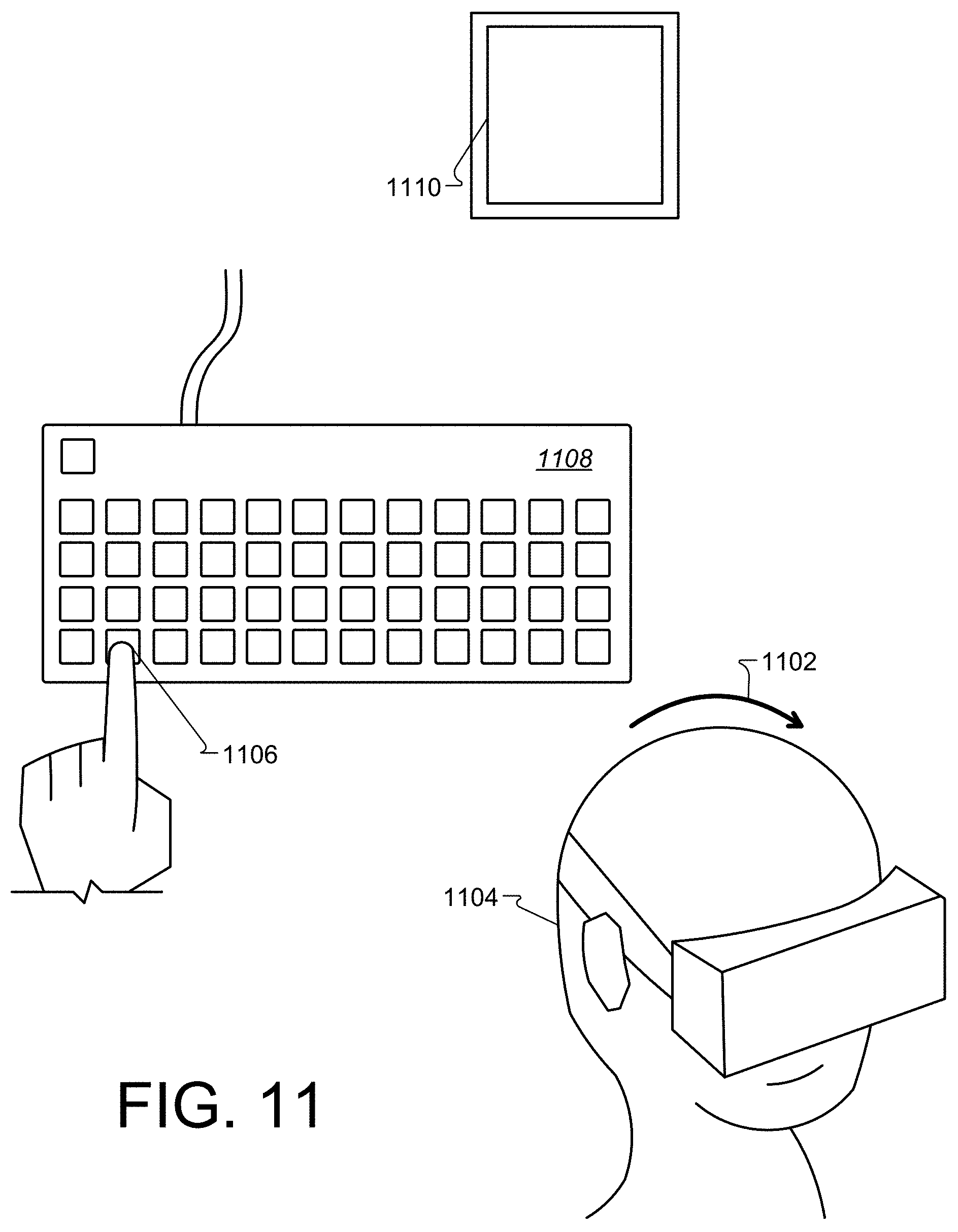
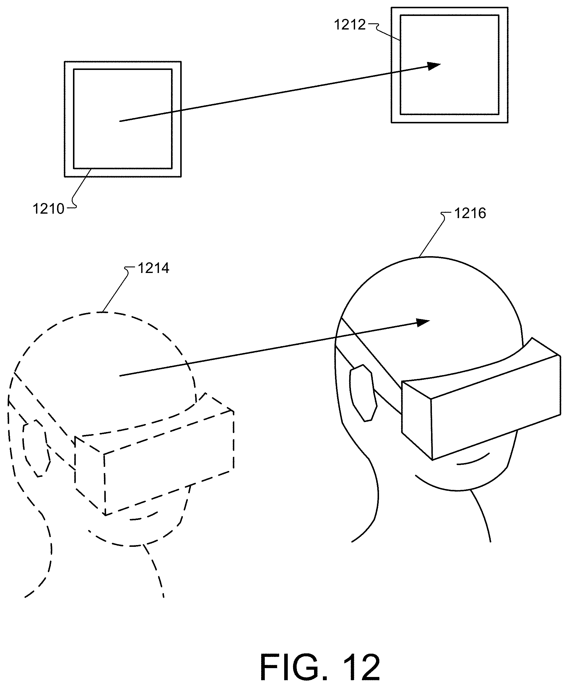
[0131] Referring now to FIG. 11, it is shown that a movement (indicated by arrow 1102) of the user's head 1104 while a key 1106 on the keyboard 1108 is pressed can translate (e.g., move, tilt, change, etc.) an object 1110 in some fashion. In further detail, shown on FIG. 12, the amount of movement of the user's head is directly related to the amount of translation on the object.
[0132] The method by which the object 1110 is translated is shown in FIG. 12 and described as follows: the position of the user's head moves from the position shown at head position 1214 to the position shown at head position 1216. The position change from 1214 to 1216 is recorded when the use of the key on the keyboard begins. The vector of change from this position change is used as input to the translation amount of the object in virtual reality. The translation is applied to the object when the use of the key on the keyboard ends.
[0133] Example use cases of the object control with two-dimensional input feature include the ability to position dialog windows in a 3D program, a sketching surface for drawing, building walls in an architecture tool, or game elements in a video game.
[0134] In operation, using the keyboard and mouse can allow movement in three dimensions. Namely, the keyboard represents a 1-dimensional input while the mouse represents a 2-dimensional input. Being that the VR space is 3D, combining the keyboard and mouse can allow for movement in all three dimensions. For example, using the keyboard and mouse, a 2-dimensional drawing/cutting plane can be accessed in the 3D VR space and when a user moves the mouse around, the pointer of the mouse (and a pointer or beginning point for creating drawings in the VR space) can move around on that plane. A drawing can be generated by clicking and dragging the mouse and additional movements and cutting plane can be accessed by holding down certain keys on the keyboard. In particular, the orientation and position of a particular cutting plane can be manipulated using keystrokes and mouse movement and input. In a non-limiting example, a user can begin to draw a side of a building and then can rotate the cutting plane (e.g., tilt the cutting plane) and then begin to draw or paint additional content, which can appear in the VR space as if the user is generating/drawing/painting two sides of the building. In some implementations, if the user holds a shift key on the keyboard, the cutting plane may be locked to the user's head position. In particular, if the user holds the shift key and leans back, the system 100 can bring the cutting plane forward. If the user holds the shift key on the keyboard and turns her head to the left, the cutting plane can be adapted to rotate leftward.
[0135] In a non-limiting example, the user may select a stylus and use the stylus as a two-dimensional input mechanism to interact similar to the mouse input described above. Similarly, a mobile device can be used to draw in the VR space and can function to determine orientation information during use and to communicate such orientation data and movement data to VR application 110, for example. In one mobile device example, a user can perform a pinch, a swipe, a shift, a tilt, or other input to signal the VR application about object movements within the VR environment. In this example, tilting the mobile device to the right may cause the object being drawn to be tilted to the right. In another example, tilting the mobile device to the right may begin a rotation of the object to the right.
[0136] In another non-limiting example, the user may select a controller, such as controller 103, configured to provide three-dimensional input. The controller can generally determine orientation and position information within the VR space. A user can select one or more buttons or controls on the controller to activate movement of objects and drawing content within the VR space.
[0137] The following is a method of manipulating an object in a three-dimensional VR space with a motion controller input. Referring now to the object control with three-dimensional input feature in more detail, in FIG. 13 there is shown an object 1302a that is viewable in a VR space and is modified according to user manipulation of controller 1304a. For example, using a button (not shown) on controller 1304a-b may cause a visible change on the object in the VR space. It also shows the converse of this concept, in that when the use of the button on the motion controller 1304a has stopped, the visible change on the object (shown at 1302b) may cease to be visible.
[0138] Referring now to FIG. 14, it is shown that rotation of a motion controller 1404a to 1404b while the use of a button on the motion controller (not shown) can rotate a VR object 1402a to 1402b. In further detail, the amount of rotation 1406 on the motion controller, may be directly related to the amount of rotation 1408 on the object 1402b. The method by which the object 1402a is rotated includes recording the orientation of the motion controller when the use of the button on the motion controller 1404a begins. The quaternion difference from this rotation is used as input to the rotation amount of the object in the VR space. The rotation is applied to the object 1402a when the use of the button on the motion controller ends. The use of a button on the motion controller 1404a can cause a visible change on the object 1402a in the VR space. The converse is also true, that when the use of the button on the motion controller 1402a has stopped, the visible change on the object (shown by 1410) may cease to be visible.
[0139] In general, the amount of movement of the motion controller is directly related to the amount of translation on the object 1402a. The translation can occur by recording the position of the motion controller 1404a to 1404b when the use of a button (not shown) on the motion controller 1404a begins. The vector of change from this position can be used as input to the translation amount of the object (from 1402a to 1402b) in the VR space. The translation is applied to the object when the use of the button on the motion controller 1404b ends.
[0140] Example use cases of the object control with three-dimensional input feature include the ability to position dialog windows in a 3D program, a sketching surface for drawing, building walls in an architecture tool, or game elements in a video game.
[0141] Referring now to FIG. 15, it is shown that the use of a touch on the mobile device 1502a can cause a visible change on an object 1504a in the VR space. The converse is also true that when the use of the touch on the mobile device 1502a has stopped (noted at mobile device 1502b, the visible change on the object 1502a will cease to be visible, as shown by object 1504b.
[0142] Referring now to FIG. 16, it is shown that rotation 1602 of the mobile device 1502a to 1502b while the use of a touch on the mobile device will rotate 1602 the object 1504a to 1504b, as shown by rotation 1602. In further detail, the amount of rotation 1602 on the mobile device, is directly related to the amount of rotation 1604 on the object. The orientation of the mobile device is recorded when the use of the touch on the mobile device begins. The quaternion difference from this rotation is used as input to the rotation amount of the object in virtual reality. The rotation is applied to the object when the use of the touch on the mobile device ends.
[0143] Referring now to FIG. 17, it is shown that the use of a touch on the mobile device 1502a can cause a visible change on the object 1504a in the VR space. The converse of this concept may also hold, that when the use of the touch on the mobile device has stopped (at 1502b), the visible change on the object may cease to be visible (at 1504b). Movement of the mobile device while a touch on the mobile device is used will translate the object. The amount of movement of the mobile device may be directly related to the amount of translation on the object.
[0144] In general, the position of the mobile device may be recorded when the use of the touch on the mobile device begins. The vector of change from this position may be used as input to the translation amount of the object in virtual reality. The translation is applied to the object when the use of the touch on the mobile device ends.
[0145] Example use cases of the object control with smartphone feature include the ability to position dialog windows in a 3D program, a sketching surface for drawing, building walls in an architecture tool, or game elements in a video game.
[0146] Color Representation
[0147] Color is a three dimensional quantity but is traditionally represented on a two dimensional surface. The following description includes a method of representing, and choosing, a color in a 3D VR space by representing that color in 3D.
[0148] Color can be a complex concept, and may commonly be reduced to a 3D color space for use in computer graphics. By defining a color space, colors can be identified numerically by particular coordinates. In virtual reality, true 3D color objects can be generated and manipulated.
[0149] FIG. 18A depicts color in two dimensions for HSV 1802a, RGB 1804a, and Lab 1806a. FIG. 18B depicts color in three dimensions for HSV 1802b, RGB 1804b, and Lab 1806b. By rendering these color spaces into the VR space as true 3D objects, the user can comprehend and visualize all accessible colors.
[0150] In order to render the color space without obscuring colors inside the volume, users can select a two-dimensional slice by positioning a cross section inside the volume. Colors in front of the slice should not be represented, as they will obscure colors on the cross section. Colors behind the cross section can be rendered with partial, or full, transparency.
[0151] Referring now to FIG. 19, it is shown that one way of positioning the cross section is to define its position as one of the color space axis 1902, 1904a, and 1904b. Manipulating the value of one or more of these axes (1902, 1904a, 1904b) changes the position in 3D space of the cross section from cross section 1906a to cross section 1906b. The colors on the cross section 1906b updates accordingly. A single 2D position on the cross section 1906a, combined with the value of that third axis 1904a or 1904b, fully describes the coordinate of a desired color. The cross section 1906b can also be positioned in other ways described above with respect to object control. For example, motion controller or head position can be used to manipulate the cross section.
[0152] Referring now to FIG. 20, an HSV (e.g., 1802b) color picker is shown. It should be noted viewing the color in three-dimensions provides a more accurate view into what colors are available for selection, as the narrowing at the bottom of the cone (as all colors converge on black) is visualized. As shown, a screenshot 2000 of a prototype application of a three-dimensional color picker with a color space 2002.
[0153] In general, the concept of a three dimensional color space, and color picker, can be expanded to contain information more complex than just the three-dimensional color spaces. In this example, colors that are in use in the VR drawing system 108 in the VR space are highlighted allowing users to visualize their color palette in three dimensions. Hues 2004 are shown here on the right side of color space 2002. The hues range from lightness/bright or lightness and darkness, which can be depicted as a color, shade, or numerical value. Sliding a hue slider (not shown) up and down can cause the color palette 2006a to physically (e.g., virtually) move in the VR space, as shown by growing color palette 2006b.
[0154] As shown in FIG. 21, a screenshot 2100 shows a color palette 2100 that can be depicted in 3D and as a 3D colorbox (e.g., color volume). The palette 2100 may appear 3D to the user and be modeled and depicted as a cross-sectioned space 2102 representing a color selector. In particular, space 2102 may be represented as a cross-section of a cube that translates according to a user-selectable hue and then the texture on the cross-section updates color according to the position that it is cross-sectioning the cube. A user can select a hue 2104 to begin painting the drawing 2106 and can reselect additional hues to change colors and begin drawing in the reselected hues, accordingly.
[0155] In some implementations, hues may be textures, rather than colors. For example, the quads described above can be generated with a number of textures. Upon generating such quads, a 3D geometry can be applied to the quads as the drawings are generated by a user. Depending on the type of brush the user selects, brightness (e.g., ultraviolet numerical values) can also be applied to the quads. This can allow for drawing light in the 3D VR space. In some implementations, the system 100 can be used to stretch ultraviolet hues from 0 (darkness) to 1 (sunlight brightness) across an entire brushstroke. In some implementations, the system 100 can repeat a swatch of UV from 0 to 1 by resetting the hue to generate a repeating light swatch of quads.
[0156] Color may be represented on a cube in triangular form. For example, a bottom left corner of a portion of a cube may be a triangle in which one vortex (triangle tip) is colored one hue, while the remaining portions of the triangle fade to additional hues. The vortex color of the triangles in each quad are shown as a hue/color that the user has selected. In one example, if the user selects a white texture and a blue color, then the vortex may be tinted blue so that a brush stroke painted with such a hue-texture combination can be shown as blue.
[0157] In addition to the hue selection, texture selection, brush selection, the system 100 can also allow shader selections which can define reflection values. These reflection values may simulate lighting or shading. The shader value can affect how the texture and hue are represented in the VR space. Use cases for virtual reality color selection for clothes, shoes, makeup, interior design, architecture, product, online product purchasing, 3D printing material selection, and paint chips.
[0158] Graphical User Interface
[0159] Conventional Graphical User Interfaces (GUIs) do not translate well to a VR space. VR spaces are built in three dimensions, but conventional GUIs are built for two-dimensional screens. The following is a method for displaying and interacting with a GUI in a VR space.
[0160] FIG. 22 shows a user 2202 accessing a VR space with an HMD device. The content and panels shown floating around the user 2202 depicts an example of what the user would see within the VR space. A relationship between input devices (HMD device 2204, keyboard 2206, and mouse 2208) and a pointer 2210. A GUI panel 2212 is shown and is represented as a two-dimensional object in the VR space. The GUI panel 2212 contains selectable components (e.g., controls showing numbers 1, 2, 3, and 4) as well as a representation of the user pointing device 2210. In general, input from the user's two-dimensional input device can be mapped directly to the location of the pointing device on the two-dimensional object in the VR space, as shown by arrow 2214.
[0161] An additional GUI panel 2216 is shown as an example of a menu shown as a three-dimensional object in a VR space. The user can select controls, buttons, or content shown on panel 2216 in a similar fashion to panel 2212. In addition, the user can move panels 2212 and 2216 and alternatively can move around panels 2212 and 2216. GUI panels can be, but are not limited to, two-dimensional objects or three-dimensional objects. In addition, user input devices can be, but are not limited to, two-dimensional, like a computer mouse, three-dimensional, or one-dimensional, in the case of a keyboard key, as described in detail above.
[0162] Referring now to FIG. 23, a user 2302 is shown inside a VR space facing away (arrow 2304) from a GUI panel 2306. The GUI panel 2306 is in a `deactivated` state, and as such, may be unresponsive to user inputs. Referring now to FIG. 24, it shows the user 2302 inside a VR space, facing the GUI panel 2402. The GUI panel 2402 is in an `active` state, and may be responsive to user inputs. In further detail on FIGS. 23 and 24, it is shown that the GUI panel 2306 has changed size when switching to the active state, shown by GUI panel 2402. Other characteristics the GUI panel can change when switching from deactivated to active include, but are not limited to, shape, color, orientation, ambient sound, and position.
[0163] The method by which a GUI panel switches from deactivated to active is as follows: the current user position and orientation is used to construct a ray, with the user position being the ray origin and the user facing direction being the ray direction. This ray is cast into the scene and checked for intersection with the GUI panels. Upon receiving a successful intersection with a panel, that panel switches from the deactivated state to the active state. In the event that the ray intersects with two panels, the panel nearest the ray origin may be selected. Once a panel is in the active state, it may remain in the active state until the current user orientation ray does not intersect with the panel. At that point the panel may switch from the active state to the deactivated state.
[0164] Referring now to FIG. 25, it shows a GUI panel in an active state, with the representation of the user's pointing device (e.g., the pointer 2502) visibly modified to show that it is in a transformation state. The modification of the pointer 2502 to show that it is in a transformation state can be, but is not limited to, change of size, shape, color, orientation, position, or ambient sound. The pointer 2502 can be switched to the transformation state by pressing a key on a keyboard, pressing a mouse on a mouse button, or pressing a button on a three-dimensional input device. Once the pointer is in the transformation state, the GUI panel 2504 can be transformed with additional input from the user. For example, the user 2506 may move the position of the GUI panel 2504 to another position by moving the mouse while the pointer is in a transformation state. In this example, the user has moved the panel 2504 to position 2508 and the pointer 2502 has updated its position as well. It is shown that the amount of movement on the mouse may be directly related to the amount of movement on the GUI panel.
[0165] In some implementations, other movements of the GUI panels can be performed. For example, FIG. 26 shows the user 2602 rotating the orientation of a GUI panel 2604 by rotating a three-dimensional input device 2606 while the pointer 2608 is in a transformation state. This can result in a rotation of panel 2604 to end up in a position shown by panel 2610. It is also shown that the amount of rotation on the three-dimensional input device 2606 may be directly related to the amount of rotation on the GUI panel 2604.
[0166] The types of transformations a user can apply to a GUI panel include, but are not limited to, translation, rotation, scale, color adjustment, ambient sound, or a state change relative to the function of the GUI panel as applied to the VR space.
[0167] Example use cases of the graphical user interface feature include the ability to position dialog windows in a 3D program, the ability to emulate multiple monitors inside a VR space, and the ability to organize items, such as photos or file folders, inside a VR space.
[0168] Animation
[0169] The viewing of a sequence of images shown in a VR space may be difficult. Referring now to the animation feature in more detail, FIG. 27 shows a user 2702 creating a set of objects 2704, 2706 in a VR space. FIG. 28 shows the user 2702 defining this set of objects 2704, 2706 as a frame. The user 2702 can clear content from her workspace at anytime. For example, the user 2702 can clear the VR space of all objects by swiping them away or removing them to another area or memory location.
[0170] At this point, the user can repeat the steps shown in FIG. 27, 28, and the clearing of VR space to create sequence of frames. Referring now to FIG. 29, it is shown that a sequence of frames 2902 is displayed to the user in the VR space as a series of objects 1-5. FIG. 30 shows these frames can be re-ordered, duplicated, removed, and otherwise manipulated, as shown by frames 3002. FIG. 31 shows these frames 2902 and/or 3002 each have data 3102 associated with them, including, but not limited to, a name, a display duration, and a reference to the next frame or possible frames to show.
[0171] Referring now to FIG. 32, it is shown that the user can view these frames 3202, 3204, and 3206 as ordered, by which they will be shown to the user for a period of time defined in their data. Frames 3202, 3204, and 3206 represent VR space manipulation that the user performed, as shown in FIGS. 27 and 28. Upon reaching the last frame in the sequence, the frame playback may repeat from the beginning, stop, or have other behaviors, determined by the configuration of the VR space.
[0172] In one example, the sequence of frames, shown in FIG. 29, can be saved to a file on the user's computer to be loaded and manipulated at a later time or shared between users. In addition, the sequence of frames can be exported to a movie file for viewing outside the VR space.
[0173] In general, frame objects do not need to be visible objects. One type of object associated with a frame that is not visible is a sound file that is to be played when the frame is displayed to the user during playback. FIG. 33 shows a user 3302 manipulating the location of a sound object 3304 in the VR space (i.e., moving the sound object to location 3306 when played). When the user 3302 defines a series of objects as a frame and one of the objects is a sound object, the sound can be played from that 3D position in the VR space when the frame is viewed during playback. Other types of invisible frame objects include, but are not limited to, two-dimensional sound, particle effects, full-screen visual effects, request for input from user, input device haptic feedback, launching of an external application, network connection of another user, and loading of another sequence of frames.
[0174] Referring now to FIG. 34, it is shown how a sequence of frames 3402-3412 can be ordered and associated with data to produce a branching playback. For example, frame 3402 can be combined with frame 3404 and frame 3408 to generate an animated sequence. Similarly frame 3402 can be combined with 3406 and frame 3410 or 3412 to make additional animated sequences. Other combinations are possible and the user can combine any or all data generated within the VR space.
[0175] Example use cases of the animation feature is the ability to create a slideshow of images for a presentation, tell a story through a sequence of frames like a comic book, show an animated character or scene, create a choose-your-own-adventure story, or connect users that are viewing the same type of material.
[0176] Mark Up
[0177] It can be difficult to draw, or illustrate, visual ideas and concepts in three dimensions, as they relate to other existing three-dimensional models including maps, architecture, and other geometries. The following is a method for augmenting three-dimensional models including maps, architecture, and other geometries to help demonstrate visual ideas in a VR space.
[0178] Referring to FIG. 35, a user 3502 is shown creating and importing objects 3504 and 3506 inside the VR space. Through the use of controls inside the VR space, the user can import a three-dimensional model 3504 into the environment from the user's computer, a networked location, or a location on the Internet. Referring now to FIG. 36, it is shown the user can create objects 3602 inside the VR space with a three-dimensional model 3504 imported. These objects can be saved to a file on the user's computer with a reference to the imported three-dimensional model, so that if it is loaded at another time or on another user's computer, the VR space can import the appropriate three-dimensional model.
[0179] The method by which the two-dimensional image is mapped to the three-dimensional objects is as follows: the two-dimensional image is placed at a location inside the three-dimensional VR space. The two-dimensional image is given a three-dimensional bounding box, of appropriate size relative to the height and width of the image. This bounding box is not restricted from change by the user and follows the position and orientation of the image. When the user creates or moves a three-dimensional object inside this bounding box, the textures on the object are replaced by the image, with UV coordinates relative to the world space pixel positions inside the bounding box, projected from the image.
[0180] In some implementations, the user 3502 can bring in images such as bitmap files, jpeg files, png files or a 3D models or images from another application. Upon importing the images, the user can draw and/or annotate on those images. For example, the user can import blueprints for a house plan. The user and his architect, for example, can annotate and modify (in 2D and 3D) the blueprints in the VR space. In the example of a 3D model import, the user can scale the model to life-sized and walk around within the drawn model to get a feel for actual content spacing, etc. In some implementations, the imported content can be shrunk or grown according to user input.
[0181] Once the user has imported objects into the VR space, the user can share the experience with one or more users. Multiple users can access the VR space to view the imported files and can begin to annotate the imported objects for other users to view. Such annotations can be near real time and other users can spectate while a first user performs modifications or annotations on the imported objects.
[0182] In some implementations, the system 100 can store user-generated objects and modifications and mark-ups performed on such objects. The object and the VR space can be stored. For example, the system 100 can save all input positions that correlate to user performed brush strokes, object annotations, object generations, etc. The input positions may include information such as a position in the VR space and a pointer location. In some implementations, the system 100 can store which brush or brush sizes generated particular content. Accordingly, when system 100 loads the stored sketch/object, rather than simply providing the sketch as a new object in the VR space, the system 100 understands how the content was created and so the system 100 can draw such content in real time. For markup/annotations, a thought process, flow, or reasoning can be gained because the content is generated in the VR space in the same way the original user generated the content.
[0183] In another example, annotations performed by users on a map, for example may be useful to other users hiking near locations on the annotated map. In particular, a hiker can access the VR space to view the annotated map to find amenities or locations before continuing in a specific direction. Other example use cases of the mark up feature include the ability to add notations to three-dimensional objects such as maps, architecture, or 3D models, or to build depth into two-dimensional images.
[0184] Augmented Reality
[0185] In some implementations, the user cannot see real world objects, such as input devices or other humans, while in a three-dimensional VR space. The following is a method for selectively providing a representation of the real world environment inside of a VR space based on various user triggered, or environmentally triggered, events.
[0186] Referring to FIG. 37 an example of the type of HMD hardware 3700 used for an augmented virtual reality world with elements of the real world. In this case, it is a pair of cameras placed at the user's eye position.
[0187] Referring now to FIG. 38, an example of a typical side by side stereo VR space is shown. This example depicts a left eye view and a right eye view as a user would see content in a VR space using an HMD device, for example.
[0188] FIG. 39 shows the VR space and real world environment combined into a single view. Rendering the VR space on top of the real world environment is a good approximation of the order objects should appear, but if depth data is available for the real world it should be properly sorted with the virtual environment.
[0189] Referring now to FIG. 40, it is shown a user can trace real world objects 4002 in three-dimensions in the virtual world. This is an example of life, or reference, drawing in three-dimensions. Referring now to FIG. 41, it is shown that the user or software can disable the real life augmented reality view, revealing just the three-dimensional representation of that real life environment that is captured in the drawing application. In particular, the system 108 removed the real world table from the VR space after the user drew the dragon 4102.
[0190] Various methods for activating the augmented reality environment are now shown. In FIG. 42, the user presses the spacebar to reveal the real world environment. Any other combination of keys, in application menu options, voice commands, or other natural motion gestures could also manually activate the augmented reality environment.
[0191] Virtual reality systems only appropriately track the user within certain boundaries. FIG. 43 shows how the software activates the augmented reality environment when users leave, or come within a certain tolerance, of that boundary.
[0192] Another method for activating the augmented reality environment is shown in FIG. 44. Here the user's view direction is used to reveal the real world environment as they turn away from forward direction defined by the application. This also shows that the software can render augmented reality elements at partial opacity, for example when the user is looking ninety degrees away from the forward vector.
[0193] Referring now to FIG. 45, a more sophisticated method of activating the augmented reality environment is shown. The user looks down, and shape recognition is performed on the stereo camera video feed looking for a specific match, in this case a keyboard. If a keyboard shape is detected, then the augmented reality environment is shown. Because the location of the keyboard in the stereo camera feed is known due to the shape recognition step, it can selectively be shown while other elements of the augmented reality environment are not.
[0194] Referring now to FIG. 46, another method of activating the augmented reality environment is shown. In this case instead of performing shape recognition, image recognition is performed looking for markers, or fiducials, in the stereo camera feed. When identified, the augmented reality environment is shown. Similar to FIG. 45, with additional markers placed on the input devices, the software can estimate the screen space extents of those markers, and the input device can be shown while the remaining augmented reality environment is not.
[0195] These types of image and shape recognition are available in many proprietary, and open source, computer vision libraries. In further detail in FIG. 46, it is shown how the above techniques can be used to isolate specific objects in the real world, and augment the VR space with only those objects. It is noted that any three-dimensional positional or orientation information from real world objects can be used to selectively reveal those objects, via augmented reality, in the virtual world.
[0196] For example a properly tracked six-axis motion controller can have its position and size projected onto screen space--then used as a mask to reveal the real world video feed. The inverse is also true. Given the three-dimensional position and/or orientation of real world objects identified via the stereo cameras, these objects can be rendered as virtual objects, inside the virtual world.
[0197] In this manner the software can render a representation of a keyboard or mouse, identified through stereo cameras or any other method, with additional controls and other metadata rendered alongside it, as shown in FIGS. 47 and 48.
[0198] Introducing stereo video from the real world inside of virtual reality applications has a variety of valuable uses. Some examples include, but are not limited to: For safety--If the user gets out of the chair they should be able to see environment obstacles. For convenience--If the user wants to find an input device like the keyboard to compose an email, they can use AR to do so without removing their HMD. For art--life drawing is traditionally constrained to a two-dimensional abstraction. This technique allows artists to draw in three-dimensions, on top of three-dimensional reference from the real world. For tracking--by tracking the position and orientation of fiducial and other markers placed on real world object, representations of those objects can be brought into the virtual world. Alternatively, the stereo video feed of those objects can be brought into the virtual world. For providing additional information or controls--a keyboard used by a flight simulator could have the input controls represented as virtual tags above the keyboard.
[0199] Body Representation
[0200] A user's physical body is not meaningfully represented in a VR space. The following is a method of capturing a representation of a user's body suitable for display in a VR space. The device used for capture can be, but not limited to, a depth-sensing camera, a light-sensing camera of any wavelength, or any combination.
[0201] In some implementations, a user in the VR space is outfitted with an HMD device for viewing virtual content and for detecting eye movements, head movements, etc. In the event that two or more users share virtual space, each user's head or full body can be represented and located within the VR space. In some implementations, a depth scanning camera can be used to user locations and body part locations. From this information, the system 100 can attach wardrobe pieces, jewelry, sketched clothing, accessories, costumes, etc.
[0202] In addition to that, system 100 can track 6 degrees of freedom using 3D position tracked controllers in combination with the HMD device. Accordingly, the VR drawing system 108 allows for generating brushstrokes in midair and in 3D, and those strokes can be roughly assigned to a portion of a user's body. When that portion of the user's body is transformed, rotated, walking around, the brushstrokes can move relative to the body part movement. One example can include a first user represented in the VR space drawing on or near other users represented in the VR space. For example, the first user can add costumes, horns, clothing, wigs, objects, or other drawing object or content to other users in the VR space.
[0203] Another aspect of body representation can include allowing a user to draw with another body part, instead of holding a brush or tool in their hand. In some implementations, the user may invoke entire body movements to draw content in the VR space.
[0204] Referring now to the body representation feature in more detail, in FIG. 49 there is shown a user at a computer in a VR space with a depth-sensing camera 4904 facing the user. The depth-sensing camera 4904 is active and recording input. In FIG. 50, there is shown another user 5002, at a different computer, connected to the first user via direct cable or Internet 5004.
[0205] Referring now to FIG. 51 and FIG. 52, there is shown a networked user 5102 in a VR space with and a local user 5104 displayed in that environment as a three-dimensional object. The method by which the users are shown in the VR space is as follows: the depth-sensing camera facing the user is recording input and sending it to the other user's VR space via direct cable or Internet. The VR space receiving the input displays a three-dimensional representation of the player. There are various ways of building this three-dimensional representation, and FIG. 51 and FIG. 52 show two particular useful methods.
[0206] In FIG. 51, the users are shown as point clouds. Each point represents a three dimensional x, y, and depth position detected by the camera. Depending on the light-sensing properties of the depth-sensing camera, these points could be colored to reflect the actual color of the user, or any other color for stylistic purposes. The mesh is scaled and positioned according to the specifications of the VR space.
[0207] In FIG. 52, the users are shown as polygonal meshes, where each control point position defined by the x and y coordinates of the image and the z coordinate taken from the depth calculation. Certain polygonal edges are hidden in areas of the mesh where there is not enough information to accurately rebuild the three-dimensional shape at that point. Depending on the light-sensing properties of the depth-sensing camera, this mesh could be colored to reflect the actual color of the user, or any other color for stylistic purposes. The mesh is scaled and positioned according to the specifications of the VR space.
[0208] Referring now to FIG. 53, there is shown a user 5302 at a computer in a VR space with a light-sensing camera 5304 facing them. The light-sensing camera 5304 is active and recording input.
[0209] Referring now to FIG. 54, there is shown a user in a VR space with another user displayed in that environment as a two-dimensional object. The method by which the user is shown in the VR space is as follows: the light-sensing camera facing the user is recording input and sending it to the other user's VR space via direct cable or Internet. The VR space receiving the input displays a two-dimensional mesh, with each control point position defined by the x and y coordinates of the image. Depending on the light-sensing properties of the camera, this mesh could be colored to reflect the actual color of the user, or any other color for stylistic purposes. The mesh is scaled and positioned according to the specifications of the VR space.
[0210] Referring now to FIG. 55, there is shown a user in a VR space with another user displayed in that environment with stylized representation. Options for the stylization include, but not are not limited to, accessories, color variations, and shader effects. The method for accessorizing a user is to obtain the transform (position/rotation/scale) of a body part, either by accessing that user's skeleton data if that information is provided by the camera API, or by identifying a specific, tracked feature (for example the head) if that information is provided by the camera API. Once the transform is obtained, any render-able entity can be parented to that transform with an appropriate child transform.
[0211] Referring to FIG. 55, in the first example, the player is stylized to be shown wearing a hat. In the second example, the transform is used to rescale the body representation of the head, shrinking it in size. This type of effect and can be achieved by attaching a render-able object that uses distortion effects to shrink the objects that appear behind it, or by modifying the raw body representation data before the player is rendered. Finally the third example shows the player's body representation rendered using a stylized, shader-based effect.
[0212] Example use cases of the body representation feature are the ability to show a representation of multiple users inside a VR space, to allow a viewing space for three-dimensional users, and to support augmentation of a user while they are in a VR space. Users can also customize their appearance, and other users' appearance, by stylizing and accessorizing the body representations.
[0213] Social Feature
[0214] Collaboration and spectating are difficult in a VR space. Collaboration and spectating would require users to be in the same location, alternating turns viewing the VR space. The following is a method of allowing multiple users to be able to collaborate and spectate in a VR space.
[0215] In addition to interfacing with and generating drawings in the VR space, a user may wish to share a drawing session or completed drawing with other users via networking. The system 100 can enable positioning of a sharing user in the 3D VR space relative to another user who wishes to view the sharing user's content. If the sharing user wishes to speak along with draw, the system 100 can provide audio sounds from a portion of the VR space that the sharing user is speaking. In a non-limiting example, if an instructor wishes to draw a solar system in the classroom to show size and distance information, she can do so and draw planets and a sun. The students may be in the VR space viewing the objects that the instructor is creating. The instructor may be standing near the sun and asking the students questions. The questions would be provided as audio content that is provided near the area that the professor is standing.
[0216] Referring now to the social feature in more detail, in FIG. 56 there is shown a user at a computer, interacting with a VR space. FIG. 57 shows another user, or multiple users, at different computers, interacting with a VR space. FIG. 56 shows the flow with which input is received by the input device of the user and interpreted by the VR space. FIG. 58 shows the users have established a connection with their computers via direct cable or through the Internet.
[0217] Referring now to FIG. 59, it is shown that the input generated from one user's input device is interpreted by the other users' VR space. In further detail, we see that movement from the input device of the user has created an object in the other user's VR space. The method by which the object has been created is as follows: the input generated by the user's input devices is recorded by the user's VR space and sent to the other users' VR space via direct cable or Internet. The VR space receiving the input from the other users interprets this as direct input into its environment, acting as if the current user had modified the environment.
[0218] Referring now to FIG. 60, it is shown that if a user is using a computer microphone and a connected user is using computer speakers or headphones, sounds recorded by the microphone are played through the computer speakers or headphones. In FIG. 61, we see in further detail that the sound is played from a specific location inside the VR space, determined by the location of the user in that environment.
[0219] The method by which the audio is placed is shown in FIG. 62 and is as follows: each player is given a specific location inside the VR space. This position can be augmented by movements the user makes in the real world. When the user creates sounds that are received by the user's microphone, the sounds are played through the speakers of the other user's at the augmented location of the user in the VR space. Example use cases of this feature is the ability to give a teaching class, to read from a book to a group of people, for multiple people to simultaneously share details on an idea inside a VR space.
[0220] FIG. 63 is a flow chart diagramming one embodiment of a process to provide a virtual reality environment (e.g., a VR space) in a three-dimensional environment in which a user can generate three-dimensional drawings.
[0221] As shown in FIG. 6300, at block 6302, the system 100 can produce a representation of a display of a three-dimensional virtual reality environment. The system 100 can also define a number of virtual areas configured to be modified as well as at least one three-dimensional drawing plane within the virtual reality environment. For example, the system 100 can generate a 3D VR space with an interactive graphical user interface in which a user can generate (e.g., draw) 3D content (e.g., 3D objects) and interact with such content. At block 6304, the system 100 can provide a plurality of toolsets in the virtual reality environment. The toolsets may be configured to receive interactive commands from at least one two-dimensional input device coupled to a computing device and associated with a user.
[0222] At block 6306, the system 100 can generate a three-dimensional drawing in at least one of the plurality of virtual areas, in response to detecting a toolset selection and a movement pattern from at least one two-dimensional input device. The at least one two-dimensional input device may include a mouse, a keyboard, a mobile device, a tablet pen, or any combination thereof.
[0223] The three-dimensional drawing may be generated according to the movement pattern and depicted in the at least one virtual area as an object being drawn on the three-dimensional drawing plane. Input from a user operating the two-dimensional input device can cause the display of the drawing to be generated. In some implementations, movement patterns and additional movement patterns may be provided as a hand gestures simulating brush strokes.
[0224] At block 6308, the system 100 can tilt the at least one virtual area in a direction associated with at least one of the additional movement patterns to enable the user to generate a modified three-dimensional drawing. This may be in response to detecting additional movement patterns indicating a change to the drawing plane.
[0225] At block 6310, the system 100 can generate one or more three-dimensional brush strokes, in response to receiving a number of additional movement patterns indicating drawing motions. Each drawing motion may include at least one initial location, direction, and final location. Each brush stroke can be generated according to each drawing motion using a tool selected from one of the toolsets. Each of the one or more three-dimensional brush strokes may be generated and displayed in real time in the at least one panel area and on the three-dimensional drawing plane according to the plurality of additional movement patterns.
[0226] In some implementations, the three-dimensional drawing plane may be configured to be a planar drawing guide rotatable on at least three axes for the user to draw within the virtual reality environment. In some implementations, the method 6300 also includes providing selectable portions on the three-dimensional drawing plane to enable the user to simulate moving to other virtual areas within the virtual reality environment surrounding the three-dimensional drawing to view another perspective of the three-dimensional drawing and to modify another perspective of the modified three-dimensional drawing.
[0227] The method 6300 may also include having system 100 provide a network interface for multiple computing devices to participate in the virtual reality environment shared by the multiple computing devices, wherein providing the network interface includes enabling multiple users each using at least one uniquely identified two-dimensional input device to collaborate in the virtual reality environment, create drawings in a shared virtual reality environment, and to affect change in the shared virtual reality environment.
[0228] In some implementations, the method 6300 can include exporting the three-dimensional space for another computing device to provide access to the three-dimensional space for another user or system to navigate therein, or to print the three-dimensional space using a three-dimensional printer. The exporting may be for filmmaking, rapid prototyping, game making, storytelling, or any combination thereof.
[0229] In some implementations, additional movement patterns can be received from a user. The patterns may be from an input feed associated with the user of an input device, such as a game controller, a mobile device, a mouse, etc. In response to receiving one or more additional movement patterns, the systems described herein can tilt at least one virtual area in a direction associated with the movement pattern. For example, the VR application 110 in combination with the movement tracking module 112 can function to receive user input and trigger a tilting of a portion of the graphical user interface in the VR application 110. The tilt may correspond to a degree of user movement, for example. The system 100 can, in response to receiving the user-generated input, generate one or more three-dimensional brush strokes using the tool selected from the toolset. Each of the one or more three-dimensional brush strokes may be generated and displayed in real time in a panel area beginning at an initial location, generated toward a corresponding direction, and ending at a corresponding final location associated with each of the one or more three-dimensional brush strokes.
[0230] In some implementations, the number of virtual areas represent portions of the virtual reality environment configured to receive user input. In some implementations, the toolset includes selectable input mechanisms to generate a brushstroke, generate a drawing, create an object, modify an object, delete an object, clone an object, import an object, or any combination thereof, in at least one virtual area in the three-dimensional space.
[0231] In some implementations, a two-dimensional representation of a physical body of the user can be converted into a three-dimensional representation in the three-dimensional space and animating the three-dimensional representation in the three-dimensional space. The conversion and animation may occur in response to detecting, with the input device, a movement of the physical body of the user, the movement associated with user interactions with content in the three-dimensional space. In some implementations, the system 100 can then enable transformation of the three-dimensional representation based on the user interactions in the three-dimensional space, including rescaling, styling, and instantaneous accessorizing. This can allow the user to generate content in the VR space and then resize such content during a VR session or at a future VR session.
[0232] In some implementations, user content can be accessed and shared between other VR users. For example, the system 100 can provide a network interface for multiple computing devices to participate in the three-dimensional space shared by the multiple computing devices. The interface can enable multiple users each using one or more uniquely identified input devices to collaborate in the three-dimensional space. In particular, the interface can also allow users to interact with three-dimensional objects in a shared three-dimensional space and to affect change in the shared three-dimensional space. In some implementations, the system 100 can generate a set of three-dimensional objects to represent a number of animations inside the three-dimensional space for the user to interact with.
[0233] FIG. 64 is an example screenshot 6400 representing a drawing plane and a selected brush panel in a VR space. FIG. 65 is an example screenshot 6500 representing a drawing plane and a selected color panel in a VR space. FIG. 66 is an example screenshot 6600 representing a tilted drawing plane with user drawn content depicted in the plane and user drawn content in a second plane in a VR space. FIG. 67 is an example screenshot 6700 representing user drawn content in a VR space. FIG. 68 is another example screenshot 6800 representing user drawn content in a VR space. FIG. 69 is another example screenshot 6900 representing user drawn content in a VR space.
[0234] FIG. 70 shows an example of a generic computer device 7000 and a generic mobile computer device 7050, which may be used with the techniques described here. Computing device 7000 includes a processor 7002, memory 7004, a storage device 7006, a high-speed interface 7008 connecting to memory 7004 and high-speed expansion ports 7010, and a low speed interface 7012 connecting to low speed bus 7014 and storage device 7006. Each of the components 7002, 7004, 7006, 7008, 7010, and 7012, are interconnected using various busses, and may be mounted on a common motherboard or in other manners as appropriate. The processor 7002 can process instructions for execution within the computing device 7000, including instructions stored in the memory 7004 or on the storage device 7006 to display graphical information for a GUI on an external input/output device, such as display 7016 coupled to high speed interface 7008. In other implementations, multiple processors and/or multiple buses may be used, as appropriate, along with multiple memories and types of memory. In addition, multiple computing devices 7000 may be connected, with each device providing portions of the necessary operations (e.g., as a server bank, a group of blade servers, or a multi-processor system).
[0235] The memory 7004 stores information within the computing device 7000. In one implementation, the memory 7004 is a volatile memory unit or units. In another implementation, the memory 7004 is a non-volatile memory unit or units. The memory 7004 may also be another form of computer-readable medium, such as a magnetic or optical disk.
[0236] The storage device 7006 is capable of providing mass storage for the computing device 7000. In one implementation, the storage device 7006 may be or contain a computer-readable medium, such as a floppy disk device, a hard disk device, an optical disk device, or a tape device, a flash memory or other similar solid state memory device, or an array of devices, including devices in a storage area network or other configurations. A computer program product can be tangibly embodied in an information carrier. The computer program product may also contain instructions that, when executed, perform one or more methods, such as those described above. The information carrier is a computer- or machine-readable medium, such as the memory 7004, the storage device 7006, or memory on processor 7002.
[0237] The high speed controller 7008 manages bandwidth-intensive operations for the computing device 7000, while the low speed controller 7012 manages lower bandwidth-intensive operations. Such allocation of functions is exemplary only. In one implementation, the high-speed controller 7008 is coupled to memory 7004, display 7016 (e.g., through a graphics processor or accelerator), and to high-speed expansion ports 7010, which may accept various expansion cards (not shown). In the implementation, low-speed controller 7012 is coupled to storage device 7006 and low-speed expansion port 7014. The low-speed expansion port, which may include various communication ports (e.g., USB, Bluetooth, Ethernet, wireless Ethernet) may be coupled to one or more input/output devices, such as a keyboard, a pointing device, a scanner, or a networking device such as a switch or router, e.g., through a network adapter.
[0238] The computing device 7000 may be implemented in a number of different forms, as shown in the figure. For example, it may be implemented as a standard server 7020, or multiple times in a group of such servers. It may also be implemented as part of a rack server system 7024. In addition, it may be implemented in a personal computer such as a laptop computer 7022. Alternatively, components from computing device 7000 may be combined with other components in a mobile device (not shown), such as device 7050. Each of such devices may contain one or more of computing device 7000, 7050, and an entire system may be made up of multiple computing devices 7000, 7050 communicating with each other.
[0239] Computing device 7050 includes a processor 7052, memory 7064, an input/output device such as a display 7054, a communication interface 7066, and a transceiver 7068, among other components. The device 7050 may also be provided with a storage device, such as a microdrive or other device, to provide additional storage. Each of the components 7050, 7052, 7064, 7054, 7066, and 7068, are interconnected using various buses, and several of the components may be mounted on a common motherboard or in other manners as appropriate.
[0240] The processor 7052 can execute instructions within the computing device 7050, including instructions stored in the memory 7064. The processor may be implemented as a chipset of chips that include separate and multiple analog and digital processors. The processor may provide, for example, for coordination of the other components of the device 7050, such as control of user interfaces, applications run by device 7050, and wireless communication by device 7050.
[0241] Processor 7052 may communicate with a user through control interface 7058 and display interface 7056 coupled to a display 7054. The display 7054 may be, for example, a TFT LCD (Thin-Film-Transistor Liquid Crystal Display) or an OLED (Organic Light Emitting Diode) display, or other appropriate display technology. The display interface 7056 may comprise appropriate circuitry for driving the display 7054 to present graphical and other information to a user. The control interface 7058 may receive commands from a user and convert them for submission to the processor 7052. In addition, an external interface 7062 may be provide in communication with processor 7052, so as to enable near area communication of device 7050 with other devices. External interface 7062 may provide, for example, for wired communication in some implementations, or for wireless communication in other implementations, and multiple interfaces may also be used.
[0242] The memory 7064 stores information within the computing device 7050. The memory 7064 can be implemented as one or more of a computer-readable medium or media, a volatile memory unit or units, or a non-volatile memory unit or units. Expansion memory 7074 may also be provided and connected to device 7050 through expansion interface 7072, which may include, for example, a SIMM (Single In Line Memory Module) card interface. Such expansion memory 7074 may provide extra storage space for device 7050, or may also store applications or other information for device 7050. Specifically, expansion memory 7074 may include instructions to carry out or supplement the processes described above, and may include secure information also. Thus, for example, expansion memory 7074 may be provide as a security module for device 7050, and may be programmed with instructions that permit secure use of device 7050. In addition, secure applications may be provided via the SIMM cards, along with additional information, such as placing identifying information on the SIMM card in a non-hackable manner.
[0243] The memory may include, for example, flash memory and/or NVRAM memory, as discussed below. In one implementation, a computer program product is tangibly embodied in an information carrier. The computer program product contains instructions that, when executed, perform one or more methods, such as those described above. The information carrier is a computer- or machine-readable medium, such as the memory 7064, expansion memory 7074, or memory on processor 7052, that may be received, for example, over transceiver 7068 or external interface 7062.
[0244] Device 7050 may communicate wirelessly through communication interface 7066, which may include digital signal processing circuitry where necessary. Communication interface 7066 may provide for communications under various modes or protocols, such as GSM voice calls, SMS, EMS, or MMS messaging, CDMA, TDMA, PDC, WCDMA, CDMA2000, or GPRS, among others. Such communication may occur, for example, through radio-frequency transceiver 7068. In addition, short-range communication may occur, such as using a Bluetooth, Wi-Fi, or other such transceiver (not shown). In addition, GPS (Global Positioning System) receiver module 7070 may provide additional navigation- and location-related wireless data to device 7050, which may be used as appropriate by applications running on device 7050.
[0245] Device 7050 may also communicate audibly using audio codec 7060, which may receive spoken information from a user and convert it to usable digital information. Audio codec 7060 may likewise generate audible sound for a user, such as through a speaker, e.g., in a handset of device 7050. Such sound may include sound from voice telephone calls, may include recorded sound (e.g., voice messages, music files, etc.) and may also include sound generated by applications operating on device 7050.
[0246] The computing device 7050 may be implemented in a number of different forms, as shown in the figure. For example, it may be implemented as a cellular telephone 7080. It may also be implemented as part of a smart phone 7082, personal digital assistant, or other similar mobile device.
[0247] Various implementations of the systems and techniques described here can be realized in digital electronic circuitry, integrated circuitry, specially designed ASICs (application specific integrated circuits), computer hardware, firmware, software, and/or combinations thereof. These various implementations can include implementation in one or more computer programs that are executable and/or interpretable on a programmable system including at least one programmable processor, which may be special or general purpose, coupled to receive data and instructions from, and to transmit data and instructions to, a storage system, at least one input device, and at least one output device.
[0248] These computer programs (also known as programs, software, software applications or code) include machine instructions for a programmable processor, and can be implemented in a high-level procedural and/or object-oriented programming language, and/or in assembly/machine language. As used herein, the terms "machine-readable medium" "computer-readable medium" refers to any computer program product, apparatus and/or device (e.g., magnetic discs, optical disks, memory, Programmable Logic Devices (PLDs)) used to provide machine instructions and/or data to a programmable processor, including a machine-readable medium that receives machine instructions as a machine-readable signal. The term "machine-readable signal" refers to any signal used to provide machine instructions and/or data to a programmable processor.
[0249] To provide for interaction with a user, the systems and techniques described here can be implemented on a computer having a display device (e.g., a CRT (cathode ray tube) or LCD (liquid crystal display) monitor) for displaying information to the user and a keyboard and a pointing device (e.g., a mouse or a trackball) by which the user can provide input to the computer. Other kinds of devices can be used to provide for interaction with a user as well; for example, feedback provided to the user can be any form of sensory feedback (e.g., visual feedback, auditory feedback, or tactile feedback); and input from the user can be received in any form, including acoustic, speech, or tactile input.
[0250] The systems and techniques described here can be implemented in a computing system that includes a back end component (e.g., as a data server), or that includes a middleware component (e.g., an application server), or that includes a front end component (e.g., a client computer having a graphical user interface or a Web browser through which a user can interact with an implementation of the systems and techniques described here), or any combination of such back end, middleware, or front end components. The components of the system can be interconnected by any form or medium of digital data communication (e.g., a communication network). Examples of communication networks include a local area network ("LAN"), a wide area network ("WAN"), and the Internet.
[0251] The computing system can include clients and servers. A client and server are generally remote from each other and typically interact through a communication network. The relationship of client and server arises by virtue of computer programs running on the respective computers and having a client-server relationship to each other.
[0252] In some implementations, the computing devices depicted in FIG. 70 can include sensors that interface with a virtual reality (VR headset 7090). For example, one or more sensors included on a computing device 7050 or other computing device depicted in FIG. 70, can provide input to VR headset 7090 or in general, provide input to a VR space. The sensors can include, but are not limited to, a touchscreen, accelerometers, gyroscopes, pressure sensors, biometric sensors, temperature sensors, humidity sensors, and ambient light sensors. The computing device 7050 can use the sensors to determine an absolute position and/or a detected rotation of the computing device in the VR space that can then be used as input to the VR space. For example, the computing device 7050 may be incorporated into the VR space as a virtual object, such as a controller, a laser pointer, a keyboard, a weapon, etc. Positioning of the computing device/virtual object by the user when incorporated into the VR space can allow the user to position the computing device to view the virtual object in certain manners in the VR space. For example, if the virtual object represents a laser pointer, the user can manipulate the computing device as if it were an actual laser pointer. The user can move the computing device left and right, up and down, in a circle, etc., and use the device in a similar fashion to using a laser pointer.
[0253] In some implementations, one or more input devices included on, or connect to, the computing device 7050 can be used as input to the VR space. The input devices can include, but are not limited to, a touchscreen, a keyboard, one or more buttons, a trackpad, a touchpad, a pointing device, a mouse, a trackball, a joystick, a camera, a microphone, earphones or buds with input functionality, a gaming controller, or other connectable input device. A user interacting with an input device included on the computing device 7050 when the computing device is incorporated into the VR space can cause a particular action to occur in the VR space.
[0254] In some implementations, a touchscreen of the computing device 7050 can be rendered as a touchpad in VR space. A user can interact with the touchscreen of the computing device 7050. The interactions are rendered, in VR headset 7090 for example, as movements on the rendered touchpad in the VR space. The rendered movements can control objects in the VR space.
[0255] In some implementations, one or more output devices included on the computing device 7050 can provide output and/or feedback to a user of the VR headset 7090 in the VR space. The output and feedback can be visual, tactical, or audio. The output and/or feedback can include, but is not limited to, vibrations, turning on and off or blinking and/or flashing of one or more lights or strobes, sounding an alarm, playing a chime, playing a song, and playing of an audio file. The output devices can include, but are not limited to, vibration motors, vibration coils, piezoelectric devices, electrostatic devices, light emitting diodes (LEDs), strobes, and speakers.
[0256] In some implementations, the computing device 7050 may appear as another object in a computer-generated, 3D environment. Interactions by the user with the computing device 7050 (e.g., rotating, shaking, touching a touchscreen, swiping a finger across a touch screen) can be interpreted as interactions with the object in the VR space. In the example of the laser pointer in a VR space, the computing device 7050 appears as a virtual laser pointer in the computer-generated, 3D environment. As the user manipulates the computing device 7050, the user in the VR space sees movement of the laser pointer. The user receives feedback from interactions with the computing device 7050 in the VR space on the computing device 7050 or on the VR headset 7090.
[0257] In some implementations, one or more input devices in addition to the computing device (e.g., a mouse, a keyboard) can be rendered in a computer-generated, 3D environment. The rendered input devices (e.g., the rendered mouse, the rendered keyboard) can be used as rendered in the VR space to control objects in the VR space.
[0258] Computing device 7000 is intended to represent various forms of digital computers, such as laptops, desktops, workstations, personal digital assistants, servers, blade servers, mainframes, and other appropriate computers. Computing device 7050 is intended to represent various forms of mobile devices, such as personal digital assistants, cellular telephones, smart phones, and other similar computing devices. The components shown here, their connections and relationships, and their functions, are meant to be exemplary only, and are not meant to limit implementations of the inventions described and/or claimed in this document.
[0259] A number of embodiments have been described. Nevertheless, it will be understood that various modifications may be made without departing from the sp
D00000
D00001
D00002
D00003
D00004
D00005
D00006
D00007
D00008
D00009
D00010
D00011
D00012
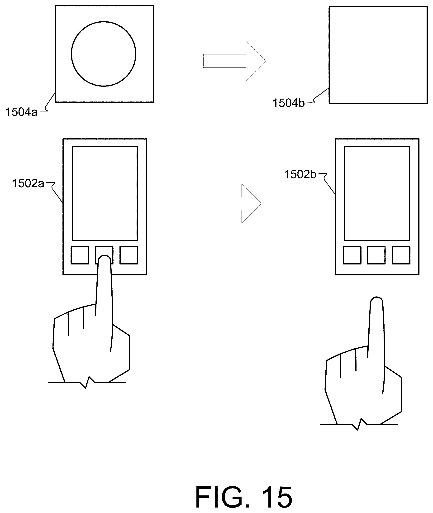
D00013
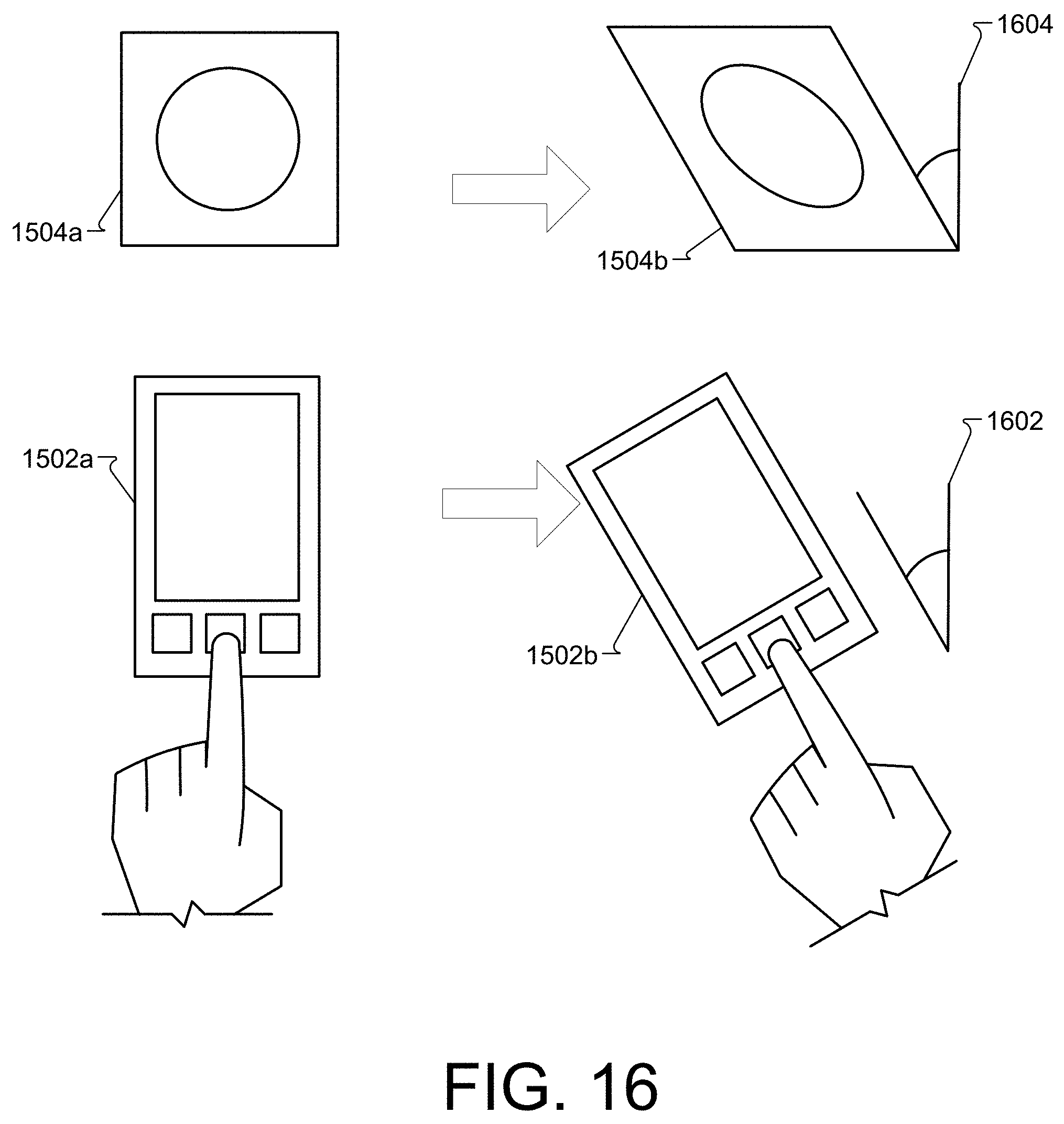
D00014
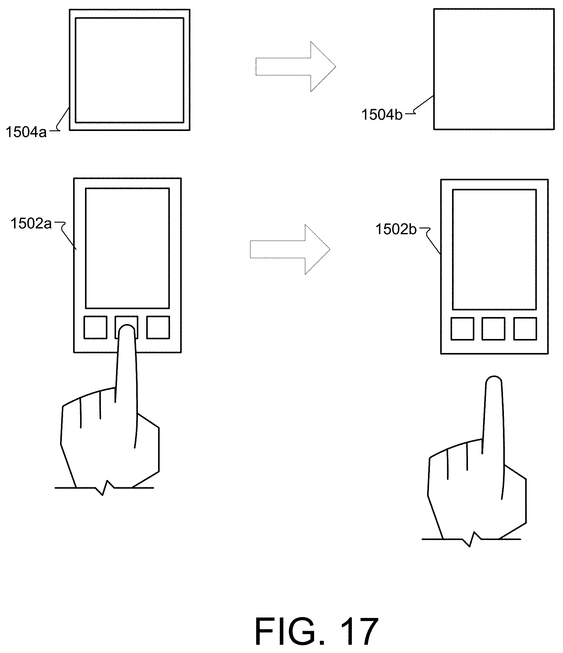
D00015
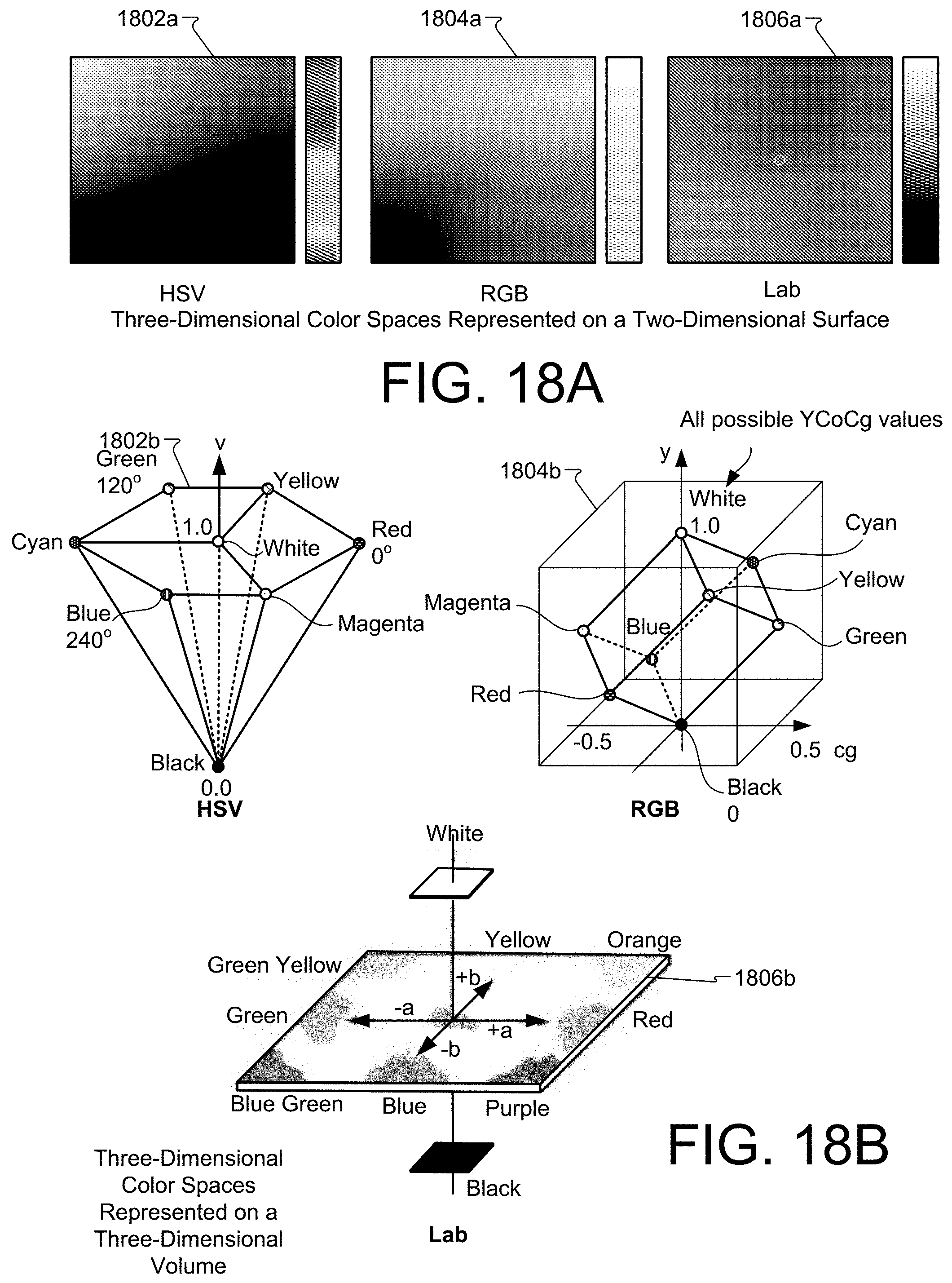
D00016
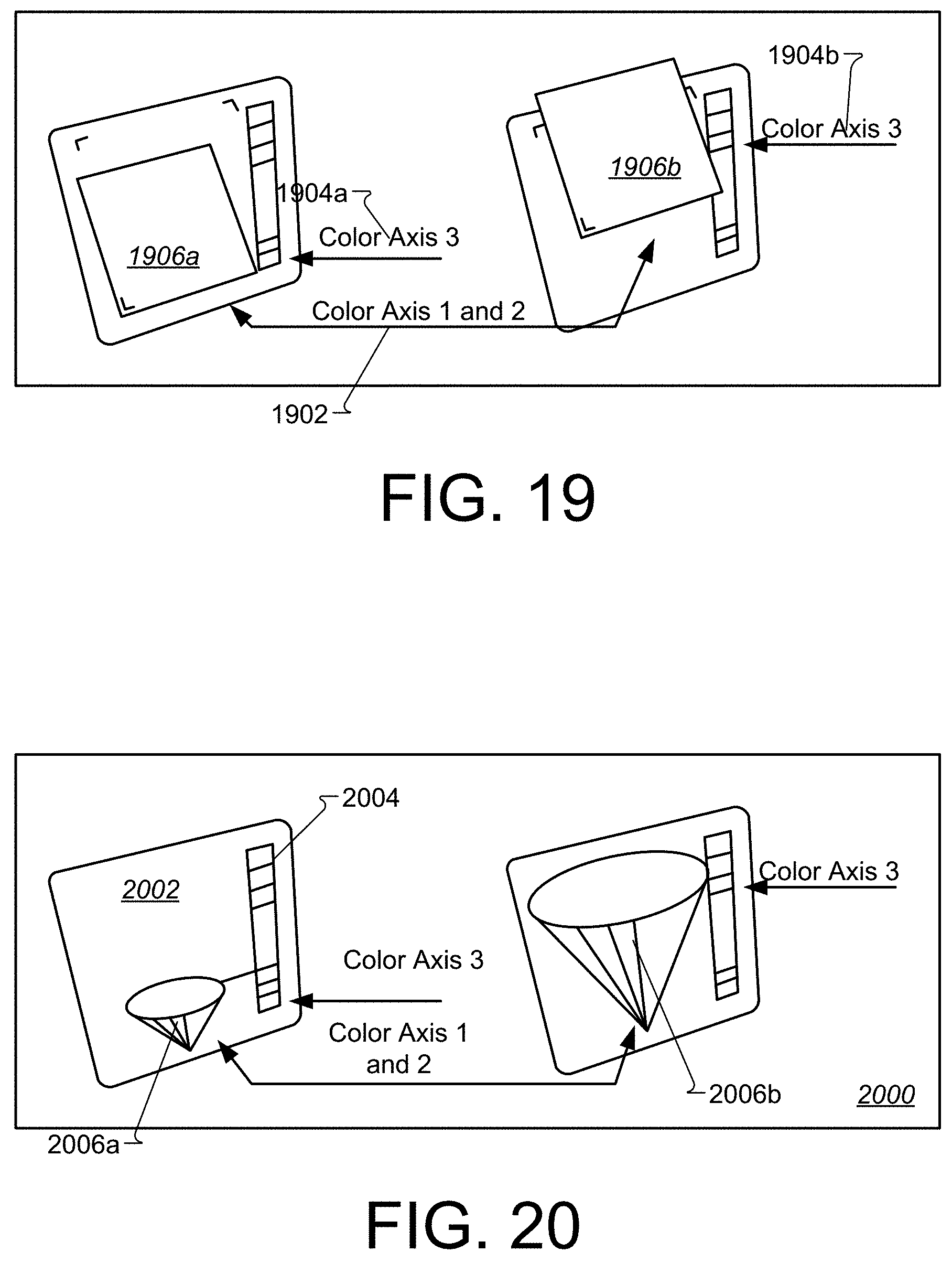
D00017
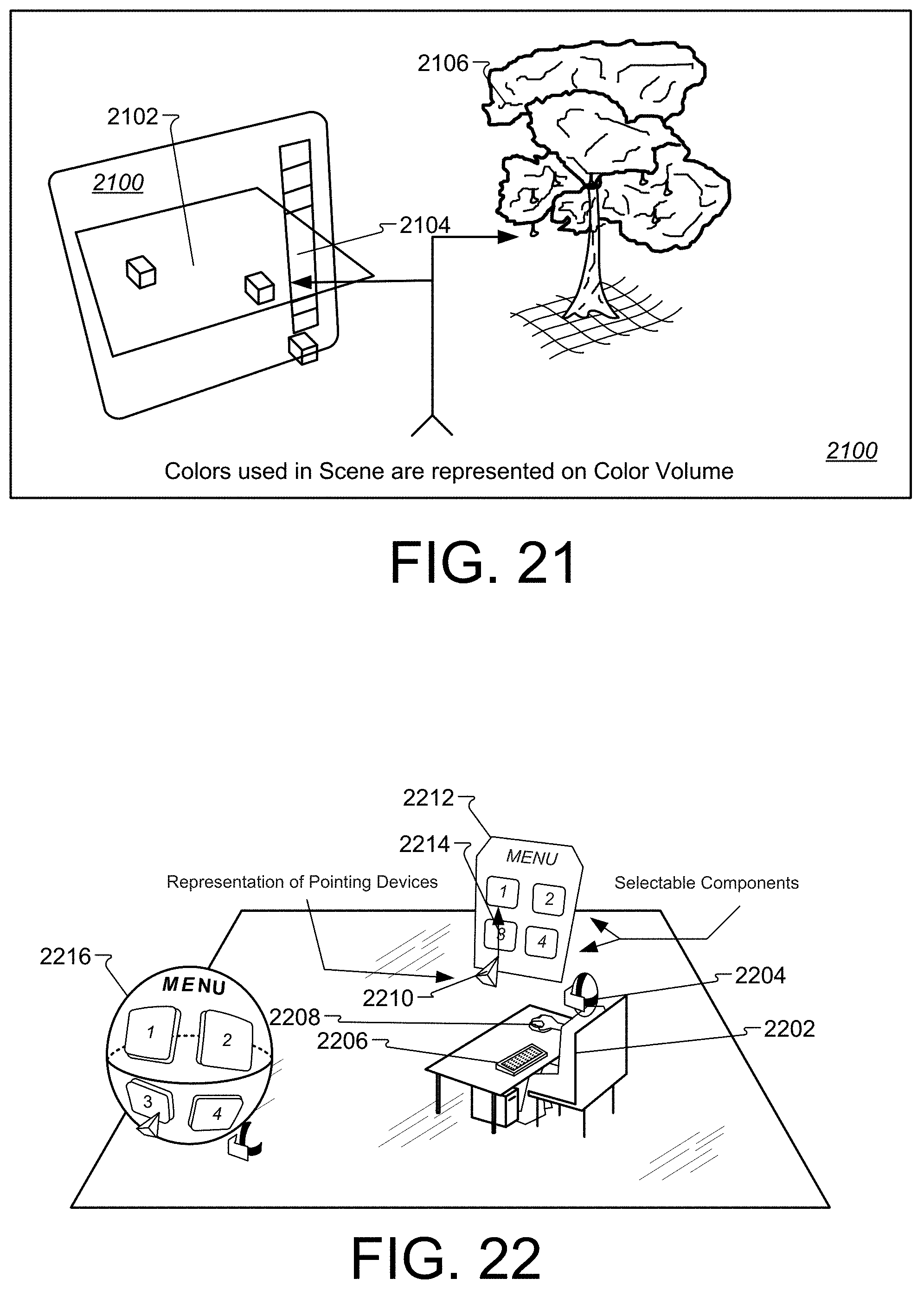
D00018
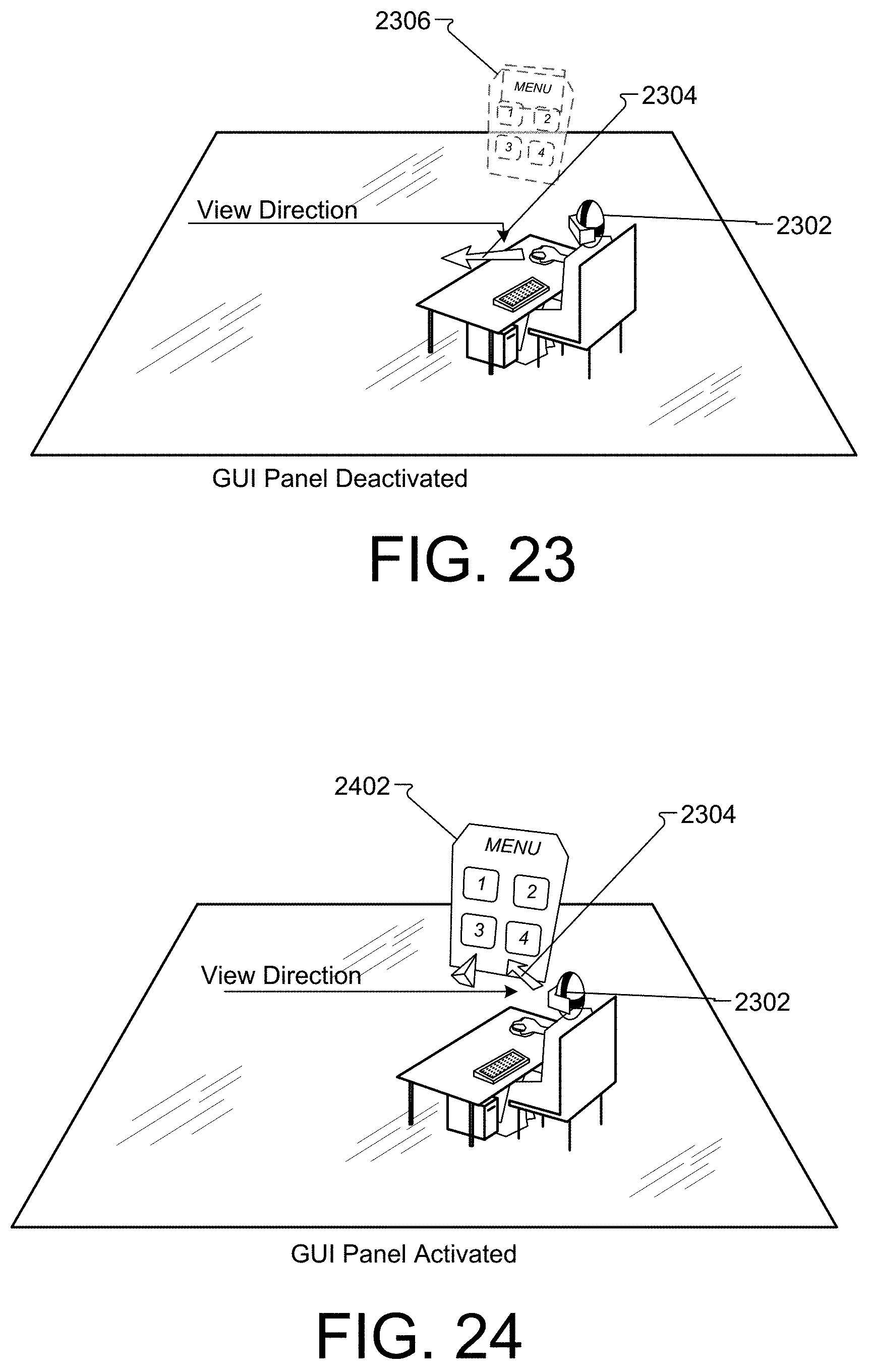
D00019
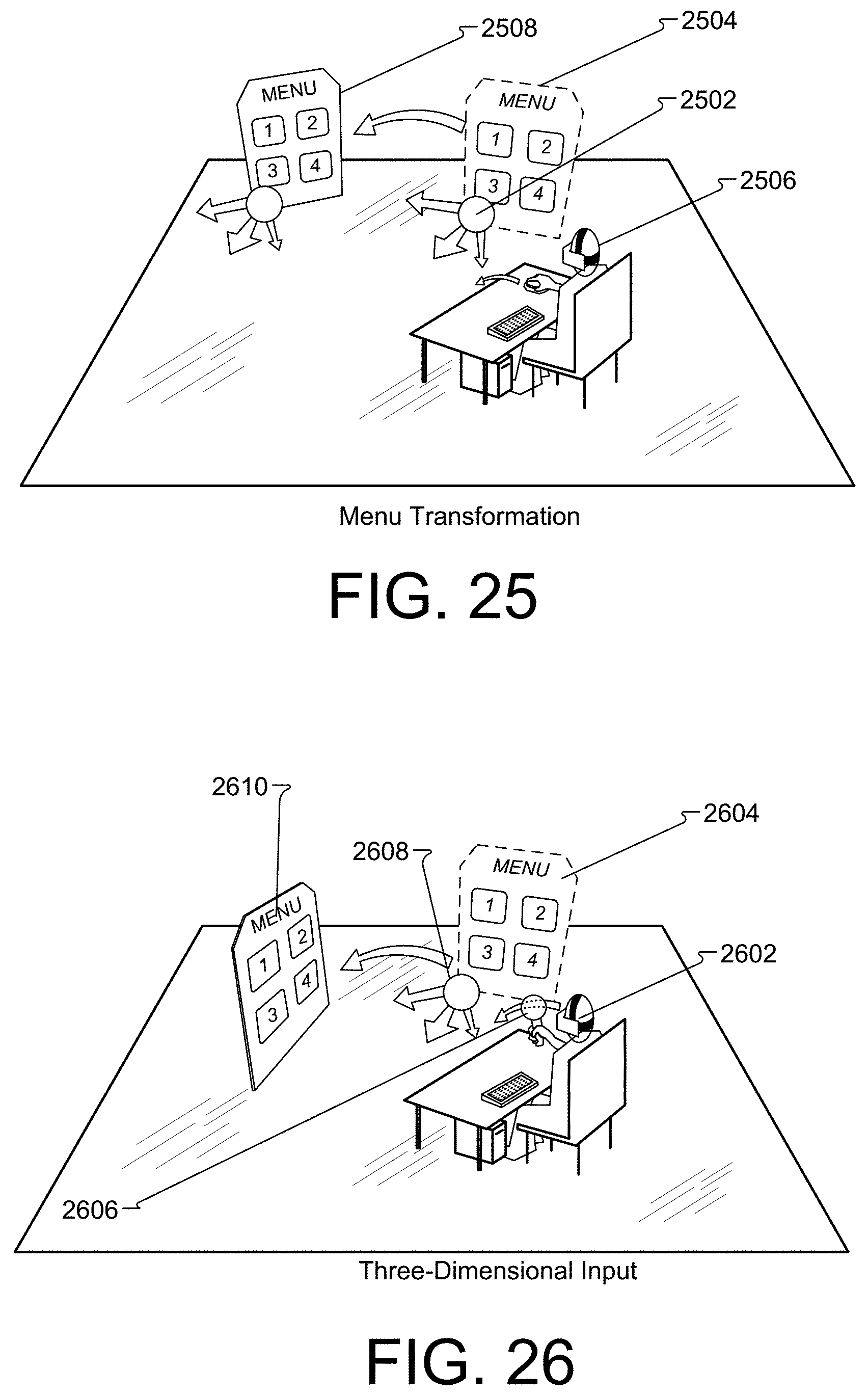
D00020
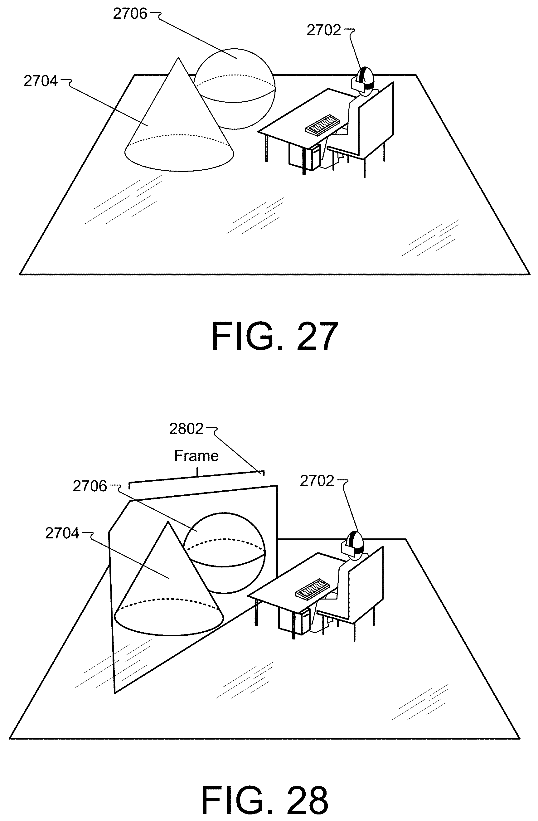
D00021
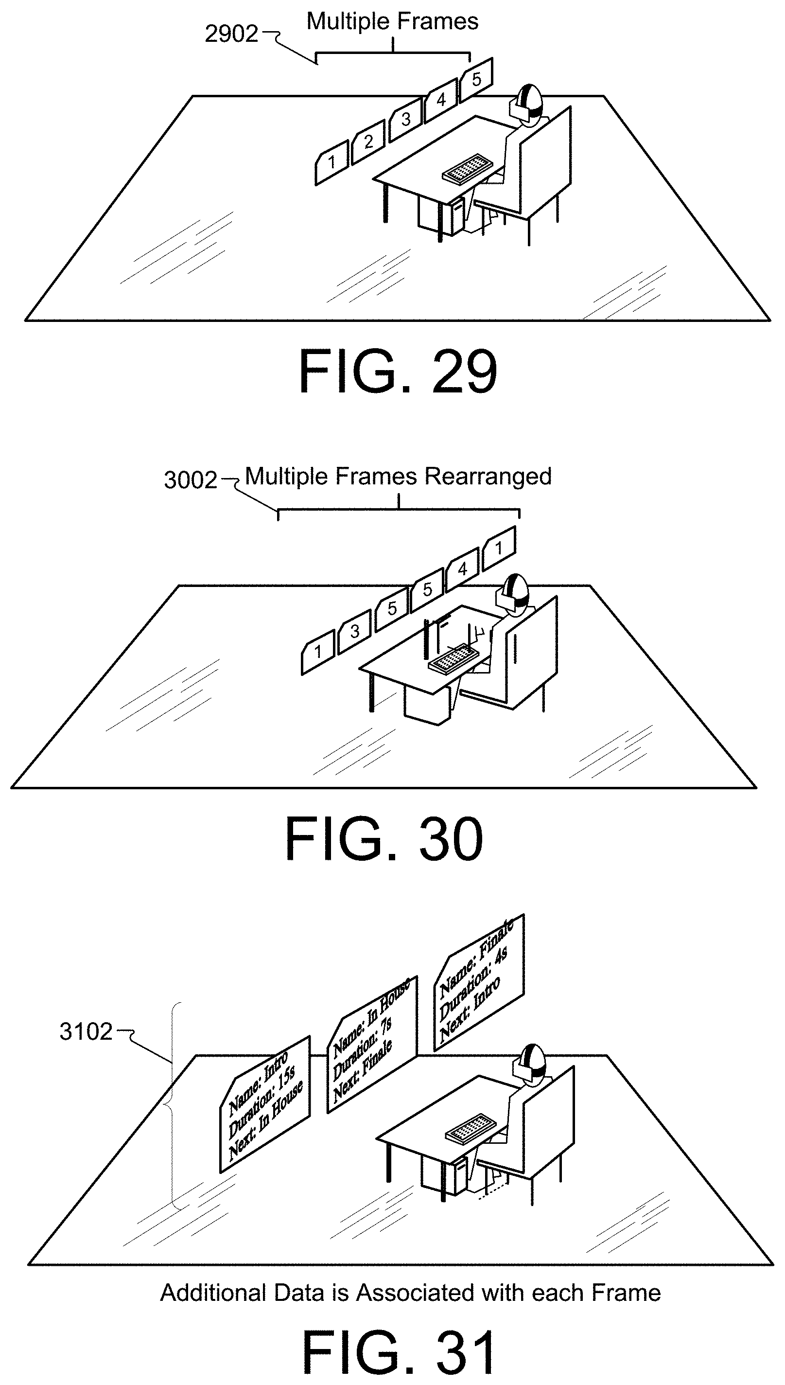
D00022
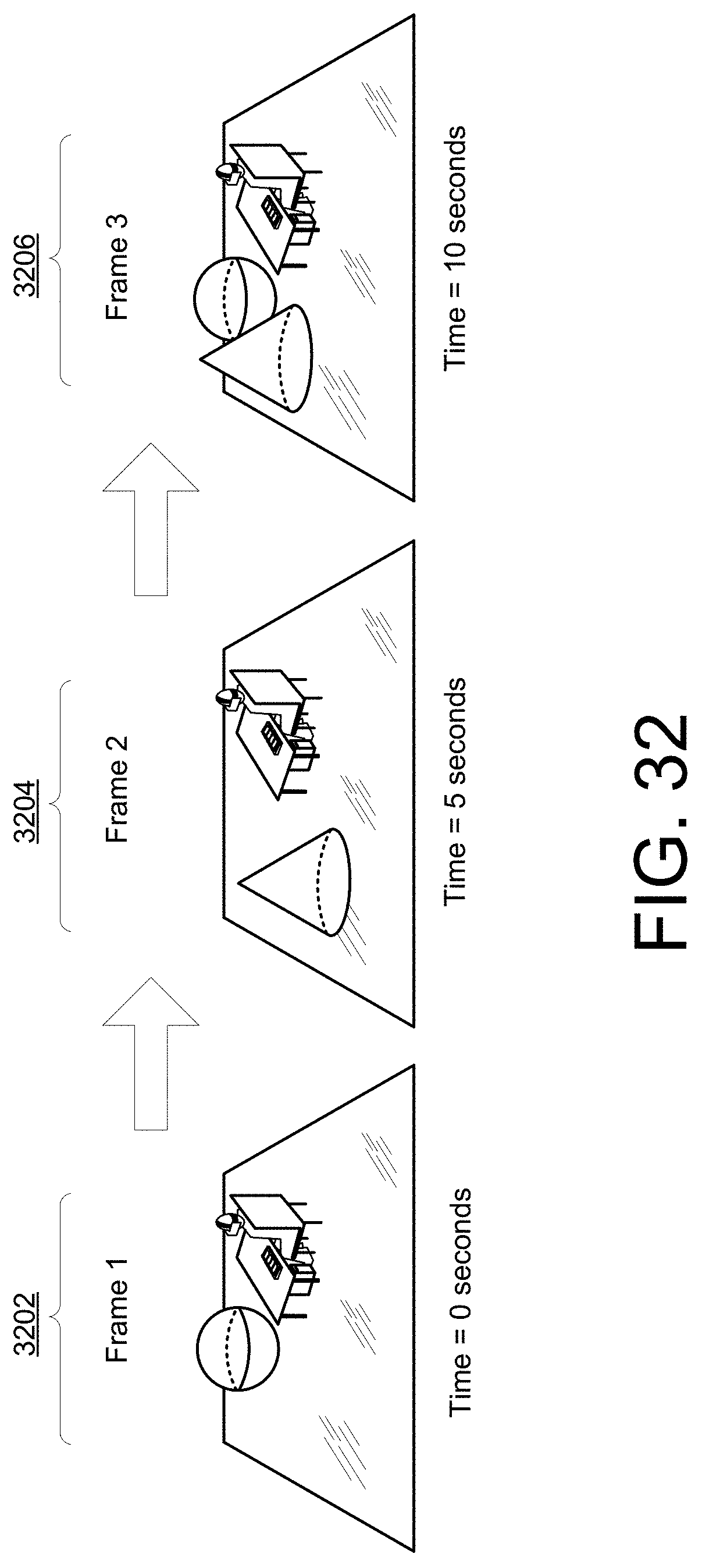
D00023

D00024
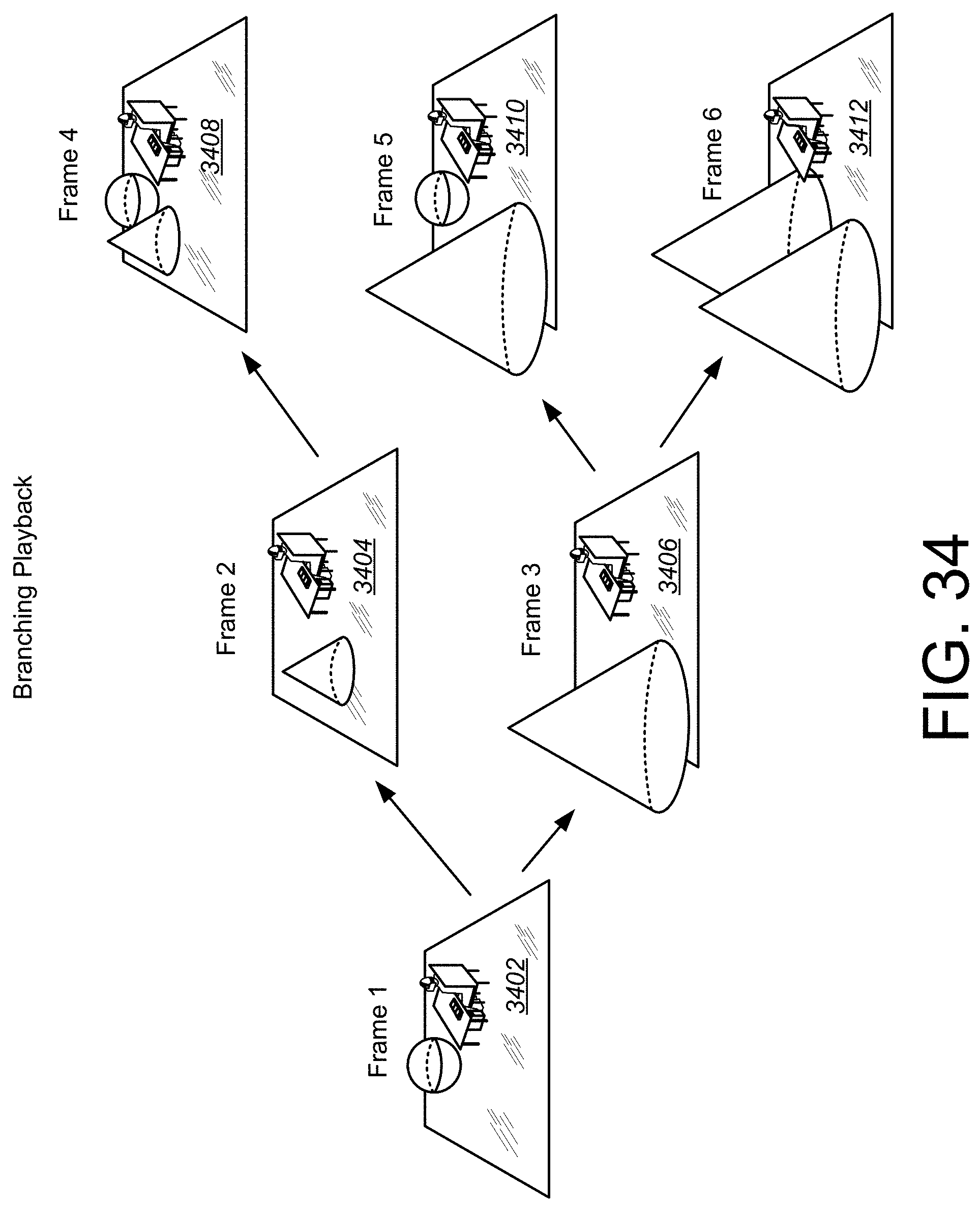
D00025

D00026
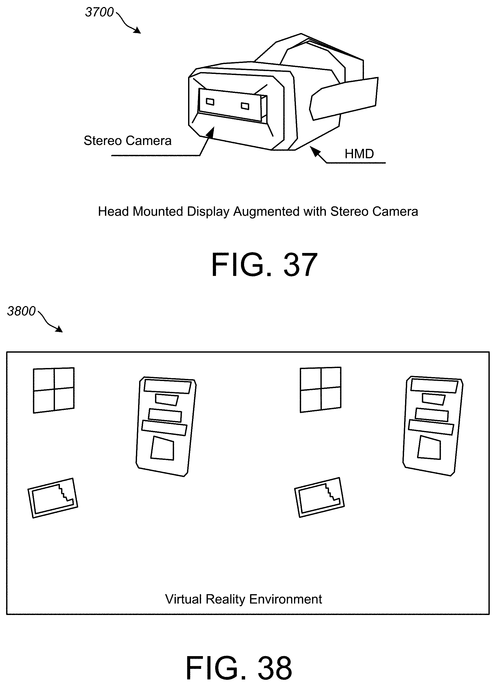
D00027

D00028

D00029
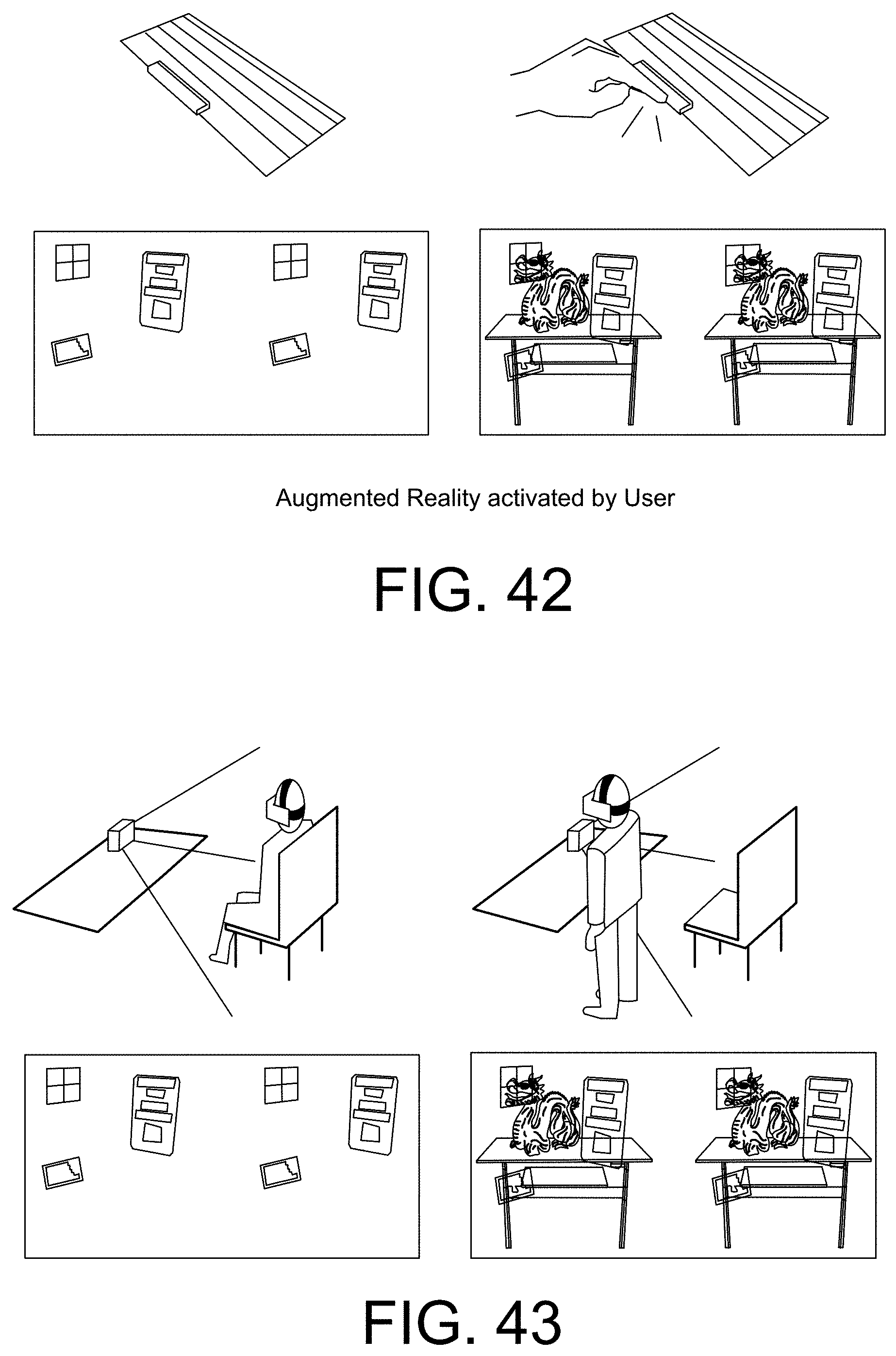
D00030
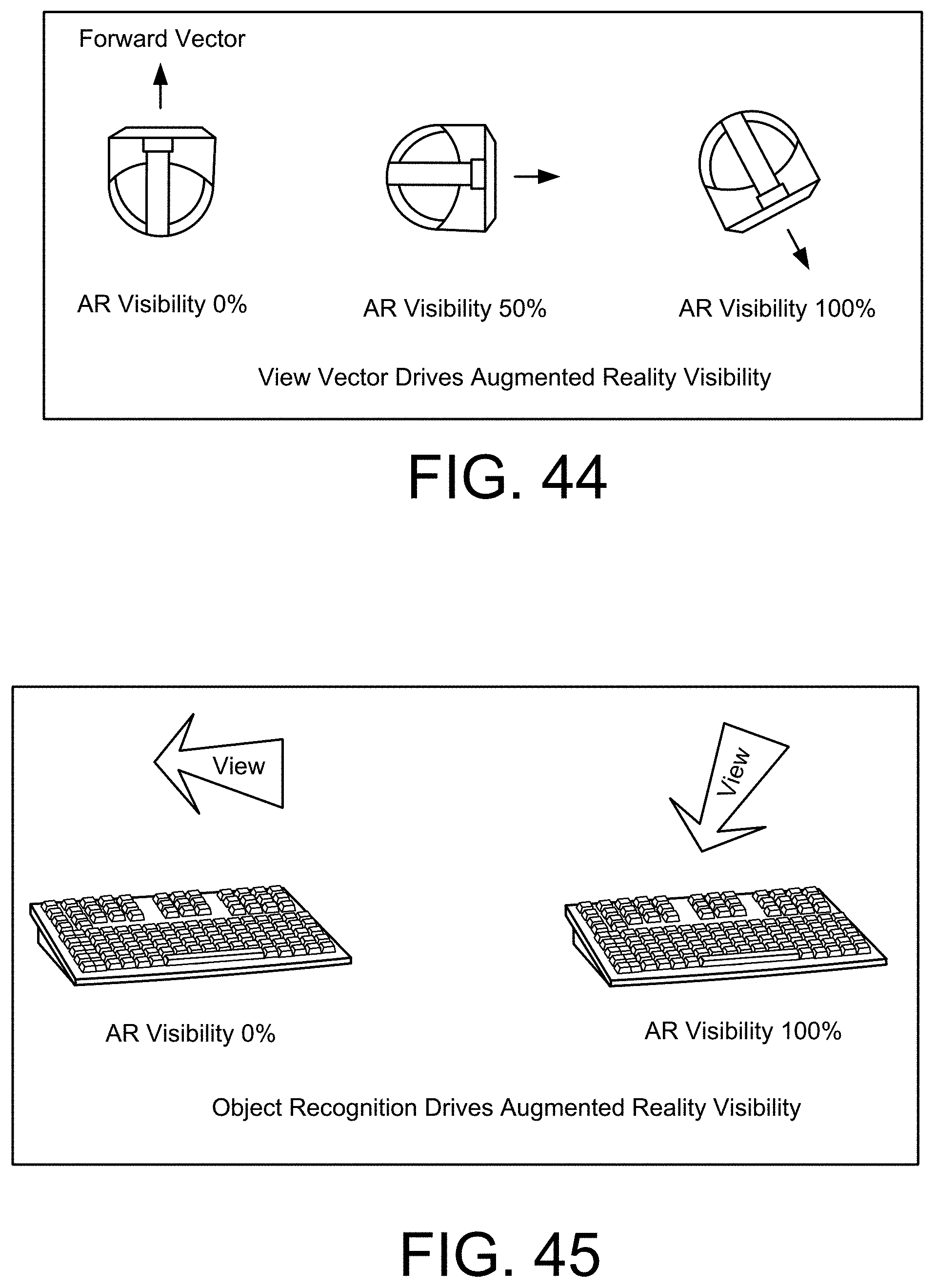
D00031

D00032

D00033
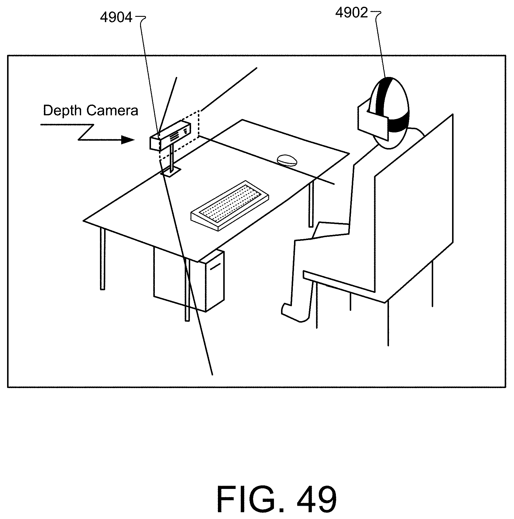
D00034

D00035

D00036

D00037

D00038

D00039

D00040

D00041

D00042
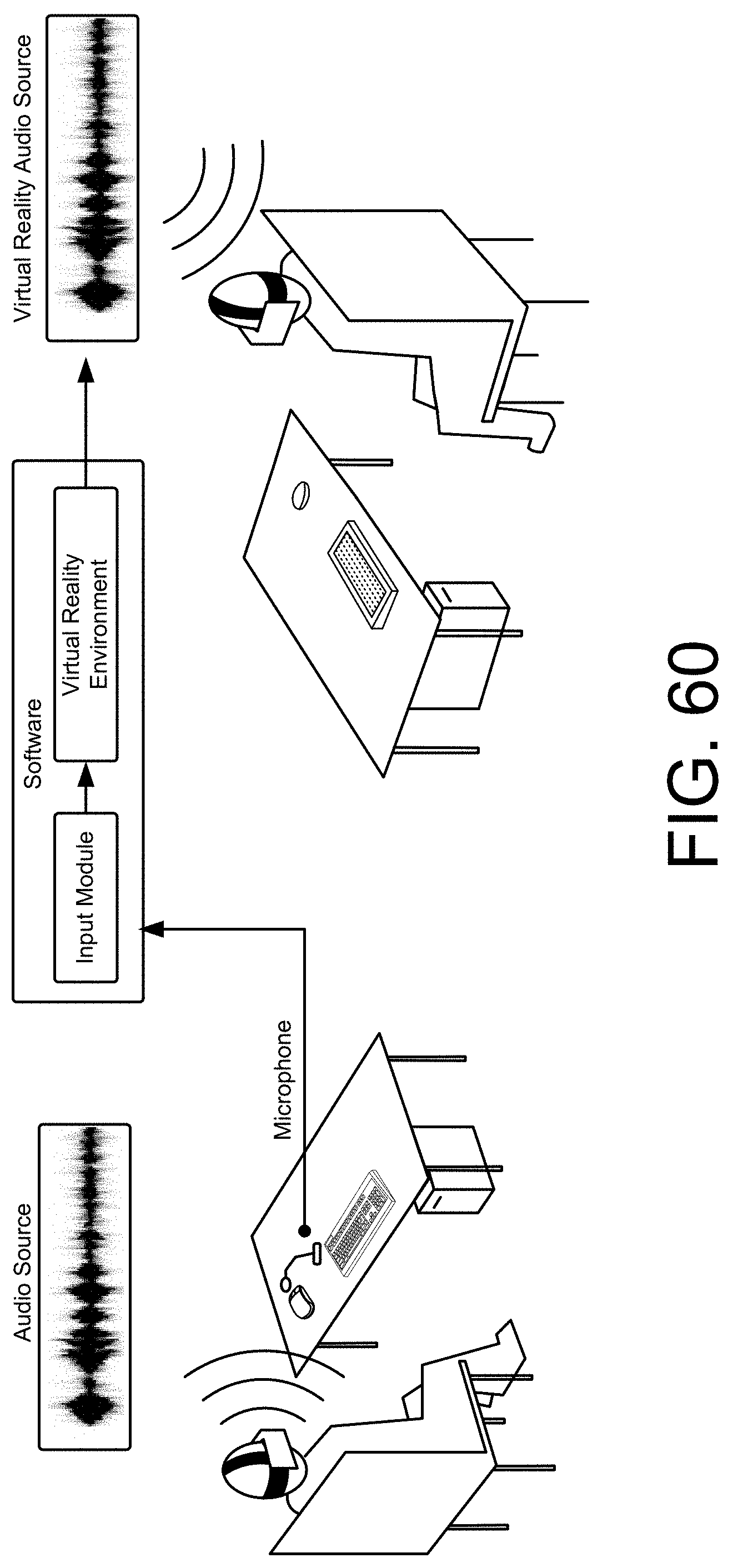
D00043
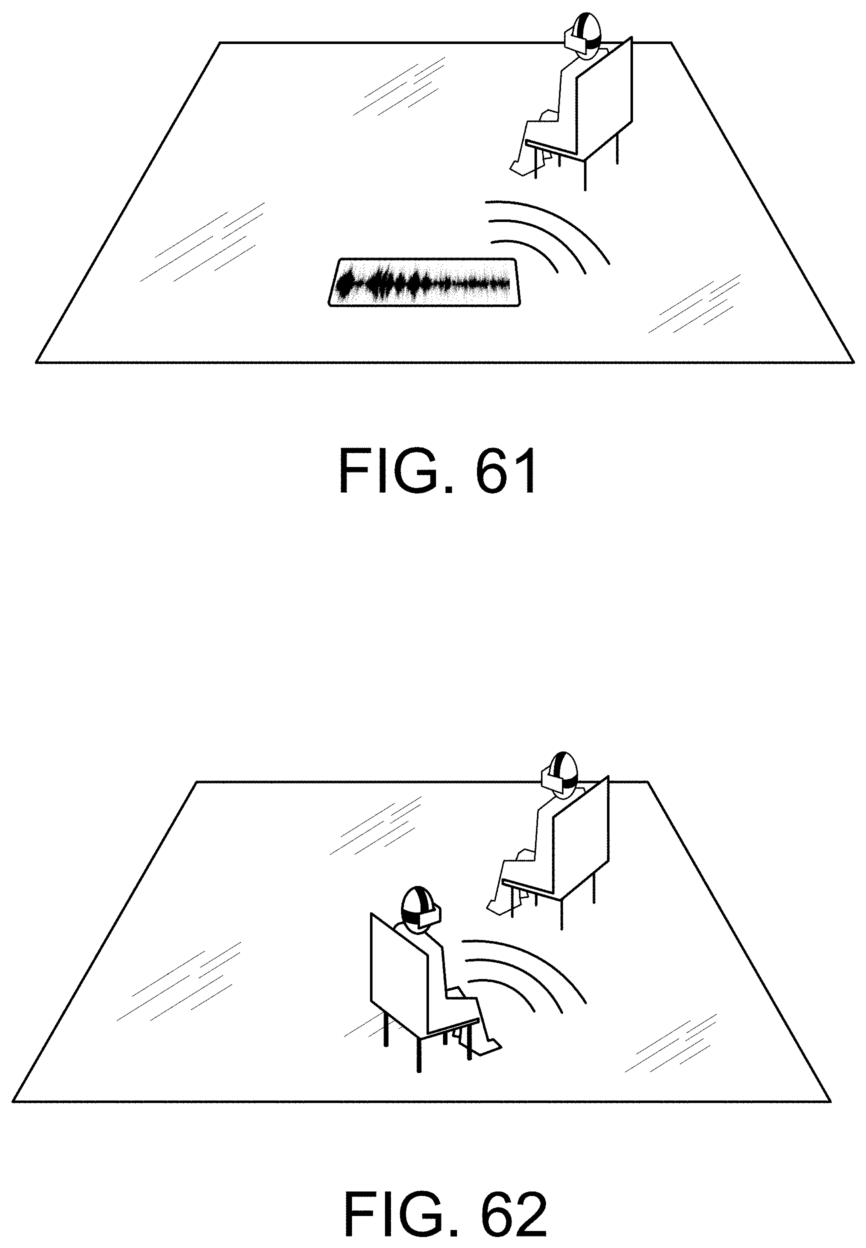
D00044

D00045

D00046
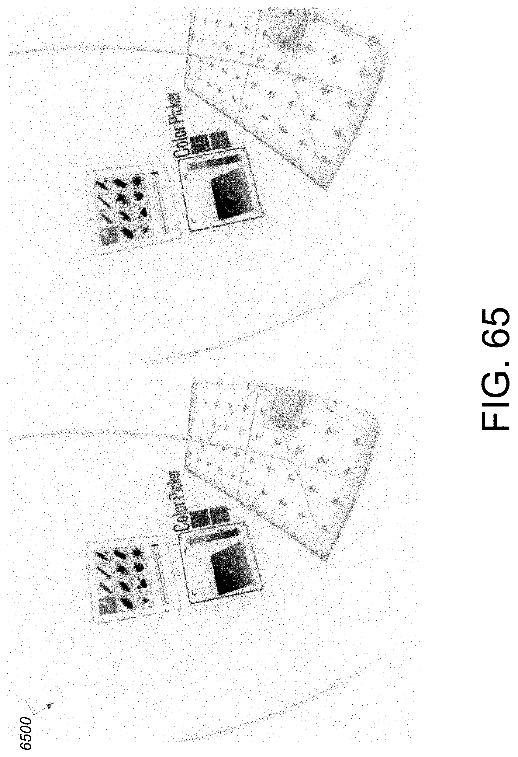
D00047
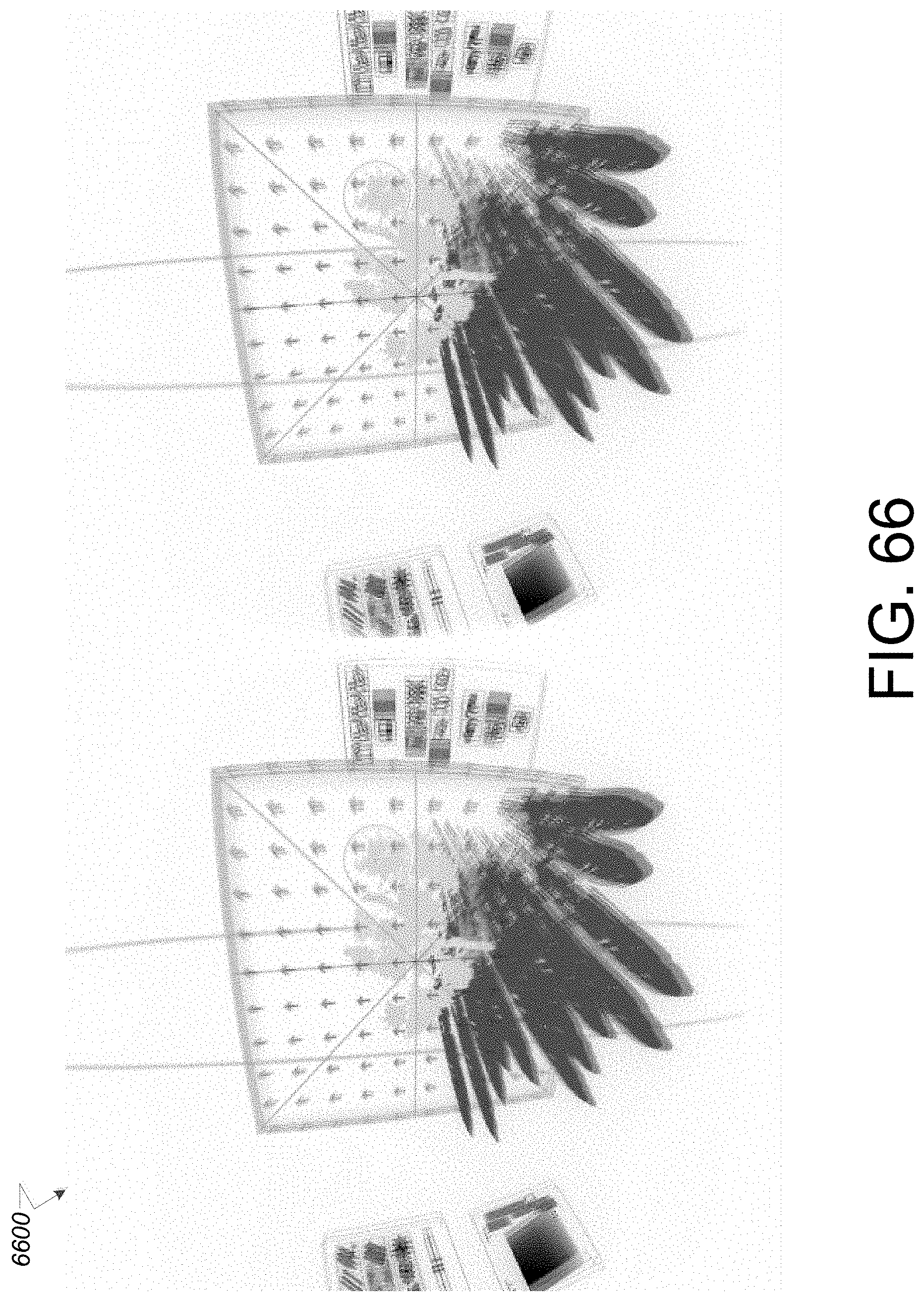
D00048
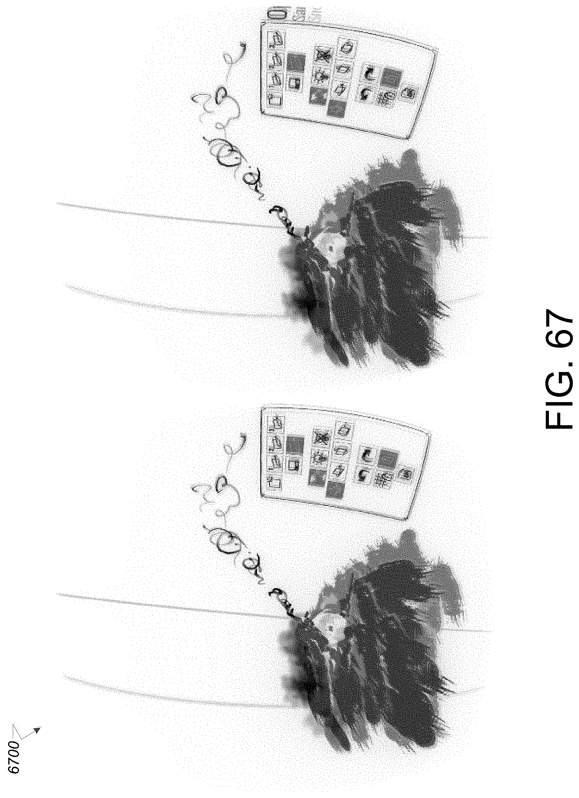
D00049

D00050

D00051
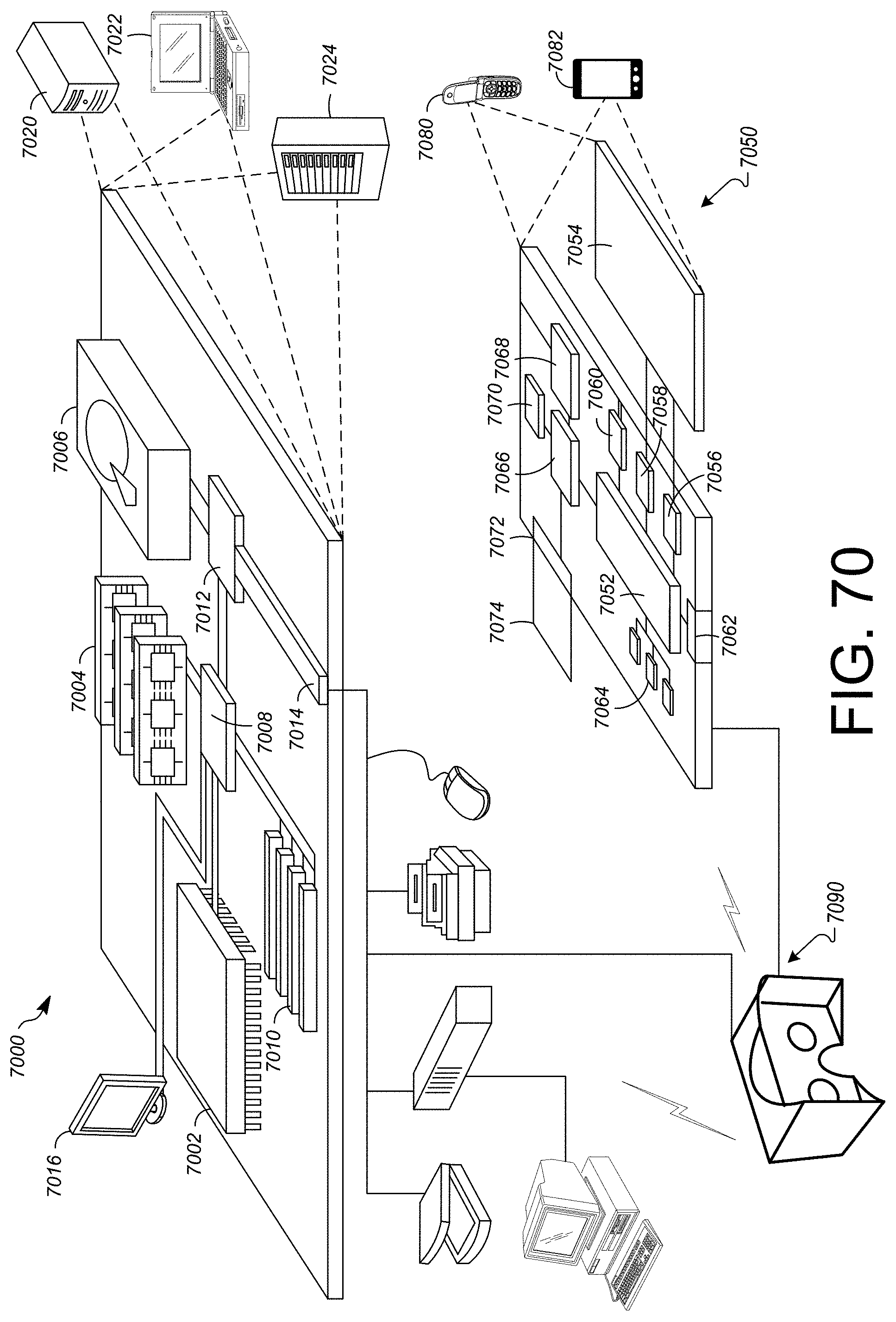
XML
uspto.report is an independent third-party trademark research tool that is not affiliated, endorsed, or sponsored by the United States Patent and Trademark Office (USPTO) or any other governmental organization. The information provided by uspto.report is based on publicly available data at the time of writing and is intended for informational purposes only.
While we strive to provide accurate and up-to-date information, we do not guarantee the accuracy, completeness, reliability, or suitability of the information displayed on this site. The use of this site is at your own risk. Any reliance you place on such information is therefore strictly at your own risk.
All official trademark data, including owner information, should be verified by visiting the official USPTO website at www.uspto.gov. This site is not intended to replace professional legal advice and should not be used as a substitute for consulting with a legal professional who is knowledgeable about trademark law.