Stereoscopic Displays With Addressable Focus Cues
Hua; Hong ; et al.
U.S. patent application number 16/519790 was filed with the patent office on 2019-11-14 for stereoscopic displays with addressable focus cues. The applicant listed for this patent is ARIZONA BOARD OF REGENTS ON BEHALF OF THE UNIVERSITY OF ARIZONA. Invention is credited to Xinda Hu, Hong Hua.
| Application Number | 20190346686 16/519790 |
| Document ID | / |
| Family ID | 50488746 |
| Filed Date | 2019-11-14 |


View All Diagrams
| United States Patent Application | 20190346686 |
| Kind Code | A1 |
| Hua; Hong ; et al. | November 14, 2019 |
STEREOSCOPIC DISPLAYS WITH ADDRESSABLE FOCUS CUES
Abstract
The present invention relates generally to stereoscopic displays, and more particularly, but not exclusively, to stereoscopic displays with addressable focus cues.
| Inventors: | Hua; Hong; (Tucson, AZ) ; Hu; Xinda; (Sunnyvale, CA) | ||||||||||
| Applicant: |
|
||||||||||
|---|---|---|---|---|---|---|---|---|---|---|---|
| Family ID: | 50488746 | ||||||||||
| Appl. No.: | 16/519790 | ||||||||||
| Filed: | July 23, 2019 |
Related U.S. Patent Documents
| Application Number | Filing Date | Patent Number | ||
|---|---|---|---|---|
| 15833387 | Dec 6, 2017 | 10394036 | ||
| 16519790 | ||||
| 14435328 | Apr 13, 2015 | 9874760 | ||
| PCT/US2013/065422 | Oct 17, 2013 | |||
| 15833387 | ||||
| 61795500 | Oct 18, 2012 | |||
| Current U.S. Class: | 1/1 |
| Current CPC Class: | G02B 2027/0134 20130101; G02B 27/106 20130101; G02B 17/086 20130101; G02B 2027/0132 20130101; G02B 27/0172 20130101; G02B 27/0101 20130101; H04N 13/344 20180501; H04N 13/339 20180501; G02B 30/00 20200101; G02B 2027/011 20130101 |
| International Class: | G02B 27/22 20060101 G02B027/22; H04N 13/344 20060101 H04N013/344; G02B 27/01 20060101 G02B027/01; G02B 17/08 20060101 G02B017/08; G02B 27/10 20060101 G02B027/10; H04N 13/339 20060101 H04N013/339 |
Goverment Interests
GOVERNMENT LICENSE RIGHTS
[0002] This invention was made with government support under IIS0915035 awarded by NSF. The government has certain rights in the invention.
Claims
1. A virtual display system with addressable focus cues, comprising: a microdisplay for providing a virtual image for display to a user; a reflective active optical element configured to provide a variable optical power; and a see-through eyepiece, with focal length f.sub.eye, comprising a selected surface configured to receive optical radiation from the reflective active optical element and reflect the received radiation to an exit pupil of the system to provide a virtual display path which relays a stop of the virtual display system defined by the reflective active optical element therewith to form the exit pupil, and wherein the selected surface is also configured to receive optical radiation from a source other than the microdisplay and to transmit such optical radiation to the exit pupil to provide a see-through optical path, wherein the ratio of the size of the exit pupil, D.sub.xp, to the size of the reflective active optical element, D.sub.DMMD, is D XP = D DMMD f 1 / f eye . ##EQU00008##
2. The display system of claim 1, wherein the eyepiece comprises a freeform prism shape.
3. The display system of claim 1, wherein the eyepiece comprises a first surface configured to receive and refract optical radiation from the reflective active optical element and comprises a second surface configured to receive the refracted optical radiation from the first surface, the second surface configured to reflect the optical radiation to the selected surface of the eyepiece.
4. The display system of claim 3, wherein the second surface is configured to total internally reflect the optical radiation.
5. The display system of claim 1, wherein one or more of the surfaces of the eyepiece comprise a rotationally asymmetric surface.
6. The display system of claim 1, comprising an eyepiece compensator disposed along the see-through path adjacent the selected surface of the eyepiece.
7. The display system of claim 1, comprising a field lens disposed adjacent the microdisplay configured to provide magnification of the display.
8. The display system of claim 7, wherein the field lens comprises an aspheric surface and a diffractive optical feature.
Description
RELATED APPLICATIONS
[0001] This present application is a continuation application of U.S. application Ser. No. 15/833,387 file on Dec. 6, 2017, which is a divisional application of U.S. application Ser. No. 14/435,328 file on Apr. 13, 2015, which is a 371 application of International Application No. PCT/US2013/065422 filed Oct. 17, 2013, which claims the benefit of priority of U.S. Provisional Application No. 61/795,500, filed on Oct. 18, 2012, the entire contents of which application(s) are incorporated herein by reference.
FIELD OF THE INVENTION
[0003] The present invention relates generally to stereoscopic displays, and more particularly, but not exclusively, to stereoscopic displays with addressable focus cues.
BACKGROUND OF THE INVENTION
[0004] Conventional stereoscopic 3D displays create the illusion of depth based on binocular disparities, rendering 3D scenes from a single pair of 2D perspective images at a fixed distance to the viewer. Therefore conventional stereoscopic displays force an unnatural decoupling of the accommodation and convergence cues, which may contribute to various visual artifacts in stereoscopic displays, such as distortion in perceived depth, diplopic vision, visual discomfort, and fatigue. Many approaches have been proposed which may overcome the drawbacks of conventional stereoscopic displays, including volumetric displays, holographic displays, and multi-focal-plane displays. However, a need exists to develop an optical see-through stereoscopic display which solves the fundamental accommodation-convergence problems and also renders large volumes of continuous 3D scene at high image quality and flickering-free speed.
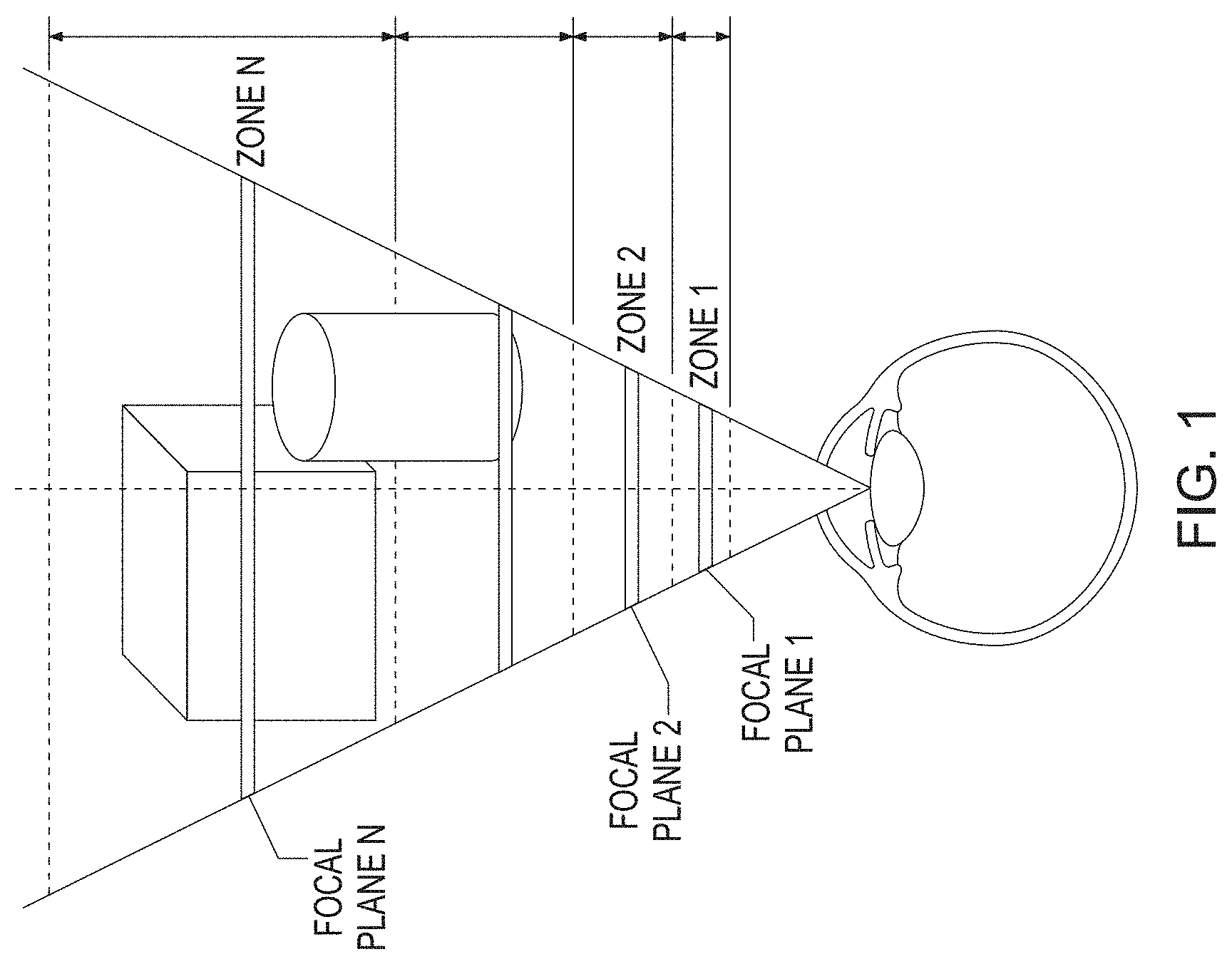
[0005] A stereoscopic display with addressable focus cues is one of the most promising approaches to solving the fundamental accommodation-convergence problems of providing the capability of rendering correct or near-correct focus cues for virtual 3D objects. Unlike traditional stereoscopic displays, stereoscopic displays with addressable focus cues enable the ability to either dynamically vary the focal distance of the virtual display through an active optical element in accordance to the viewer's region of interest, known as vari-focal display mode, or present multiple focal planes at a flickering-free speed through with no need to track a viewer's region of interest, known as multi-focal display mode. For instance, multi-focal-plane displays present perspective 2D images at multiple carefully placed, discrete focal distances along the visual axis. These discrete focal planes sample a 3D scene volume into multiple zones, and objects within a zone are rendered by the corresponding pair of adjacent focal planes, as shown in FIG. 1. Therefore multi-focal-plane displays are able to render correct or near-correct focus cues for virtual objects at different depths. Contrary to multi-viewpoint displays such as holographic displays and volumetric displays, the multi-focal-plane display is a fixed-viewpoint display. By restricting the viewing position, multi-focal-plane display systems only need to display a small number of viewpoints. Also multi-focal-point displays can preserve disparity, occlusion and perspective in conventional 2D displays as well as rendering viewing-dependent lighting effects such as specular reflection and shading. In practice, the implementations of multi-focal-plane displays can be categorized into two categories: spatially multiplexed or temporally multiplexed. In a spatial-multiplexed system, multi-focal capability is achieved by stacking multiple 2D displays. In the alternative and more elegant, time-multiplexed system, the focal distances of images from a single 2D display are fast switched by an active optical element in synchronization with the frame rendering of multiple focal planes. In general, a multi-focal plane display can be readily adapted for use in a vari-focal mode without much change to the optics layout.
[0006] In addition, progress has recently been made in the field of stereoscopic displays that can be head-mounted and that have addressable focal planes for improved depth perception but require substantially less computational power than existing methods, as reflected in commonly owned U.S. Patent Application Publication. No. 2011/0075257, the contents of which are incorporated herein by reference. However, a need still exists for optical imaging systems which can provide enhanced imaging performance in stereoscopic displays with addressable focus cues.
SUMMARY OF THE INVENTION
[0007] In one of its aspects, the present invention may provide a virtual display system with addressable focus cues comprising a microdisplay for providing a virtual image for display to a user. A reflective active optical element, configured to provide a variable optical power, may also be provided. A relay lens may be disposed along an optical path between the microdisplay and the active optical element, with the relay lens positioned therebetween such that the microdisplay and active optical element are disposed at conjugate planes of the relay lens. A beamsplitter may be disposed along the optical path between the microdisplay and the active optical element at an orientation to receive optical radiation from the active optical element. In addition, a see-through eyepiece may be provided which includes a selected surface configured to receive optical radiation from the beamsplitter and reflect the received radiation to an exit pupil of the system to provide a virtual display path. The selected surface may also be configured to receive optical radiation from a source other than the microdisplay (such as the real world) and to transmit such optical radiation to the exit pupil to provide a see-through optical path. The eyepiece may include a freeform prism shape, and, in particular, may include a first surface configured to receive and refract optical radiation from the beamsplitter and may include a second surface configured to receive the refracted optical radiation from the first surface, with the second surface configured to reflect the optical radiation to the selected surface of the eyepiece. The second surface may be configured to total internally reflect the optical radiation, and one or more of the surfaces of the eyepiece may comprise a rotationally asymmetric surface.
[0008] In another of its aspects, the present invention may provide a virtual display system with addressable focus cues comprising a microdisplay for providing a virtual image for display to a user, and an eyepiece comprising a reflective optical element configured to reflect optical radiation from the microdisplay to an exit pupil of the system. A relay lens, comprising a refractive active optical element configured to provide a variable optical power, may be disposed along an optical path between the microdisplay and the eyepiece to relay an image from the microdisplay to the eyepiece. The relay lens may include first and second lens groups disposed along the optical path with the active optical element located between the first and second lens groups. In addition, a beamsplitter may be disposed along the optical path between the microdisplay and the eyepiece, with the beamsplitter configured to receive and transmit optical radiation from a source other than the microdisplay (such as the real world) to the exit pupil to provide a see-through optical path. The eyepiece may comprise a spherical mirror, and the system may be telecentric in the microdisplay. The system may also have an f-number less than 3.
BRIEF DESCRIPTION OF THE DRAWINGS
[0009] The foregoing summary and the following detailed description of exemplary embodiments of the present invention may be further understood when read in conjunction with the appended drawings, in which:
[0010] FIG. 1 schematically illustrates 3D objects rendered by multiple focal planes relative to a viewer;
[0011] FIG. 2 schematically illustrates the unfolded optical path of an exemplary display system in accordance with the present invention;
[0012] FIG. 3A schematically illustrates a 2D layout of virtual display optics of an exemplary display system in accordance with the present invention;
[0013] FIG. 3B schematically illustrates a 2D layout of the exemplary display system of FIG. 3A but having a field lens comprising two optical elements rather than a singlet;
[0014] FIG. 3C schematically illustrates the free-form eyepiece and compensator of FIGS. 3A-3B showing the see-through optical path;
[0015] FIG. 3D schematically illustrates the free-form eyepiece and compensator of FIGS. 3A-3B showing both the see-through and display paths;
[0016] FIGS. 4A-4E illustrate the polychromatic MTF through the display path for the virtual display system of FIG. 3B;
[0017] FIG. 4F illustrates a distortion grid through the display path for the virtual display system of FIG. 3B;
[0018] FIGS. 5A-5E illustrate the polychromatic MTF through the see-through path for the virtual display system of FIG. 3B;
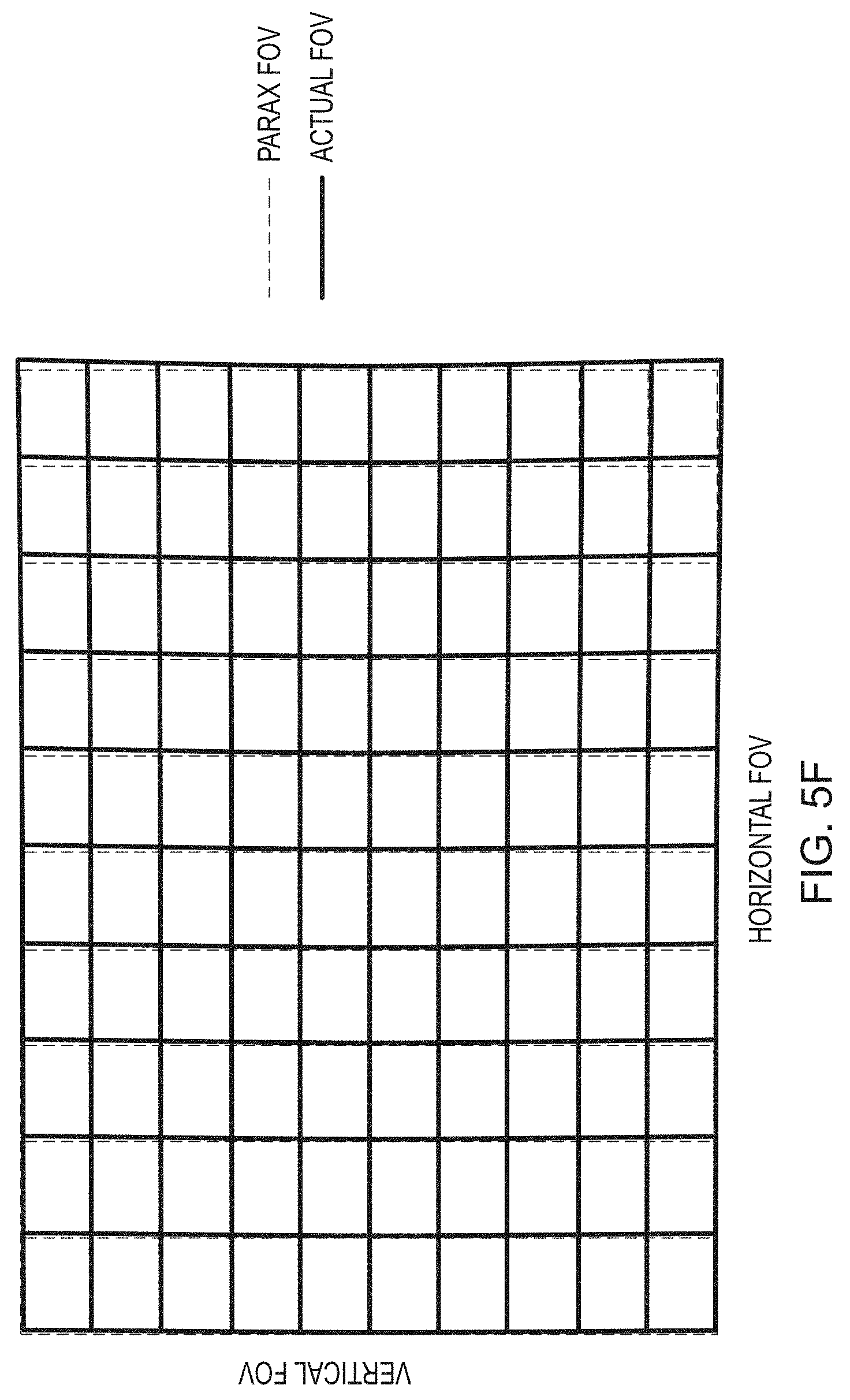
[0019] FIG. 5F illustrates a distortion grid through the see-through path for the virtual display system of FIG. 3B;
[0020] FIG. 6A schematically illustrates a 3D layout of the free-form eyepiece with relay optics of the display system of FIG. 3B;
[0021] FIG. 6B schematically illustrates a 3D Solidworks model of the assembled free-form eyepiece and compensator of the display system of FIG. 6A;
[0022] FIG. 7A illustrates a depth-fused 6-focal-plane 3D scene of 40 degrees of field of view and 3 diopters of depth, captured through the eyepiece for a prototype built according to the design of FIG. 3B;
[0023] FIGS. 7B-7C illustrate 6-focal-plane 3D scenes captured by a camera focused at 2 m and 30 cm, respectively, for a prototype built according to the design of FIG. 3B;
[0024] FIG. 8A illustrates a retinal image MTF as a function of accommodations in a dual-focal-plane display, with two focal planes placed at 1.2D and 1.8D, respectively, and with a luminance ratio of 1:1;
[0025] FIG. 8B illustrates a retinal image contrast as a function of accommodation showing the contrast gradient for different spatial frequencies;
[0026] FIGS. 9A-9B illustrate that the spatial frequency of a transition point decreases when the focal plane separation increases and when the eye pupil size increases, respectively;
[0027] FIGS. 10A, 10B schematically illustrate 2D and 3D layouts, respectively, of the virtual display optics of a further exemplary display system in accordance with the present invention;
[0028] FIG. 11 schematically illustrates a 2D layout and element descriptions of the relay lens group of FIG. 10A along with an optional display illumination path; and
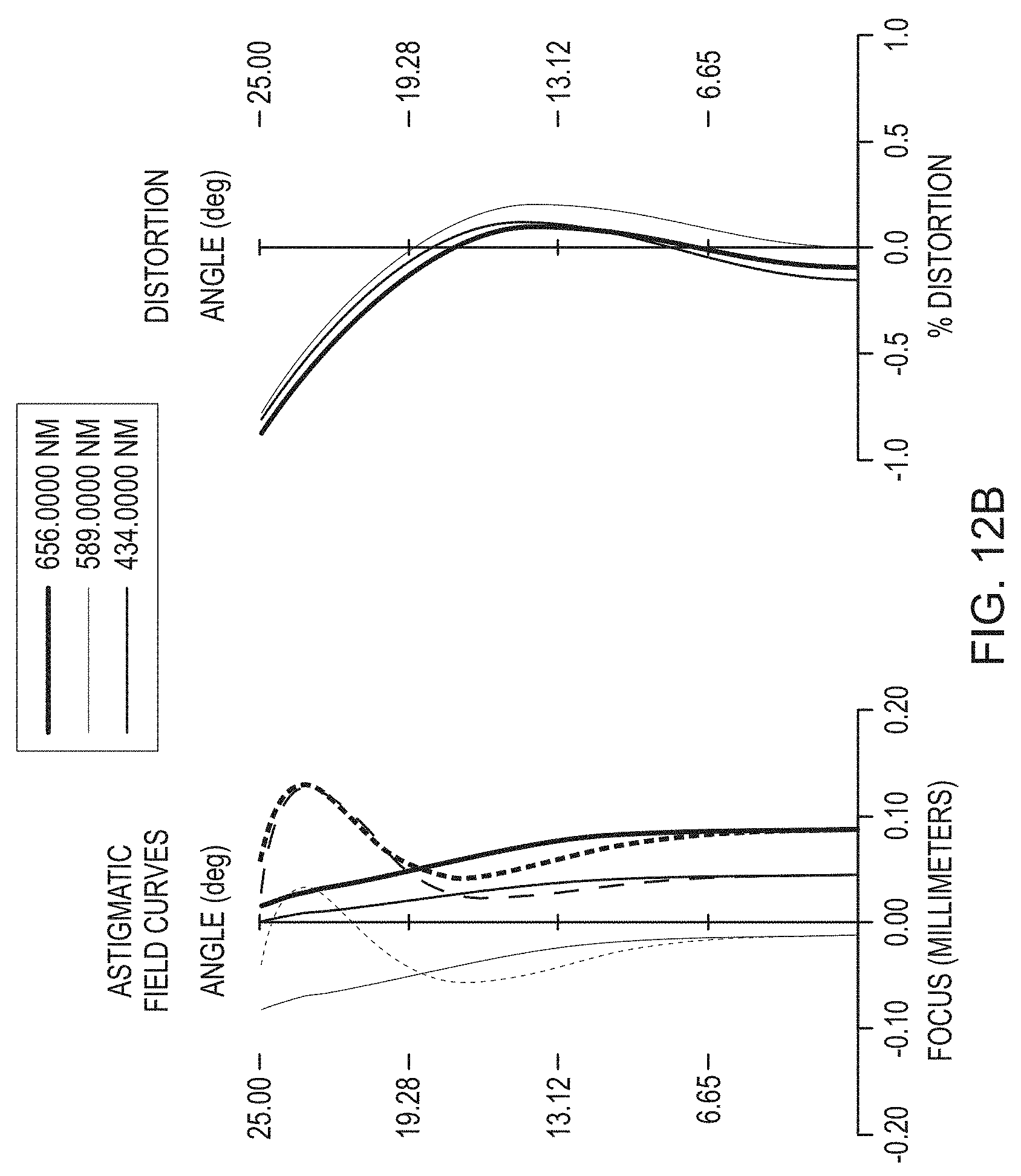
[0029] FIGS. 12A, 12B illustrate polychromatic MTF and field curves, respectively, of the system of FIGS. 10A-11.
DETAILED DESCRIPTION OF THE INVENTION
[0030] Referring now to the figures, wherein like elements are numbered alike throughout, in accordance with one aspect of the present invention, FIG. 2 schematically illustrates the first-order unfolded optical path of an exemplary optical system which is particularly suited for providing high imaging quality in depth-fused multi-focal-plane stereoscopic displays with addressable focus cues. FIGS. 3A, 3B schematically illustrate particular designs according to the layout of FIG. 2, with a first optical system 100 having a single field lens 18, FIG. 3A, and an alternative system 200 having a two-element 17, 19 field lens 18, FIG. 3B. (While a single set of optics for a single viewer's eye is illustrated, it is understood that in a final stereoscopic device, two such sets of optics will be provided, one for each eye.)
[0031] A relevant feature of the designs is the inclusion of a relay lens group 20 which relays the image from a microdisplay, such as a digital micro-mirror device (DMD) 60, to the front of an eyepiece 12. The relay lens group 20 may include a traditional, non-deformable lens 21 and a reflective active optical element, such as a deformable membrane mirror 80, FIG. 2. The relay lens 21 may include a pair of doublets 22, 24 and lens 26, FIGS. 3A, 3B. The deformable membrane mirror device (DMMD) 80 may be placed at the focal plane of the relay lens 21 and may serve as the system stop. Together the lens 21, FIG. 2, (or lenses 22, 24, 26, FIGS. 3A, 3B) and the DMMD 80 may provide a folded double-telecentric system particularly suited to depth-fused multi-focal-plane stereoscopic displays. An advantage of designing a double-telecentric relay 20 is that the change of optical power on the DMMD 80 changes only the location of the intermediate image without changing the image magnification, so that the field of view of the system and the angular resolution in eye space remain constant, and so that the corresponding pixels on multiple focal planes overlap with each other one-to-one. Thus, the designs of FIGS. 3A, 3B are well suited for a depth fusing technique without the need for correcting misaligned multiple focal images otherwise resulting from different image magnifications. These benefits may be further understood by analysis of the focus cue and accommodation range.
[0032] The focus cue or accommodation range, .DELTA.D.sub.accommodation, which implies the depth range of the 3D volume the system can render, is determined by
.DELTA. D accommodation = .PHI. eye 2 .PHI. 1 2 .times. .DELTA..PHI. DMMD , ##EQU00001##
where .PHI..sub.eye is the power of the eyepiece 12, .PHI..sub.1 is the power of the relay lens 21, and .DELTA..PHI..sub.DMMD denotes the range of power by which the deformable mirror 80 can change. The above equation gives and the relationship between the focal length of the relay lens 20 and the eyepiece 12. Since the eyepiece 12 will relay the system stop, i.e., the DMMD 80, to form an exit pupil, the ratio between the size of the exit pupil D.sub.xp and the size of the DMMD 80, is fixed once the desired accommodation range is determined:
D XP = D DMMD f 1 / f eye . ##EQU00002##
[0033] One drawback of the folded double-telecentric relay design is that it provides no magnification to the image of the DMD display 60. Therefore to get a desired system field of view, a field lens 18 may be added in front of the DMD display 60 to magnify the image. (The display 60 may be an emissive display, or maybe a reflective display that is illuminated through an illumination path.) The magnification introduced by the field lens 18 is
m = 1 z 0 f field - 1 . ##EQU00003##
The system half field of view is then:
HFOV = y DMD ' f eye = y DMD .times. m f eye . ##EQU00004##
[0034] Based on the design goal, device specifications, and mechanical considerations, Table 1 lists the first-order system specifications for the designs of FIGS. 3A, 3B.
TABLE-US-00001 TABLE 1 First-order system specifications for virtual display. Microdisplay 0.7'' DMD, XGA resolution, 14 .mu.m pixel Deformable mirror defocus 0~1.2 diopters range Accommodation Range 0~3 diopters Field of view 40.degree. (32.5.degree.H .times. 24.5.degree.V) Relay lens focal length, f.sub.1 43.9 mm Eyepiece focal length, f.sub.eye 27.8 mm Exit pupil diameter 6 mm
Free Form Eyepiece and Compensator
[0035] The optical see-through capabilities of the systems 100, 200 may be realized by using beamsplitters to fold the virtual display optics (e.g., DMD 60, field lens 18, relay lens group 20) out of the way. However, given that the eyepiece 12 in the present design has a short focal length, it was very difficult to design the system conventionally.
[0036] In the instant exemplary design, a more elegant solution was pursued. As shown in FIGS. 3C, 3D, the eyepiece 12 was designed as a wedge-shaped free-form plastic lens. The free-form prism eyepiece 12 may include three rotationally asymmetric surfaces, labeled as S1, S2, and S3, respectively. Considering the virtual display path, FIG. 3D, a ray from the intermediate image of the display 60 is first refracted by the surface S3. After two consecutive reflections by surfaces S1 and S2, the ray is transmitted through the surface S1 and reaches the exit (eye) pupil of the system. The surface S1 desirably satisfies the condition of total internal reflection for all rays reflected on the surface S1. The surface S2 of the eyepiece 12 may be coated as a half mirror in order to facilitate the optical see-through capability. A free-form compensator 14, which may include two rotationally asymmetric surfaces, S2 and S4, may be cemented to the eyepiece 12 to compensate for the aberrations and distortions introduced to the rays from the real-world scene when the two pieces 12, 14 are combined together, FIG. 3C. In addition, an optional cylindrical lens 13 may be included with the free-form compensator 14 to help minimize aberrations and distortion for the see-through path.
[0037] To achieve the desired optical performance, MTF values were selected to evaluate the overall image sharpness. Since the virtual display system 100 was designed backwards from the eyepiece 12 to the display 60, the goal was to have MTF values no less than 20% at spatial frequency of 36 lp/mm on the display 60, which is the cut-off frequency for pixel size of 14 .mu.m. The human eye has an angular resolution of 1 arcmin. Therefore the compensator 14 was optimized such that the MTF values at 30 cycles/degree are greater than 0.2 to minimize degradation of the real-world scene. Another important optical performance factor of the system 100, 200 was image distortion. In conventional system, distortion is regular and can be compensated easily electronically or computationally. However in systems with off-axis freeform optics, the distortion can be very large and irregular. Therefore the design of the systems 100, 200 should have tight constraints on distortion sampled over the entire FOV. The distortion is especially important for the see-through optical path, because it can change the sizes and shapes of objects seen through the see-through view, thus greatly affecting 3D perception.
Design and Optimization Procedures
[0038] The design of the systems 100, 200 involved two steps, the virtual display path and the optical see-through path. For the virtual display path, the freeform eyepiece 12 was setup with the relay lens 20 and field lens 18 in CodeV and optimized together. The display performance was balanced for fields sampled across the 40-degrees of FOV and across the desired accommodation range of 3 diopters. After the virtual display optimization was finished, the freeform eyepiece 12 was setup alone with the compensator 14 and the compensator's back surface S4 was optimized for see-through performance. The see-through performance was optimized for 60 degrees of field of view while emphasizing the central 40 degrees. A progressive optimization strategy was adopted in both steps by gradually increasing the number of variable surface coefficients of the freeform surfaces as the system performance improved.
[0039] In the final design, the freeform eyepiece and compensator surfaces S1, S2, S3, S4 were described by XY-polynomials to the 10th order and prototyped by single-point diamond turning on PMMA. In the system 200 of FIG. 3B, one of the field lenses elements, element 17, was optimized, and a diffractive optical feature was added to correct for chromatic aberrations introduced by the freeform eyepiece 12. All other lenses 19, 22, 24, 26 are all off-the-shelf components to reduce the prototyping costs.
[0040] The polychromatic MTF values of the virtual display, evaluated for a 3 mm pupil, are greater than 0.2 at 36 lp/mm across the 40 degrees of field of view with a central field value of 0.5, FIGS. 4A-4E. The virtual display also shows minimal distortion, FIG. 4F. The polychromatic MTF values of the see-through optical path, evaluated for 3 mm pupil, are greater than 0.4 at 30 cycles/degree across the 40 degrees of field of view, FIGS. 5A-5E. The distortion of the see-through scene was also very well corrected, FIG. 5F. The prescription for the particular design of FIG. 3B is provided as follows.
System Prescription for Virtual Display Path
[0041] In Table 2, surfaces #2-#4 specify the free-form eyepiece 12. Surface #2 and #4 represent the same physical surface and is also denoted as eyepiece surface S1. Surface #3 is also denoted as eyepiece surface S2, and Surface #5 is also denoted as eyepiece surface S3. Surfaces #8-#15 and surfaces #17-#24 are the same group of relay lenses 22, 24, 26 modeled in double path. The deformable mirror 80 is modeled at Surface #16. Surfaces #25-#26 model the beam splitter 16 at 45 degrees. Surfaces #27-#28 represent the field lens element 17, and Surfaces #29-#30 represent the field lens element 19.
TABLE-US-00002 TABLE 2 System prescription for virtual display path. Element number Surface Refract used in FIG. Surface No. Type Y Radius Thickness Material Mode 1 (Stop) Sphere Infinity 0.000 Refract 12, S1 2 XY Poly -185.496 0.000 PMMA Refract 12, S2 3 XY Poly -67.446 0.000 PMMA Reflect 12, S1 4 XY Poly -185.496 0.000 PMMA Reflect 12, S3 5 XY Poly -830.046 0.000 Refract 6 Sphere Infinity 0.000 Refract 7 Sphere Infinity 53.933 Refract 24 8 Sphere 435.850 4.000 NSF10 Refract 9 Sphere 36.730 12.070 NBAF10 Refract 10 Sphere -53.760 18.079 Refract 22 11 Sphere 53.760 12.070 NBAF10 Refract 12 Sphere -36.730 4.000 NSF10 Refract 13 Sphere -435.850 19.826 Refract 26 14 Sphere Infinity 2.000 NBK7 Refract 15 Sphere 38.900 3.502 Refract 80 16 Sphere -4000.000 -3.502 Reflect 26 17 Sphere 38.900 -2.000 NBK7 Refract 18 Sphere Infinity -19.826 Refract 22 19 Sphere -435.850 -4.000 NSF10 Refract 20 Sphere -36.730 -12.070 NBAF10 Refract 21 Sphere 53.760 -18.079 Refract 24 22 Sphere -53.760 -12.070 NBAF10 Refract 23 Sphere 36.730 -4.000 NSF10 Refract 24 Sphere 435.850 -23.000 Refract 16 25 Sphere Infinity -1.600 471400.6541 Refract 26 Sphere Infinity -10.513 Refract 19 27 Sphere -46.700 -6.500 NBK7 Refract 28 Sphere Infinity -1.896 Refract 17 29 Asphere -102.223 -2.800 PMMA Refract 30 Asphere -61.641 -7.655 Refract
System Prescription for Optical See-Through Path
[0042] In Table 3 2 surfaces #2 and #3 are eyepiece surfaces 1 and 3, modeled the same as in the virtual display path. Surfaces #4, #5 specify the free-form compensator 14. Surface #4 is, it an exact replica of Surface #3 (eyepiece surface S3).
TABLE-US-00003 TABLE 3 System prescription for see-through path. Element number Surface Surface X Refract used in FIG. No. Type Y Radius Radius Thickness Material Mode 1 (Stop) Sphere Infinity Infinity 0.000 Refract 12, S1 2 XY Poly -185.496 -185.496 0.000 PMMA Refract 12, S3 3 XY Poly -67.446 -67.446 0.000 PMMA Refract 14, S2 4 XY Poly -67.446 -67.446 0.000 PMMA Refract 14, S4 5 XY Poly -87.790 -87.790 10.000 Refract 13 6 Cylindrical Infinity -103.400 6.5 NBK7 Refract 13 7 Sphere Infinity Infinity 0.000 Refract
[0043] As used in the system prescription Tables, e.g., Table 2 or Table 3, the term "XY Poly" refers to a surface which may be represented by the equation
z = cr 2 1 + 1 - ( 1 + k ) c 2 r 2 + j = 2 66 C j x m y n ##EQU00005## j = ( m + n ) 2 + m + 3 n 2 + 1 , ##EQU00005.2##
where z is the sag of the free-form surface measured along the z-axis of a local x, y, z coordinate system, c is the vertex curvature (CUY), r is the radial distance, k is the conic constant, and C.sub.j is the coefficient for x.sup.my.sup.n. The term "Asphere" in the Tables refers to an aspherical surface which may be represented by the equation
z = cr 2 1 + 1 - ( 1 + k ) c 2 r 2 + Ar 4 + Br 6 + Cr 8 + Dr 10 + Er 12 , ##EQU00006##
where z is the sag of the surface measured along the z-axis of a local x, y, z coordinate system, c is the vertex curvature, r is the radial distance, k is the conic constant, A through E are the 4th, 6th, 8th, 10th and 12th order deformation coefficients, respectively.
TABLE-US-00004 TABLE 4 Optical surface prescription of Surface #2 and #4 of Table 2. Y Radius -1.854965E+02 X**2 * Y**5 -1.505674E-10 Conic Constant -2.497467E+01 X * Y**6 0.000000E+00 X 0.000000E+00 Y**7 -4.419392E-11 Y 0.000000E+00 X**8 4.236650E-10 X**2 -2.331157E-03 X**7 * Y 0.000000E+00 X * Y 0.000000E+00 X**6 * Y**2 -1.079269E-10 Y**2 6.691726E-04 X**5 * Y**3 0.000000E+00 X**3 0.000000E+00 X**4 * Y**4 -1.678245E-10 X**2 * Y -1.066279E-04 X**3 * Y**5 0.000000E+00 X Y**2 0.000000E+00 X**2 * Y**6 2.198604E-12 Y**3 -2.956368E-05 X * Y**7 0.000000E+00 X**4 -1.554280E-06 Y**8 -2.415118E-12 X**3 * Y 0.000000E+00 X**9 0.000000E+00 X**2 * Y**2 1.107189E-06 X**8 * Y 4.113054E-12 X * Y**3 0.000000E+00 X**7 * Y**2 0.000000E+00 Y**4 1.579876E-07 X**6 * Y**3 -1.805964E-12 X**5 0.000000E+00 X**5 * Y**4 0.000000E+00 X**4 * Y 1.789364E-07 X**4 * Y**5 9.480632E-13 X**3 * Y**2 0.000000E+00 X**3 * Y**6 0.000000E+00 X**2 * Y**3 -2.609879E-07 X**2 * Y**7 2.891726E-13 X * Y**4 0.000000E+00 X * Y**8 0.000000E+00 Y**5 -6.129549E-10 Y**9 -2.962804E-14 X**6 -3.316779E-08 X**10 -6.030361E-13 X**5 * Y 0.000000E+00 X**9 * Y 0.000000E+00 X**4 * Y**2 9.498635E-09 X**8 * Y**2 -7.368710E-13 X**3 * Y**3 0.000000E+00 X**7 * Y**3 0.000000E+00 X**2 * Y**4 9.042084E-09 X**6 * Y**4 9.567750E-13 X * Y**5 0.000000E+00 X**5 * Y**5 0.000000E+00 Y**6 -4.013470E-10 X**4 * Y**6 4.280494E-14 X**7 0.000000E+00 X**3 * Y**7 0.000000E+00 X**6 * Y -8.112755E-10 X**2 * Y**8 -7.143578E-15 X**5 * Y**2 0.000000E+00 X * Y**9 0.000000E+00 X**4 * Y**3 1.251040E-09 Y**10 3.858414E-15 X**3 * Y**4 0.000000E+00 N-Radius 1.000000E+00
TABLE-US-00005 TABLE 5 Decenter of Surface #2 and #4 of Table 2, relative to Surface #1 of Table 2. Y DECENTER Z DECENTER ALPHA TILT 6.775E+00 2.773E+01 7.711E+00
TABLE-US-00006 TABLE 6 Optical surface prescription of Surface #3 of Table 2. Y Radius -6.744597E+01 X**2 * Y**5 -3.464751E-11 Conic Constant -1.258507E+00 X * Y**6 0.000000E+00 X 0.000000E+00 Y**7 -8.246179E-12 Y 0.000000E+00 X**8 -2.087865E-11 X**2 -1.300207E-03 X**7 * Y 0.000000E+00 X * Y 0.000000E+00 X**6 * Y**2 2.845323E-11 Y**2 4.658585E-04 X**5 * Y**3 0.000000E+00 X**3 0.000000E+00 X**4 * Y**4 -5.043398E-12 X**2 * Y -1.758475E-05 X**3 * Y**5 0.000000E+00 X Y**2 0.000000E+00 X**2 * Y**6 2.142939E-14 Y**3 -1.684923E-06 X * Y**7 0.000000E+00 X**4 -1.463720E-06 Y**8 1.607499E-12 X**3 * Y 0.000000E+00 X**9 0.000000E+00 X**2 * Y**2 -1.108359E-06 X**8 * Y -1.922597E-12 X * Y**3 0.000000E+00 X**7 * Y**2 0.000000E+00 Y**4 -1.098749E-07 X**6 * Y**3 1.100072E-13 X**5 0.000000E+00 X**5 * Y**4 0.000000E+00 X**4 * Y -7.146353E-08 X**4 * Y**5 -4.806130E-14 X**3 * Y**2 0.000000E+00 X**3 * Y**6 0.000000E+00 X**2 * Y**3 -1.150619E-08 X**2 * Y**7 -2.913177E-14 X * Y**4 0.000000E+00 X * Y**8 0.000000E+00 Y**5 5.911371E-09 Y**9 9.703717E-14 X**6 -5.406591E-10 X**10 2.032150E-13 X**5 * Y 0.000000E+00 X**9 * Y 0.000000E+00 X**4 * Y**2 -1.767107E-09 X**8 * Y**2 -1.037107E-13 X**3 * Y**3 0.000000E+00 X**7 * Y**3 0.000000E+00 X**2 * Y**4 -7.415334E-10 X**6 * Y**4 3.602862E-14 X * Y**5 0.000000E+00 X**5 * Y**5 0.000000E+00 Y**6 -5.442400E-10 X**4 * Y**6 -8.831469E-15 X**7 0.000000E+00 X**3 * Y**7 0.000000E+00 X**6 * Y 6.463414E-10 X**2 * Y**8 2.178095E-15 X**5 * Y**2 0.000000E+00 X * Y**9 0.000000E+00 X**4 * Y**3 1.421597E-10 Y**10 1.784074E-15 X**3 * Y**4 0.000000E+00 N-Radius 1.000000E+00
TABLE-US-00007 TABLE 7 Decenter of Surface #3 of Table 2 relative to Surface #1 of Table 2. Y DECENTER Z DECENTER ALPHA TILT 1.329E+01 4.321E+01 -8.856E+00
TABLE-US-00008 TABLE 8 Optical surface prescription of Surface #5 of Table 2. Y Radius -8.300457E+02 X**2 * Y**5 4.051880E-08 Conic Constant -9.675799E+00 X * Y**6 0.000000E+00 X 0.000000E+00 Y**7 -3.973293E-09 Y 0.000000E+00 X**8 -1.881791E-10 X**2 -1.798206E-04 X**7 * Y 0.000000E+00 X * Y 0.000000E+00 X**6 * Y**2 5.519986E-09 Y**2 -2.606383E-03 X**5 * Y**3 0.000000E+00 X**3 0.000000E+00 X**4 * Y**4 3.822268E-09 X**2 * Y -7.767146E-05 X**3 * Y**5 0.000000E+00 X Y**2 0.000000E+00 X**2 * Y**6 -3.024448E-09 Y**3 -8.958581E-05 X * Y**7 0.000000E+00 X**4 1.978414E-05 Y**8 2.673713E-11 X**3 * Y 0.000000E+00 X**9 0.000000E+00 X**2 * Y**2 2.081156E-05 X**8 * Y 1.006915E-10 X * Y**3 0.000000E+00 X**7 * Y**2 0.000000E+00 Y**4 -1.073001E-06 X**6 * Y**3 -2.945084E-10 X**5 0.000000E+00 X**5 * Y**4 0.000000E+00 X**4 * Y 2.585164E-07 X**4 * Y**5 5.958040E-10 X**3 * Y**2 0.000000E+00 X**3 * Y**6 0.000000E+00 X**2 * Y**3 -2.752516E-06 X**2 * Y**7 -3.211903E-10 X * Y**4 0.000000E+00 X * Y**8 0.000000E+00 Y**5 -1.470053E-06 Y**9 2.296303E-11 X**6 -1.116386E-07 X**10 5.221834E-12 X**5 * Y 0.000000E+00 X**9 * Y 0.000000E+00 X**4 * Y**2 -3.501439E-07 X**8 * Y**2 1.135044E-11 X**3 * Y**3 0.000000E+00 X**7 * Y**3 0.000000E+00 X**2 * Y**4 1.324057E-07 X**6 * Y**4 -1.050621E-10 X * Y**5 0.000000E+00 X**5 * Y**5 0.000000E+00 Y**6 -9.038017E-08 X**4 * Y**6 5.624902E-11 X**7 0.000000E+00 X**3 * Y**7 0.000000E+00 X**6 * Y 3.397174E-10 X**2 * Y**8 5.369592E-12 X**5 * Y**2 0.000000E+00 X * Y**9 0.000000E+00 X**4 * Y**3 -1.873966E-08 Y**10 2.497657E-12 X**3 * Y**4 0.000000E+00 N-Radius 1.000000E+00
TABLE-US-00009 TABLE 9 Decenter of Surface #5 of Table 2 relative to Surface #1 of Table 2. Y DECENTER Z DECENTER ALPHA TILT .427E+01 3.347E+01 7.230E+01
[0044] Turning to the prescription of the second field lens element 17, both surfaces of the field lens element 17 are aspheric surfaces. Additionally, Surface #29 (Table 2) of field lens element 17 has a kinoform diffractive optical feature which may be represented according to the following equation
.PHI.=Ar.sup.2+Br.sup.4+Cr.sup.6+Dr.sup.8+Er.sup.10,
where .PHI. is the phase function of the diffractive element, r is the radial distance, A through E are the 4th, 6th, 8th, 10th and 12th order phase coefficients, respectively. The surface prescriptions of second field lens element 17 are provide in Table 10-Table 12.
TABLE-US-00010 TABLE 10 Surface Prescription for Surface #29 of Table 2. Y Radius 1.022230E+02 Conic Constant (K) 1.091191E+01 4th Order Coefficient (A) 4.372314E-06 6th Order Coefficient (B) -6.940740E-08 8th Order Coefficient (C) 8.588869E-11 10th Order Coefficient (D) 2.348571E-14 12th Order Coefficient (E) -1.463306E-16
TABLE-US-00011 TABLE 11 Diffractive Optical Element Phase Data for Surface #29 of Table 2. Construction Wavelength (nm) 525 R**2 (HCO C1) -1.295858E-03 R**4 (HCO C2) -3.879339E-07 R**6 (HCO C3) 8.494999E-09 R**8 (HCO C4) -1.771348E-13 R**10 (HCO C5) -3.584229E-15
TABLE-US-00012 TABLE 12 Surface Prescription for Surface #30 of Table 2. Y Radius 6.164108E+01 Conic Constant (K) 9.828641E+00 4th Order Coefficient (A) 5.898651E-05 6th Order Coefficient (B) -2.951081E-07 8th Order Coefficient (C) -3.440910E-10 10th Order Coefficient (D) 1.785109E-13 12th Order Coefficient (E) 2.803121E-15
TABLE-US-00013 TABLE 13 Optical surface prescription of Surface #5 of Table 3. Y Radius -8.779024E+01 Conic Constant -7.055198E+00 X 0.000000E+00 Y 0.000000E+00 X**2 -3.191225E-03 X * Y 0.000000E+00 Y**2 4.331992E-03 X**3 0.000000E+00 X**2 * Y -9.609025E-05 X Y**2 0.000000E+00 Y**3 -2.432809E-05 X**4 -2.955089E-06 X**3 * Y 0.000000E+00 X**2 * Y**2 2.096887E-07 X * Y**3 0.000000E+00 Y**4 -9.184356E-07 X**5 0.000000E+00 X**4 * Y 3.707556E-08 X**3 * Y**2 0.000000E+00 X**2 * Y**3 -1.535357E-07 X * Y**4 0.000000E+00 Y**5 -1.445904E-08 X**6 -4.440851E-09 X**5 * Y 0.000000E+00 X**4 * Y**2 1.686424E-09 X**3 * Y**3 0.000000E+00 X**2 * Y**4 6.770909E-09 X * Y**5 0.000000E+00 Y**6 -3.713094E-10 X**7 0.000000E+00 X**6 * Y -1.316067E-10 X**5 * Y**2 0.000000E+00 X**4 * Y**3 7.924387E-10 X**3 * Y**4 0.000000E+00 X**2 * Y**5 -8.011955E-11 X * Y**6 0.000000E+00 Y**7 3.606142E-11 X**8 3.208020E-11 X**7 * Y 0.000000E+00 X**6 * Y**2 -2.180416E-11 X**5 * Y**3 0.000000E+00 X**4 * Y**4 -3.616135E-11 X**3 * Y**5 0.000000E+00 X**2 * Y**6 -5.893434E-12 X * Y**7 0.000000E+00 Y**8 3.081069E-12 X**9 0.000000E+00 X**8 * Y 1.267096E-12 X**7 * Y**2 0.000000E+00 X**6 * Y**3 -1.848104E-12 X**5 * Y**4 0.000000E+00 X**4 * Y**5 5.208420E-14 X**3 * Y**6 0.000000E+00 X**2 * Y**7 1.198597E-13 X * Y**8 0.000000E+00 Y**9 -6.834914E-14 X**10 -1.706677E-14 X**9 * Y 0.000000E+00 X**8 * Y**2 -1.614840E-14 X**7 * Y**3 0.000000E+00 X**6 * Y**4 8.739087E-14 X**5 * Y**5 0.000000E+00 X**4 * Y**6 3.940903E-15 X**3 * Y**7 0.000000E+00 X**2 * Y**8 5.435162E-15 X * Y**9 0.000000E+00 Y**10 -2.259169E-15 N-Radius 1.000000E+00
TABLE-US-00014 TABLE 14 Decenter of Surface #5 relative to Surface #1 of Table 3. Y DECENTER Z DECENTER ALPHA TILT 3.358E+00 4.900E+01 6.765E+00
Alternative Exemplary Design without Cylindrical Lens
[0045] In the designs of FIGS. 3A, 3B above, an optional cylindrical lens 13 has been included with the free-form compensator 14 to help minimize aberrations and distortion. An alternative design is also provided without the cylindrical lens 13, in which the virtual display path is the same as shown in FIG. 3B and Table 2. The only difference among the remaining surfaces of the see-through path in the absence of the cylindrical lens 13 is the eyepiece/compensator surface S2 (Surface #5 in the optical see-through path of Table 3). In Table 15, Surfaces #2 and #3 are eyepiece surfaces S1 and S3, modeled the same as in the virtual display path. Surfaces #4-5 describe the free-form compensator 14. Surface #4 is a exact replica of Surface #3.
TABLE-US-00015 TABLE 15 Alternative eyepiece optics prescription without cylindrical lens. Surface Type Y Radius X Radius Thickness Material Refract Mode Object Sphere Infinity Infinity -666.700 Refract 1 (Stop) Sphere Infinity Infinity 0.000 Refract 2 XY Polynomial -185.496 -185.496 0.000 PMMA Refract 3 XY Polynomial -67.446 -67.446 0.000 PMMA Refract 4 XY Polynomial -67.446 -67.446 0.000 PMMA Refract 5 XY Polynomial -492.346 -492.346 0.000 Refract Image Sphere Infinity Infinity 0.000 Refract
TABLE-US-00016 TABLE 16 Optical surface prescription of Surface #5 of Table 15. Y Radius -4.923462E+02 Conic Constant 3.982960E+00 X 0.000000E+00 Y 0.000000E+00 X**2 -3.001720E-03 X * Y 0.000000E+00 Y**2 -5.233825E-04 X**3 0.000000E+00 X**2 * Y -6.009699E-05 X Y**2 0.000000E+00 Y**3 -2.244921E-05 X**4 -6.379076E-07 X**3 * Y 0.000000E+00 X**2 * Y**2 2.968752E-06 X * Y**3 0.000000E+00 Y**4 3.771516E-07 X**5 0.000000E+00 X**4 * Y 5.359865E-08 X**3 * Y**2 0.000000E+00 X**2 * Y**3 -1.965407E-07 X * Y**4 0.000000E+00 Y**5 -7.301859E-09 X**6 -6.841269E-09 X**5 * Y 0.000000E+00 X**4 * Y**2 -2.507411E-09 X**3 * Y**3 0.000000E+00 X**2 * Y**4 4.627014E-10 X * Y**5 0.000000E+00 Y**6 -4.841692E-10 X**7 0.000000E+00 X**6 * Y -3.343485E-10 X**5 * Y**2 0.000000E+00 X**4 * Y**3 7.999315E-10 X**3 * Y**4 0.000000E+00 X**2 * Y**5 -1.476237E-10 X * Y**6 0.000000E+00 Y**7 2.044705E-11 X**8 2.971746E-11 X**7 * Y 0.000000E+00 X**6 * Y**2 -6.199724E-12 X**5 * Y**3 0.000000E+00 X**4 * Y**4 -2.279723E-11 X**3 * Y**5 0.000000E+00 X**2 * Y**6 -1.041364E-12 X * Y**7 0.000000E+00 Y**8 1.125487E-12 X**9 0.000000E+00 X**8 * Y 1.210373E-12 X**7 * Y**2 0.000000E+00 X**6 * Y**3 -1.331110E-12 X**5 * Y**4 0.000000E+00 X**4 * Y**5 -9.781602E-14 X**3 * Y**6 0.000000E+00 X**2 * Y**7 4.515428E-13 X * Y**8 0.000000E+00 Y**9 -5.050786E-14 X**10 -1.058279E-14 X**9 * Y 0.000000E+00 X**8 * Y**2 -2.975833E-14 X**7 * Y**3 0.000000E+00 X**6 * Y**4 6.309574E-14 X**5 * Y**5 0.000000E+00 X**4 * Y**6 -1.214005E-15 X**3 * Y**7 0.000000E+00 X**2 * Y**8 1.180350E-14 X * Y**9 0.000000E+00 Y**10 -5.938353E-16 N-Radius 1.000000E+00
TABLE-US-00017 TABLE 17 Decenter of Surface #5 of Table 15 relative to Surface #1 of Table 15. Y DECENTER Z DECENTER ALPHA TILT 4.618E+00 4.853E+01 7.007E+00
Prototype of System of FIG. 3B
[0046] A prototype of the multi-focal-plane display system 200 of FIG. 3B was built with off-the-shelf lenses and customized optics, 3D views of which are provided in FIGS. 6A, 6B. The system 200 was folded to avoid conflicting with the viewer's head. Custom electronics were also developed to control and synchronize the display images on the DMD 60 (LUXBEAM.RTM. 4500, VISITECH, Drammen, Norway.), the illumination of the LED (not shown), and focal-plane switching of the deformable mirror 80 (OKO.RTM. Technologies MMDM10-1-focus, Flexible Optical B.V., Rijswijk, Netherlands).
[0047] A continuous 3D scene was rendered which was composed of a slanted planar object and a green floor grid, both extending from 0 to 2.5 diopters. The scene was decomposed onto 6 focal planes, placed at 3 diopter, 2.4 diopter, 1.8 diopter, 1.2 diopter, 0.6 diopter and 0 diopter, based on the targets' depth values, and a depth-fusing technique was used to blend the 6 focal planes into a smooth continuum. The whole 3D scene was refreshed at about 60 Hz; thus, flickering was not visible. FIG. 7A shows the actual 6-focal-plane scene as seen through the system; the image was sharp and had very low distortion. Without special algorithms, the pixels on different focal planes overlap and fuse smoothly due to the constant field of view design. In addition, a camera lens with shallow depth of field was used and manually focused at different parts of the scene. In FIG. 7B, the resolution target was displayed on the back wall, and the camera was focused at about 2 m. The near end of the floor grid was out of focus and the back grids as well as the logos were in sharp focus. In FIG. 7C, the resolution target was displayed on the front focal plane, the camera was focused at 30 cm, and now the near scene was in focus and the content on the back was blurred. Thus, the prototype was demonstrated to be capable of rendering 6 or more focal planes of high quality, high resolution color images at a flickering-free speed. It also had very good optical see-through performance for augmented reality applications, and has the potentially to provide higher depth perception accuracy, higher stereoacuity, and lower user fatigue.
Alternative Exemplary Tunable Lens
[0048] In another of its aspects, the present invention provides an exemplary multi-focal-plane display system 300 combining high-speed display technologies, such as Liquid Crystal on Silicon (LCOS) and Ferroelectric Liquid Crystal On Silicon (FLCoS) and a high-speed active refractive optical element, such as an electrical tunable lens 380. The specific design is based on a 0.8'' WXGA LCOS/FLCOS display 360 and a 10 mm aperture electrical tunable lens 380 (Optotune EL-10-30, Optotune AG, Dietikon, Switzerland.)). The tunable lens 380 changes shape when electrical current flows through the lens 380 to produce a change in optical power. The Optotune lens 380 has a response time of about 2.5 ms and therefore potentially can be used in multi-focal-plane displays.
TABLE-US-00018 TABLE 18 Design specification for tunable lens system. Microdisplay 0.8'' LCOS/FLCOS WXGA, 14 .mu.m pixel Tunable Lens 10 mm aperture, 12 diopter focus range Virtual Display 50.degree. (43.6.degree. H .times. 26.4.degree. V) Field of view Pupil size 10 mm Eye Clearance 20 mm (accommodates low-profile glasses) Image Quality MTF > 0.2 at 36 lp/mm (5 mm pupil) (DMD space) Display Distortion <2.0% Virtual Image Distance 33 cm~Infinity f-number 2.2
[0049] The final layout of the design is shown in FIGS. 10A-11. A relay lens group (lenses 302, 304, 306, 380, 308, 310) relays the image to a spherical mirror 318, which acts as an eyepiece and forms a virtual image for a user. Optionally, the mirror 318 may be aspherical. A beamsplitter 316 is used to enable see-through capability. The tunable lens 380 may provide the system stop and the system may be telecentric to the microdisplay 360 due to the requirements of LCOS/FLCoS. Enough space is also given for an illumination beamsplitter 317, FIG. 11. The prescription of the system 300 is provided in Table 19-Table 26. (In Table 19, surfaces #9-12 model the Optotune electric tunable lens 380.) The performance of the system is illustrated in FIGS. 12A, 12B.
TABLE-US-00019 TABLE 19 Tunable lens system prescription. Element number Surface Refract used in FIG. Surface No. Type Y Radius Thickness Material Mode 1 (Stop) Sphere Infinity 44.000 Refract 2 Sphere Infinity -24.000 Reflect 318 3 Sphere 68.000 34.000 Reflect 316 4 Sphere Infinity 17.371 Refract 310 5 Asphere -23.777 6.000 PMMA Refract 6 Asphere 363.193 0.100 Refract 308 7 Sphere 39.587 6.000 NSF11 Refract 8 Sphere -119.109 4.385 Refract 380 9 Sphere Infinity 0.500 BK7 Refract 380 10 Sphere Infinity 4.377 Refract 380 11 Sphere 30.270 2.023 `OL1024` Refract 380 12 Sphere Infinity 0.500 BK7 Refract 13 Sphere Infinity 3.724 Refract 306 14 Asphere -24.004 5.999 Polystyrene Refract 15 Asphere 27.079 0.251 Refract 304 16 Sphere 38.710 5.944 Zeonex Refract ZE48R 17 Sphere -21.557 5.631 Refract 302 18 Asphere 33.959 9.698 Zeonex Refract ZE48R 19 Asphere -21.555 29.000 Refract
TABLE-US-00020 TABLE 20 Surface Prescription for Surface #5 of Table 19. Y Radius -23.777 Conic Constant (K) 2.040996E+00 4th Order Coefficient (A) 1.385342E-04 6th Order Coefficient (B) -1.022594E-06 8th Order Coefficient (C) 8.784855E-09 10th Order Coefficient (D) -2.891372E-11
TABLE-US-00021 TABLE 21 Surface Prescription for Surface #6 of Table 19. Y Radius 363.193 Conic Constant (K) -1.060606E+01 4th Order Coefficient (A) 6.247531E-05 6th Order Coefficient (B) -8.622953E-07 8th Order Coefficient (C) 9.037984E-09 10th Order Coefficient (D) -4.513968E-11
TABLE-US-00022 TABLE 22 Surface Prescription for Surface #14 of Table 19. Y Radius -24.004 Conic Constant (K) 2.609562E+00 4th Order Coefficient (A) -1.053175E-04 6th Order Coefficient (B) 3.126004E-07 8th Order Coefficient (C) -2.716200E-08 10th Order Coefficient (D) 2.112687E-10
TABLE-US-00023 TABLE 23 Surface Prescription for Surface #15 of Table 19. Y Radius 27.079 Conic Constant (K) -6.178694E+00 4th Order Coefficient (A) -1.075797E-05 6th Order Coefficient (B) -1.383769E-07 8th Order Coefficient (C) 4.641779E-10 10th Order Coefficient (D) 9.831856E-13
TABLE-US-00024 TABLE 24 Surface Prescription for Surface #16 of Table 19. Construction Wavelength (nm) 589 R**2 (HCO C1) -1.543448E-03 R**4 (HCO C2) 7.864956E-06 R**6 (HCO C3) -1.080042E-07 R**8 (HCO C4) 1.272753E-09 R**10 (HCO C5) -5.114979E-12
TABLE-US-00025 TABLE 25 Surface Prescription for Surface #18 of Table 19. Y Radius 33.959 Conic Constant (K) 2.310849E+00 4th Order Coefficient (A) 4.222932E-06 6th Order Coefficient (B) -2.501786E-08 8th Order Coefficient (C) 3.154900E-11 10th Order Coefficient (D) 2.517705E-13
TABLE-US-00026 TABLE 26 Surface Prescription for Surface #19 of Table 19. Y Radius -21.555 Conic Constant (K) -1.347355E+00 4th Order Coefficient (A) 1.944341E-05 6th Order Coefficient (B) 3.600425E-08 8th Order Coefficient (C) -1.998220E-11 10th Order Coefficient (D) 6.798072E-13
Overall Design Considerations
[0050] In another of its aspects the present invention relates to new criteria for determining depth-fused display (DFD) system design parameters. The optical quality of a fused pixel in DFD displays is quantified by the point spread function (PSF) of its retinal image, or, equivalently, by the modulation transfer function (MTF) which is characterized by the ratio of the contrast modulation of the retinal image to that of a sinusoidal object on the 3D display. For instance, when the eye is accommodated at a rendered depth, z, the PSF of a fused pixel, PSF.sub.12, by two pixels on a pair of adjacent focal planes located at z.sub.1 and z.sub.2, respectively, may be described as the weighted sum of the PSFs from the front and the back pixels as:
PSF 12 ( z ) = w 1 ( z ) PSF 1 ( z , z 1 ) .intg. .intg. x , y PSF 1 ( z , z 1 ) dxdy + w 2 ( z ) PSF 2 ( z , z 2 ) .intg. .intg. x , y PSF 2 ( z , z 2 ) dxdy , ( 1 ) ##EQU00007##
where PSF.sub.1(z, z.sub.1) and PSF.sub.2(z, z.sub.2) are the point spread functions of the front and back pixels when the eye is accommodated at distance z. The PSFs in Eq. (1) are normalized so that front and back pixels have the same luminance before calculating the weighted sum. w.sub.1 and w.sub.2 are the depth-weighted fusing functions modulating the luminance of the front and back pixels and typically w.sub.1(z)+w.sub.2(z)=1 is enforced so that the total luminance of the fused image stays the same when the simulated depth changes. The MTF of the display can then be calculated via Fourier Transform of PSF.sub.12(z).
[0051] An example of the MTF plots of simulated retinal images of a dual-focal-plane DFD display is shown in FIG. 8A. In the simulation, the two focal planes were placed at 1.2 diopters and 1.8 diopters, respectively, and the luminance ratio between the two focal planes was 1:1, indicating that the fused pixel was being simulated at the dioptric midpoint of the front and back focal planes, i.e., 1.5 diopters. To concentrate on the effects of depth fusion, an eye model was selected with a 3 mm pupil, with all residual aberrations removed. FIG. 8A shows how the MTF of the retinal image changes as the eye accommodates at various positions between the two focal planes. FIG. 8B shows the contrast gradient as a function of eye accommodation distance for different spatial frequencies, and the peak contrast for each frequency was marked by a black square marker. A transition frequency of around 17 cycles/degree (cpd) is observed from both plots. Below that transition frequency, the MTF of the retinal image is maximized at the dioptric midpoint of 1.5 diopters, which is the simulated depth by the 1:1 luminance ratio in the dual-focal plane system. Furthermore, as the eye approaches the simulated depth from either the far or near focal planes, the MTF values increase smoothly, providing the appropriate contrast gradient required for driving the eye accommodation. For frequencies higher than 17 cpd, however, the contrast of the fused pixel is always highest when the eye is accommodated at or near the physical focal planes, meaning that the contrast gradient has the tendency to drive the accommodation away from the simulated pixel depth, therefore creating a conflict accommodation cue.
FIGS. 9A, 9B show how the transition frequency varies as a function of focal plane separation and as a function of pupil size. FIG. 9A assumes a 3 mm eye pupil, and FIG. 9B assumes a constant focal plane separation of 0.6 diopters. The results suggest that the smaller the focal plane separation and the smaller the designed eye pupil size, the higher in frequency the transition point is. Therefore a critical criterion for designing a DFD display is that the focal plane separation and the display's working pupil size should be determined such that the contrast gradient reverse point is higher than the system's cut-off frequency to avoid presenting a conflicting accommodation cue to the viewer. For instance, a 0.6-diopter separation between adjacent focal planes can be considered adequate for a DFD display affording an angular resolution of 1.8 arc minutes per pixel (approximately a spatial frequency of 17 cpd) and luminance greater than 10 cd/m.sup.2. The stimulation of 10 cd/m.sup.2 display luminance leads to approximately a 3 mm eye pupil diameter. A 0.45-diopter spacing or smaller would be desired for displays affording an angular resolution of 1 arc minute per pixel (i.e., 30 cpd). The smaller the angular resolution per pixel or the lower the image brightness, the smaller the required focal-plane separation would be.
[0052] These and other advantages of the present invention will be apparent to those skilled in the art from the foregoing specification. Accordingly, it will be recognized by those skilled in the art that changes or modifications may be made to the above-described embodiments without departing from the broad inventive concepts of the invention. It should therefore be understood that this invention is not limited to the particular embodiments described herein, but is intended to include all changes and modifications that are within the scope and spirit of the invention as set forth in the claims.
* * * * *
D00000
D00001
D00002
D00003
D00004
D00005
D00006
D00007
D00008
D00009
D00010
D00011
D00012

D00013
D00014

D00015

D00016

D00017

D00018

D00019

D00020

D00021


XML
uspto.report is an independent third-party trademark research tool that is not affiliated, endorsed, or sponsored by the United States Patent and Trademark Office (USPTO) or any other governmental organization. The information provided by uspto.report is based on publicly available data at the time of writing and is intended for informational purposes only.
While we strive to provide accurate and up-to-date information, we do not guarantee the accuracy, completeness, reliability, or suitability of the information displayed on this site. The use of this site is at your own risk. Any reliance you place on such information is therefore strictly at your own risk.
All official trademark data, including owner information, should be verified by visiting the official USPTO website at www.uspto.gov. This site is not intended to replace professional legal advice and should not be used as a substitute for consulting with a legal professional who is knowledgeable about trademark law.