Heat Pump Apparatus
MINAMISAKO; Hirokazu ; et al.
U.S. patent application number 16/337653 was filed with the patent office on 2019-11-14 for heat pump apparatus. The applicant listed for this patent is Mitsubishi Electric Corporation. Invention is credited to Taro HATTORI, Hirokazu MINAMISAKO, Kazutaka SUZUKI, Yasuhiro SUZUKI.
| Application Number | 20190346191 16/337653 |
| Document ID | / |
| Family ID | 62491513 |
| Filed Date | 2019-11-14 |


| United States Patent Application | 20190346191 |
| Kind Code | A1 |
| MINAMISAKO; Hirokazu ; et al. | November 14, 2019 |
HEAT PUMP APPARATUS
Abstract
A heat pump apparatus includes: a refrigerant circuit, which is configured to circulate refrigerant, and includes a compressor, a heat source heat exchanger, an expansion mechanism, and an intermediate heat exchanger which are sequentially connected through a pipe; and a fluid circuit, which is configured to circulate a fluid, and includes the intermediate heat exchanger, a load heat exchanger, and a check valve which are sequentially connected through a pipe. A pressure regulating valve is provided to the heat pump apparatus. The pressure regulating valve is connected to a pipe connecting an outlet of the intermediate heat exchanger and an inlet of the load heat exchanger, and is configured to interrupt a flow passage of the fluid when the refrigerant leaks to the fluid, and pressure of the fluid is increased.
| Inventors: | MINAMISAKO; Hirokazu; (Tokyo, JP) ; SUZUKI; Yasuhiro; (Tokyo, JP) ; SUZUKI; Kazutaka; (Tokyo, JP) ; HATTORI; Taro; (Tokyo, JP) | ||||||||||
| Applicant: |
|
||||||||||
|---|---|---|---|---|---|---|---|---|---|---|---|
| Family ID: | 62491513 | ||||||||||
| Appl. No.: | 16/337653 | ||||||||||
| Filed: | December 9, 2016 | ||||||||||
| PCT Filed: | December 9, 2016 | ||||||||||
| PCT NO: | PCT/JP2016/086735 | ||||||||||
| 371 Date: | March 28, 2019 |
| Current U.S. Class: | 1/1 |
| Current CPC Class: | F25B 41/04 20130101; F25B 41/06 20130101; F25B 41/062 20130101; F25B 2500/22 20130101; F24F 11/36 20180101; F25B 25/005 20130101; F25B 13/00 20130101; F25B 2500/222 20130101; F25B 49/02 20130101 |
| International Class: | F25B 49/02 20060101 F25B049/02; F25B 25/00 20060101 F25B025/00; F25B 41/04 20060101 F25B041/04 |
Claims
1. A heat pump apparatus comprising: a refrigerant circuit in which refrigerant circulates, the refrigerant circuit being formed by connecting in order, by pipes, a compressor, a heat source heat exchanger, an expansion mechanism, and an intermediate heat exchanger; a fluid circuit in which a fluid circulates, the fluid circuit being formed by connecting in order, by pipes, the intermediate heat exchanger, a load heat exchanger, and a check valve; and a pressure regulating valve arranged in the fluid circuit and connected to a pipe connecting an outlet of the intermediate heat exchanger and an inlet of the load heat exchanger, the pressure regulating valve being configured to interrupt a flow passage of the fluid when the refrigerant leaks to the fluid and pressure of the fluid is increased.
2. The heat pump apparatus of claim 1, wherein the pressure regulating valve includes a flow part through which the fluid flows, and a space that the fluid is prevented from flowing into, an inner wall configured to partition an inflow side of the flow part and an outflow side of the flow part, a diaphragm arranged on the inflow side and configured to partition the space and the flow passage, and to be deformed in accordance with the pressure, a closing mechanism configured to be moved in association with the deformation of the diaphragm to open and close an opening portion formed in the inner wall; and a spring configured to deform the diaphragm by applying a force to the diaphragm to move the closing mechanism to a position at which the closing mechanism is prevented from closing the opening portion, and wherein the spring is configured to have a force set such that, under a state in which the refrigerant is not leaking, the diaphragm is deformed against the pressure of the fluid by the force, to prevent the opening portion from being closed by the closing mechanism, and that, under a state in which the refrigerant is leaking, the diaphragm is deformed against the force, by the pressure of the fluid increased due to leakage of the refrigerant so that the opening portion is closed by the closing mechanism.
3. The heat pump apparatus of claim 2, wherein the closing mechanism includes a shaft being a longitudinal member, inserted through the opening portion while being supported by the diaphragm, and arranged so that one distal end of the shaft is located on the outflow side and an other distal end of the shaft is located in the space; and a closing plate arranged on the one distal end of the shaft, wherein the spring is wound around the shaft in the space, wherein, under the state in which the refrigerant is not leaking, the diaphragm is deformed in a direction toward the opening portion by the force of the spring against the pressure of the fluid, and the shaft is moved in association with the deformation of the diaphragm so that the closing plate is located at a position away from the opening portion, and wherein, under the state in which the refrigerant is leaking, the diaphragm is deformed in a direction to be away from the opening portion by the pressure of the fluid increased due to the leakage of the refrigerant against the force of the spring, and the shaft is moved in association with the deformation of the diaphragm so that the closing plate is located at a position at which the closing plate closes the opening portion.
4. The heat pump apparatus of claim 1, further comprising an air purge valve configured to exhaust air inside the fluid circuit to an outside of the fluid circuit, and connected to a pipe branching from the pipe connecting the outlet of the intermediate heat exchanger and the inlet of the load heat exchanger, wherein the pressure regulating valve is interposed between the outlet of the intermediate heat exchanger and the air purge valve.
5. The heat pump apparatus of claim 1, further comprising a safety valve configured to be opened when the pressure in the fluid circuit is increased, and to exhaust the fluid to the outside of the fluid circuit to prevent the increase of the pressure in the fluid circuit, wherein the safety valve is connected to a pipe branching from a portion between the check valve and the pressure regulating valve in a circulating direction of the fluid which flows from the check valve into an inlet of the intermediate heat exchanger and reaches the pressure regulating valve through the outlet of the intermediate heat exchanger, and wherein the safety valve is configured to, when the refrigerant leaks to the fluid and the pressure in the fluid circuit is increased, exhaust the fluid including the refrigerant through the safety valve.
6. The heat pump apparatus of claim 5, wherein fluid interruption pressure of the pressure regulating valve is set equal to or lower than operating pressure of the safety valve.
7. The heat pump apparatus of claim 1, wherein the refrigerant circulating through the refrigerant circuit is flammable, and the fluid circulating through the fluid circuit is non-flammable.
Description
CROSS REFERENCE TO RELATED APPLICATION
[0001] This application is a U.S. national stage application of International Application No. PCT/JP2016/086735, filed on Dec. 9, 2016, the contents of which are incorporated herein by reference.
TECHNICAL FIELD
[0002] The present invention relates to a heat pump apparatus, and more particularly, to leakage of refrigerant in the heat pump apparatus.
BACKGROUND
[0003] Hitherto, there has been known a heat pump apparatus to be used in an air-conditioning apparatus, a refrigeration apparatus, or other similar apparatus. A heat pump apparatus described in Patent Literature 1 includes a refrigerant circuit configured to circulate refrigerant and a fluid circuit configured to circulate a fluid. The refrigerant circuit includes a compressor, a heat source heat exchanger, an expansion mechanism, and an intermediate heat exchanger, which are sequentially connected through pipes to form a circuit. The fluid circuit includes the intermediate heat exchanger, a first valve, a load heat exchanger, and a second valve, which are sequentially connected through pipes to form a circuit. Further, in order to cope with leakage of the refrigerant, the heat pump apparatus described in Patent Literature 1 includes a leakage detection device configured to detect that the refrigerant circulating through the refrigerant circuit is leaked from the intermediate heat exchanger to the fluid, and a controller configured to close the first valve and the second valve connected to the fluid circuit when the leakage detection device detects the leakage of the refrigerant. In the heat pump apparatus, when the refrigerant is leaked from the refrigerant circuit to the fluid circuit, the first valve and the second valve are closed by the controller, thereby preventing the refrigerant thus leaked from flowing beyond the first valve and the second valve.
PATENT LITERATURE
[0004] Patent Literature 1: International Patent WO 2013/038577 A1
[0005] In the heat pump apparatus in Patent Literature 1, both of the leakage detection device and the controller configured to close the first valve and the second valve use electric power as a power source, and cannot be operated under a state in which the electric power is not supplied. However, even under a state in which the electric power is not supplied so that the leakage detection device and the controller are shut down, there is a risk of causing breakage of the intermediate heat exchanger due to corrosion and breakage of the intermediate heat exchanger due to freezing caused by temperature decrease. In such a case, the leakage of the refrigerant cannot be detected, and further, there is a risk in that the refrigerant thus leaked cannot be prevented from flowing beyond the first valve and the second valve. As a result, there is a risk in that the refrigerant may be leaked to an indoor space in which the load heat exchanger of the fluid circuit is arranged.
SUMMARY
[0006] The present invention has been made to overcome the problem described above, and an object of the present invention is to provide a heat pump apparatus capable of preventing leakage of refrigerant to an indoor space even when the refrigerant is leaked under a state in which electric power is not supplied.
[0007] According to one embodiment of the present invention, there is provided a heat pump apparatus, including: a refrigerant circuit in which refrigerant circulates, the refrigerant circuit being formed by connecting in order, by pipes, a compressor, a heat source heat exchanger, an expansion mechanism, and an intermediate heat exchanger; a fluid circuit in which a fluid circulates, the fluid circuit being formed by connecting in order, by pipes, the intermediate heat exchanger, a load heat exchanger, and a check valve; and a pressure regulating valve arranged in the fluid circuit and connected to a pipe connecting an outlet of the intermediate heat exchanger and an inlet of the load heat exchanger, the pressure regulating valve being configured to interrupt a flow passage of the fluid when the refrigerant leaks to the fluid and pressure of the fluid is increased.
[0008] In the heat pump apparatus according to one embodiment of the present invention, the pressure regulating valve is configured to interrupt the flow passage of the fluid when the refrigerant leaks to the fluid circulating through the fluid circuit, and the pressure of the fluid is increased. The pressure regulating valve is connected to the pipe connecting the outlet of the intermediate heat exchanger and the inlet of the load heat exchanger. Therefore, even under a state in which the electric power is not supplied to the heat pump apparatus, in the intermediate heat exchanger, the refrigerant leaking to the fluid can be prevented from reaching the load heat exchanger. As a result, the leakage of the refrigerant to the indoor space can be prevented.
BRIEF DESCRIPTION OF DRAWINGS
[0009] FIG. 1 is a schematic diagram of configuration of an air-conditioning apparatus of Embodiment 1 of the present invention.
[0010] FIG. 2 is a schematic diagram of configuration of a pressure regulating valve of Embodiment 1.
[0011] FIG. 3 is a diagram for illustrating flows of refrigerant and water in the air-conditioning apparatus of Embodiment 1 during a heating operation.
[0012] FIG. 4 is a diagram for illustrating an operation of the pressure regulating valve of Embodiment 1 during the heating operation.
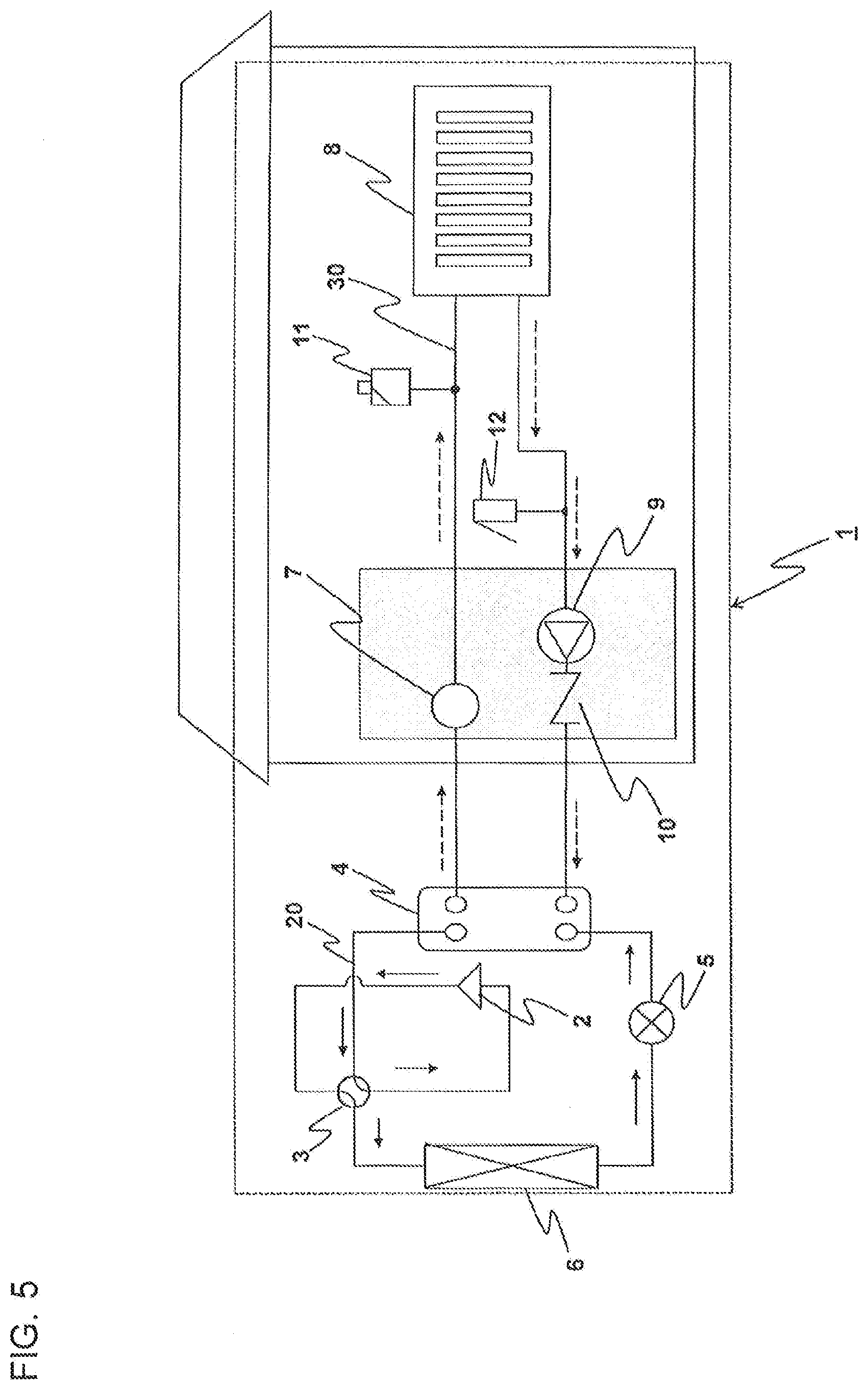
[0013] FIG. 5 is a diagram for illustrating the flows of the refrigerant and the water in the air-conditioning apparatus of Embodiment 1 during a cooling operation.
[0014] FIG. 6 is a diagram for illustrating the flows of the refrigerant and the water when the refrigerant is leaked in the air-conditioning apparatus of Embodiment 1 during the heating operation.
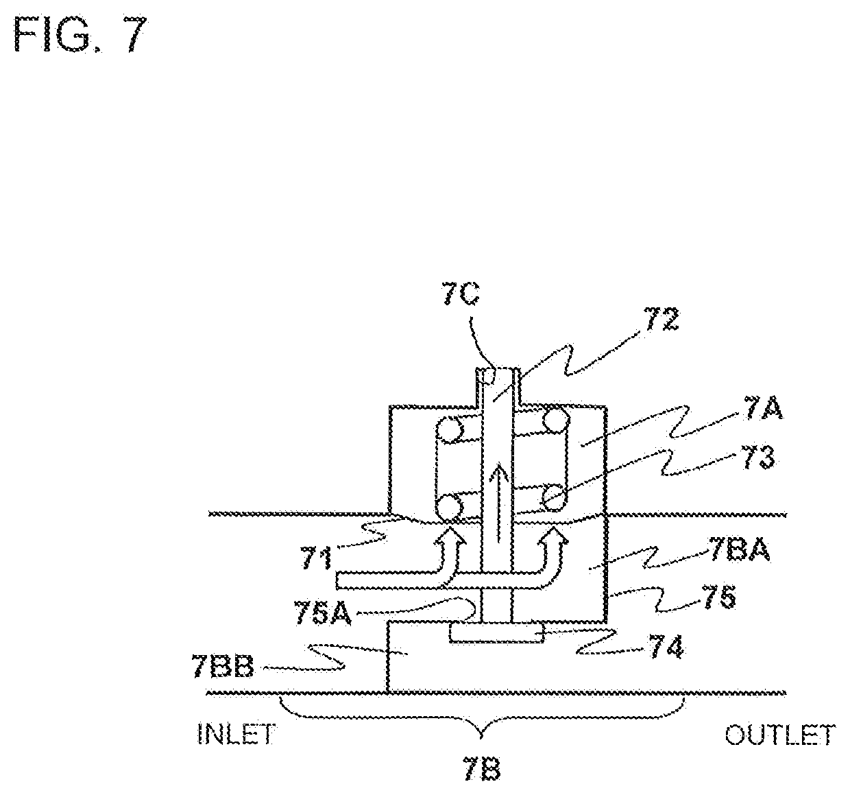
[0015] FIG. 7 is a diagram for illustrating an operation of the pressure regulating valve of Embodiment 1 when the refrigerant is leaked during the heating operation.
[0016] FIG. 8 is a schematic diagram of configuration of an air-conditioning apparatus of Embodiment 2 of the present invention.
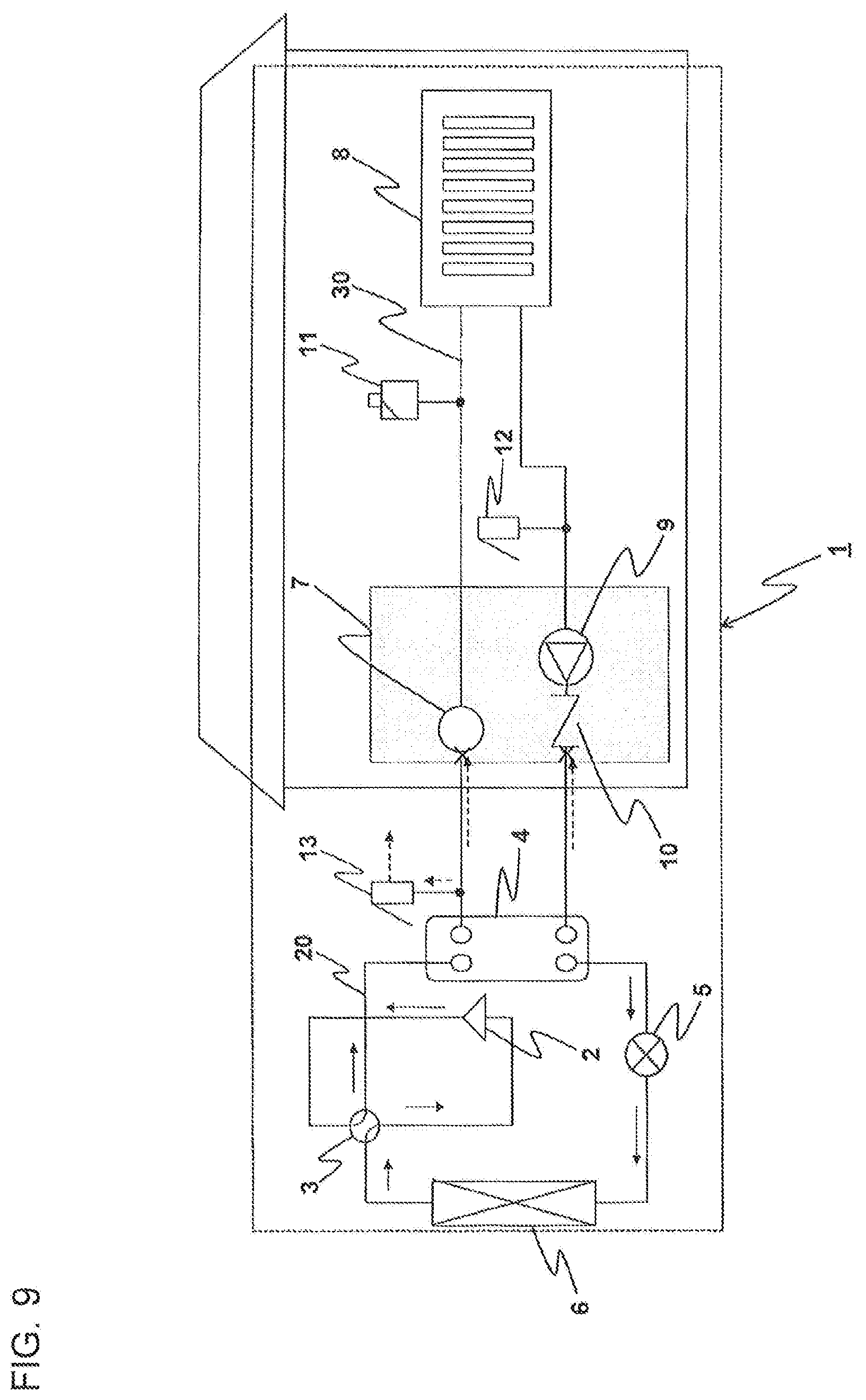
[0017] FIG. 9 is a diagram for illustrating the flows of the refrigerant and the water when the refrigerant is leaked in the air-conditioning apparatus of Embodiment 2 during the heating operation.
DETAILED DESCRIPTION
[0018] Now, heat pump apparatus according to embodiments of the present invention are described in detail by referring to the drawings. Note that, the present invention is not limited to the embodiments described below. Moreover, in the drawings referred to below, sizes of components may be different from the reality in some cases.
Embodiment 1
[0019] FIG. 1 is a schematic diagram of configuration of an air-conditioning apparatus of Embodiment 1 of the present invention. An air-conditioning apparatus 1 includes a refrigerant circuit 20 including a compressor 2, a four-way valve 3, a heat source heat exchanger 6, an expansion valve 5, and an intermediate heat exchanger 4, which are sequentially connected through pipes to form a circuit. Further, the air-conditioning apparatus 1 includes a water circuit 30 including the intermediate heat exchanger 4, a pressure regulating valve 7, a load heat exchanger 8, a pump 9, and a check valve 10, which are sequentially connected through pipes to form a circuit. A flammable refrigerant such as the R32 refrigerant or propane is circulating through the refrigerant circuit 20, and water is circulating through the water circuit 30. In the water circuit 30, an air purge valve 11 is connected to a pipe branching from a pipe connecting the pressure regulating valve 7 and the load heat exchanger 8, and a load safety valve 12 is connected to a pipe branching from a pipe connecting the load heat exchanger 8 and the pump 9.
[0020] The load heat exchanger 8 is installed in an indoor space being a target to be air-conditioned. In the water circuit 30, the pressure regulating valve 7 is connected to a pipe connecting an outlet of the intermediate heat exchanger 4 and an inlet of the load heat exchanger 8. The check valve 10 is a valve configured to allow water to flow from the pump 9 to the intermediate heat exchanger 4 in the water circuit 30, and to inhibit water from flowing from the intermediate heat exchanger 4 to the pump 9 in the water circuit 30.
[0021] The check valve 10 is connected in the water circuit 30 to a pipe connecting an outlet of the load heat exchanger 8 and an inlet of the intermediate heat exchanger 4. The air purge valve 11 is a valve configured to exhaust air generated in or mixed into the water circuit 30 to the outside, and to prevent idle running of the pump 9. In order to exhaust the air efficiently, the air purge valve 11 is connected to a pipe branching from a pipe located at an upper most position in the water circuit 30. The load safety valve 12 is a valve configured to drain the water to suppress pressure increase when pressure in the water circuit 30 is increased. Therefore, the load safety valve 12 is connected to a pipe, which is branched from the vicinity of an inflow side of the pump 9, so as not to be operated by an influence of pressure increase in the pump 9. That is, the air purge valve 11 and the load safety valve 12 are installed in the indoor space. In order to exchange heat between the air and the refrigerant, the heat source heat exchanger 6 is accommodated in an outdoor unit installed in an outdoor space.
(Configuration of Pressure Regulating Valve 7)
[0022] FIG. 2 is a schematic diagram of configuration of the pressure regulating valve of Embodiment 1. Referring to FIG. 2, a configuration of the pressure regulating valve 7 of Embodiment 1 is described. The pressure regulating valve 7 is a valve which is usable only in one direction, and has one inlet and one outlet. The pressure regulating valve 7 has a machine space 7A being a space that water does not flow into, and a water flow part 7B through which water flows. Further, the pressure regulating valve 7 includes a diaphragm 71, a shaft 72, a coil spring 73, a closing plate 74, and an inner wall 75.
[0023] The inner wall 75 is configured to partition an inlet-side water flow part 7BA corresponding to an inflow side of the water flow part 7B, and an outlet-side water flow part 7BB corresponding to an outflow side of the water flow part 7B. An opening portion 75A is formed in the inner wall 75. The diaphragm 71 is arranged in the inlet-side water flow part 7BA, and is configured to partition the machine space 7A and the water flow part 7B. The diaphragm 71 is a member which is deformable in an up-and-down direction in FIG. 2 in accordance with pressure. The shaft 72 is a longitudinal member inserted through the opening portion 75A of the inner wall 75 while being supported by the diaphragm 71. The shaft 72 is arranged so that one distal end thereof is located in the outlet-side water flow part 7BB and an other distal end thereof is located in the machine space 7A. The closing plate 74 is arranged on an end portion of the shaft 72, which is located in the outlet-side water flow part 7BB. An end portion of the shaft 72, which is located in the machine space 7A, is received in a receiving portion 7C formed in the machine space 7A. The closing plate 74 has an area larger than an opening area of the opening portion 75A.
[0024] In the machine space 7A, the coil spring 73 being a spring member is wound around the shaft 72. One end portion of the coil spring 73 is fixed to an inner peripheral surface of the pressure regulating valve 7, which forms the machine space 7A, and an other end portion thereof is fixed to the diaphragm 71. The coil spring 73 urges the diaphragm 71 in a downward direction. The shaft 72 is moved in an upward direction against the force of the coil spring 73. With this, the opening portion 75A of the inner wall 75 is closed by the closing plate 74, and a flow passage connecting the inlet-side water flow part 7BA and the outlet-side water flow part 7BB is interrupted. In Embodiment 1, the shaft 72 and the closing plate 74 correspond to a closing mechanism.
[0025] When the water is circulating through the water circuit 30, the water flows from an inlet of the pressure regulating valve 7 toward an outlet thereof. At this time, a force in the upward direction is applied to the diaphragm 71 due to water pressure. That is, when the water is circulating through the water circuit 30, the force of the coil spring 73 in the downward direction is applied to the diaphragm 71, and the force in the upward direction due to the water pressure is also applied to the diaphragm 71. Therefore, the diaphragm 71 is deformed in an applying direction of a force, which is greater of the force due to the water pressure and the force of the coil spring 73. In Embodiment 1, as the coil spring 73, there is selected a spring having a spring coefficient large enough to push down the shaft 72 in the downward direction against the water pressure to prevent the closing plate 74 from closing the opening portion 75A of the inner wall 75 and interrupting the flow passage of the water during a heating operation, a cooling operation, and a defrosting operation at a normal time during which the refrigerant is not leaked to the water circuit 30. Therefore, as illustrated in FIG. 2, by the force of the coil spring 73, the diaphragm 71 is deformed against the water pressure in the downward direction, that is, in a direction toward the opening portion 75A of the inner wall 75. In association with the deformation of the diaphragm 71, the shaft 72 is moved in the downward direction, and the closing plate 74 is located at a position away from the opening portion 75A.
(Heating Operation)
[0026] Referring to FIG. 3, an operation during the heating operation, which relates to Embodiment 1, is described. FIG. 3 is a diagram for illustrating flows of refrigerant and water in the air-conditioning apparatus of Embodiment 1 during the heating operation. In FIG. 3, solid arrows indicate the flow of the refrigerant, and broken arrows indicate the flow of the water. During the heating operation of the air-conditioning apparatus 1, in the refrigerant circuit 20, refrigerant compressed into a high-temperature, high-pressure state by the compressor 2 passes through the four-way valve 3 and flows into the intermediate heat exchanger 4. The refrigerant flowing into the intermediate heat exchanger 4 is subjected to heat exchange with water circulating through the water circuit 30, and is condensed into liquid refrigerant. At this time, the water circulating through the water circuit 30 is heated. The liquid refrigerant passes through the expansion valve 5 and is expanded into low-temperature and low-pressure two-phase gas-liquid refrigerant. The two-phase gas-liquid refrigerant flows into the heat source heat exchanger 6, and is subjected to heat exchange with outdoor air to be evaporated into gas refrigerant. The gas refrigerant passes through the four-way valve 3, and is sucked into the compressor 2 again to be compressed into a high-temperature, high-pressure state.
[0027] Meanwhile, in the water circuit 30, the high-temperature water heated in the intermediate heat exchanger 4 passes through the pressure regulating valve 7, and flows into the load heat exchanger 8. The high-temperature water flowing into the load heat exchanger 8 is subjected to heat exchange with indoor air to be cooled. At this time, the indoor air is heated. The cooled water sequentially passes through the pump 9 and the check valve 10 and flows into the intermediate heat exchanger 4 again.
[0028] An operation of the pressure regulating valve 7 during the heating operation is described. FIG. 4 is a diagram for illustrating the operation of the pressure regulating valve of Embodiment 1 during the heating operation. As described above, the coil spring 73 of the pressure regulating valve 7 has a spring coefficient large enough to push down the shaft 72 in the downward direction against the water pressure to prevent the closing plate 74 from interrupting the flow passage of the water due to the pressure of the water passing through the pressure regulating valve 7. Therefore, during the heating operation, the coil spring 73 of the pressure regulating valve 7 pushes down the diaphragm 71, and pushes down the shaft 72 and the closing plate 74. As a result, in the pressure regulating valve 7, the flow passage is formed between the inlet-side water flow part 7BA and the outlet-side water flow part 7BB, and the high-temperature water flowing into the pressure regulating valve 7 through the inlet flows out therefrom through the outlet.
(Cooling Operation)
[0029] Referring to FIG. 5, an operation during the cooling operation, which relates to Embodiment 1, is described. FIG. 5 is a diagram for illustrating the flows of the refrigerant and the water in the air-conditioning apparatus of Embodiment 1 during the cooling operation. In FIG. 5, solid arrows indicate the flow of the refrigerant, and broken arrows indicate the flow of the water. During the cooling operation, in the refrigerant circuit 20, refrigerant compressed into a high-temperature, high-pressure state by the compressor 2 passes through the four-way valve 3 and flows into the heat source heat exchanger 6. The refrigerant flowing into the heat source heat exchanger 6 is subjected to heat exchange with air to be turned into liquid refrigerant. The liquid refrigerant passes through the expansion valve 5 and is expanded into low-temperature and low-pressure two-phase gas-liquid refrigerant. The two-phase gas-liquid refrigerant flows into the intermediate heat exchanger 4, and is subjected to heat exchange with water to be evaporated into gas refrigerant. At this time, the water circulating through the water circuit 30 is cooled. The gas refrigerant passes through the four-way valve 3, and is sucked into the compressor 2 again to be compressed into a high-temperature, high-pressure state.
[0030] Meanwhile, in the water circuit 30, the low-temperature water cooled in the intermediate heat exchanger 4 passes through the pressure regulating valve 7, and flows into the load heat exchanger 8. The low-temperature water flowing into the load heat exchanger 8 is subjected to heat exchange with the indoor air to be heated. At this time, the indoor air is cooled. The heated water sequentially passes through the pump 9 and the check valve 10 and flows into the intermediate heat exchanger 4 again.
[0031] An operation of the pressure regulating valve 7 during the cooling operation is described. Similarly to the case during the heating operation, as illustrated in FIG. 4, in the pressure regulating valve 7, the flow passage is formed between the machine space 7A and the water flow part 7B, and the low-temperature water flowing into the pressure regulating valve 7 through the inlet flows out therefrom through the outlet.
(Defrosting Operation)
[0032] An operation of the air-conditioning apparatus 1 of Embodiment 1 during the defrosting operation is described. The defrosting operation is executed when frost is formed on the heat source heat exchanger 6 by the heating operation. The operation during the defrosting operation is similar to the operation during the cooling operation. That is, as illustrated in FIG. 5, in the refrigerant circuit 20, the refrigerant compressed into a high-temperature, high-pressure state by the compressor 2 passes through the four-way valve 3, and flows into the heat source heat exchanger 6. The frost formed on the heat source heat exchanger 6 is melted and removed by the high-temperature and high-pressure refrigerant flowing into the heat source heat exchanger 6. The other operation is similar to the operation during the cooling operation.
(When Refrigerant is Leaked)
[0033] As described above, during the cooling operation and the defrosting operation, the low-temperature refrigerant flows into the intermediate heat exchanger 4, and cools the water flowing through the intermediate heat exchanger 4. Therefore, depending on circumstances, the water flowing through the intermediate heat exchanger 4 may be frozen, and there is a risk in that the intermediate heat exchanger 4 may be broken due to cubical expansion of the water caused by the freezing. Further, there is a risk in that fatigue fracture caused by the pressure increase may occur in the intermediate heat exchanger 4 due to the breakage caused by abnormal increase of pressure of the refrigerant or as a result of repetitive operations. Further, thinning of the intermediate heat exchanger 4 caused by corrosion of components of the intermediate heat exchanger 4 may lead to decrease in strength of the intermediate heat exchanger 4, and there is also a risk in that the breakage of the intermediate heat exchanger 4 may be promoted.
[0034] When the intermediate heat exchanger 4 is broken, due to a difference in pressure between the refrigerant flowing through the refrigerant circuit 20 and the water flowing through the water circuit 30, the refrigerant is mixed into the water circuit 30. When the refrigerant is mixed into the water circuit 30, the refrigerant is gasified due to an effect of pressure reduction, thereby causing increase of the pressure in the water circuit 30. When the pressure in the water circuit 30 is increased, the water is drained through the load safety valve 12 mounted in the water circuit 30. At this time, through the drainage of water, the refrigerant mixed into the water inside the water circuit 30 is exhausted to the indoor space. As a result, a flammable region is formed, and when the flammable region reaches an ignition source, there is a risk of causing ignition. Similarly, the gasified refrigerant mixed into the water circuit 30 is exhausted through the air purge valve 11 and forms the flammable region, with the result that there is a risk of causing ignition. However, in Embodiment 1, the pressure regulating valve 7 is provided. Thus, the refrigerant is prevented from being exhausted to the indoor space and forming the flammable region.
[0035] Now, an operation of the pressure regulating valve 7 of Embodiment 1 when the refrigerant is leaked is described. FIG. 6 is a diagram for illustrating the flows of the refrigerant and the water when the refrigerant is leaked in the air-conditioning apparatus of Embodiment 1 during the heating operation. FIG. 7 is a diagram for illustrating an operation of the pressure regulating valve of Embodiment 1 when the refrigerant is leaked during the heating operation. When the refrigerant is leaked, the refrigerant leaks to the water circulating through the water circuit 30. With this, the water pressure of the water flowing into the pressure regulating valve 7 through the inlet thereof is increased to be greater than the force of the coil spring 73 of the pressure regulating valve 7. As a result, the diaphragm 71 is deformed upward, that is, in a direction to be away from the opening portion 75A of the inner wall 75 against the force of the coil spring 73. The shaft 72 is moved in association with the deformation of the diaphragm 71. With this, as illustrated in FIG. 7, the closing plate 74 is located at a position at which the closing plate 74 closes the opening portion 75A. When the opening portion 75A of the inner wall 75 is closed by the closing plate 74, in the pressure regulating valve 7, the flow passage from the inlet-side water flow part 7BA to the outlet-side water flow part 7BB is interrupted, thereby preventing the water, which flows into the pressure regulating valve 7 through the inlet thereof, from flowing out of the pressure regulating valve 7 through the outlet thereof. Further, the flow passage is interrupted so that the water pressure applied to the inlet of the pressure regulating valve 7 is further increased, thereby also increasing the pressure of pressing the closing plate 74 against a peripheral edge of the opening portion 75A of the inner wall 75 by the diaphragm 71 and the shaft 72. As a result, an amount of the refrigerant leaking to the water circulating through the water circuit 30 is reduced.
[0036] As described above, in Embodiment 1, the pressure regulating valve 7 is configured to be operated when the water pressure is increased due to the leakage of the refrigerant to the water circulating through the water circuit 30. Therefore, even under a state in which electric power is not supplied to the air-conditioning apparatus 1, when a situation of leakage of the refrigerant occurs, the flow passage in the water circuit 30 is interrupted by the pressure regulating valve 7, thereby preventing the leakage of the refrigerant to the indoor space.
[0037] Further, in the air-conditioning apparatus described in Patent Literature 1, a time period is required from detection by a leakage detection device to interruption by a first valve and a second valve. Therefore, there is a risk in that the refrigerant thus leaked may flow further beyond the first valve and the second valve. As a result, there is a risk in that the refrigerant may be leaked to the indoor space in which a load heat exchanger of a fluid circuit is arranged. On the other hand, according to Embodiment 1, the pressure regulating valve 7 is operated in response to the increase in water pressure caused by the leakage of the refrigerant. Thus, the flow passage can be interrupted in a short period of time. Therefore, the amount of the refrigerant leaking to the water circuit 30 can be reduced.
[0038] The pressure regulating valve 7 is interposed at the pipe connecting the outlet of the intermediate heat exchanger 4 and the inlet of the load heat exchanger 8 at a portion between the outlet of the intermediate heat exchanger 4 and the air purge valve 11. Therefore, the refrigerant leaking to the water inside the water circuit 30 is prevented from reaching the air purge valve 11. As a result, the leakage of the refrigerant to the indoor space is prevented.
[0039] Further, through interruption of the flow passage of the water in the pressure regulating valve 7, the flow of the water in the water circuit 30 is stopped, and the check valve 10 is set to a closed state. As a result, the refrigerant leaked from the intermediate heat exchanger 4 and flowing into the water circuit 30 is prevented from flowing from the pressure regulating valve 7 and the check valve 10 to a side on which the load heat exchanger 8 is located, thereby preventing the refrigerant from reaching the air purge valve 11 and preventing the refrigerant from reaching the load safety valve 12. Therefore, the leakage of the refrigerant to the indoor space can be prevented. Further, the pressure increase of the water flowing through the load heat exchanger 8, pipes extending throughout the indoor space, and welding portions of the pipes can be prevented. Therefore, the water including the refrigerant can be prevented from leaking exceeding the pressure resistance of the load heat exchanger 8, the pipes in the indoor space, and the welding portions of the pipes.
Embodiment 2
[0040] FIG. 8 is a schematic diagram of configuration of an air-conditioning apparatus of Embodiment 2 of the present invention. Embodiment 2 is different from Embodiment 1 in that an outdoor-space safety valve 13 is connected to a pipe branching from a pipe connecting the intermediate heat exchanger 4 and the pressure regulating valve 7. Operating pressure, that is, valve opening pressure of the outdoor-space safety valve 13 is equal to or higher than operating pressure of the closing plate 74 of the pressure regulating valve 7, that is, fluid interruption pressure of the pressure regulating valve 7. In other words, the fluid interruption pressure of the pressure regulating valve 7 is equal to or lower than the operating pressure of the outdoor-space safety valve 13. It is desired that the valve opening pressure of the outdoor-space safety valve 13 be higher than the operating pressure of the closing plate 74. Further, it is desired that the outdoor-space safety valve 13 and a drain outlet extending from the outdoor-space safety valve 13 be installed in an open space such as an open-air space or a room having a large floor area.
[0041] In Embodiment 2, a heating operation, a cooling operation, and a defrosting operation are executed in a manner similar to those in Embodiment 1 described above, and hence description thereof is omitted. An operation of the air-conditioning apparatus 1 of Embodiment 2 when the refrigerant is leaked from the intermediate heat exchanger 4 to the water circuit 30 is described. FIG. 9 is a diagram for illustrating the flows of the refrigerant and the water when the refrigerant is leaked in the air-conditioning apparatus of Embodiment 2 during the heating operation. In FIG. 9, solid arrows indicate the flow of the refrigerant, and broken arrows indicate the flow of the water. When the refrigerant is leaked from the intermediate heat exchanger 4 to the water circuit 30, and the pressure of the water circulating through the water circuit 30 is increased, the pressure regulating valve 7 is operated to interrupt the flow passage of the water. Such an operation is similar to the operation in Embodiment 1 described above. In Embodiment 2, after the leakage of the refrigerant, when the pressure increase of the water inside the water circuit 30 is continued so that the pressure of the water inside the water circuit 30 exceeds the operating pressure of the outdoor-space safety valve 13, the outdoor-space safety valve 13 releases the water and the refrigerant to the open space. Then, the pressure in the water circuit 30 is gradually reduced. Through the reduction of the pressure in the water circuit 30, the outdoor-space safety valve 13 is closed, and the release of the water and the refrigerant to the open space is stopped.
[0042] According to Embodiment 2, the outdoor-space safety valve 13 is provided on the pipe branching from the pipe connecting the intermediate heat exchanger 4 and the pressure regulating valve 7. Therefore, it is possible to prevent the refrigerant flowing into the water circuit 30 through the broken part of the intermediate heat exchanger 4 from reaching the indoor space, and to prevent the increase of the pressure applied to the pipe connecting the check valve 10 and the intermediate heat exchanger 4 and the pipe connecting the intermediate heat exchanger 4 and the pressure regulating valve 7. Further, when the refrigerant is leaked, the increase of the pressure applied to those pipes is prevented. Thus, components having low resistance to back pressure can be used for the pressure regulating valve 7, the check valve 10, and the pipe connecting each of the pressure regulating valve 7 and the check valve 10 to the intermediate heat exchanger 4. That is, components having special specification do not need to be prepared for the pressure regulating valve 7, the check valve 10, and the pipe connecting each of the pressure regulating valve 7 and the check valve 10 to the heat exchanger 4. Thus, this configuration is economical.
* * * * *
D00000
D00001
D00002
D00003
D00004
D00005
D00006
D00007
D00008
D00009
XML
uspto.report is an independent third-party trademark research tool that is not affiliated, endorsed, or sponsored by the United States Patent and Trademark Office (USPTO) or any other governmental organization. The information provided by uspto.report is based on publicly available data at the time of writing and is intended for informational purposes only.
While we strive to provide accurate and up-to-date information, we do not guarantee the accuracy, completeness, reliability, or suitability of the information displayed on this site. The use of this site is at your own risk. Any reliance you place on such information is therefore strictly at your own risk.
All official trademark data, including owner information, should be verified by visiting the official USPTO website at www.uspto.gov. This site is not intended to replace professional legal advice and should not be used as a substitute for consulting with a legal professional who is knowledgeable about trademark law.