Electric Coolant Pump
Bauer; Swen-Juri ; et al.
U.S. patent application number 16/349602 was filed with the patent office on 2019-11-14 for electric coolant pump. The applicant listed for this patent is Mahle International GmbH. Invention is credited to Swen-Juri Bauer, Michael Baumann, Andreas Gruener, Andrea Teubner.
| Application Number | 20190345868 16/349602 |
| Document ID | / |
| Family ID | 62026387 |
| Filed Date | 2019-11-14 |


| United States Patent Application | 20190345868 |
| Kind Code | A1 |
| Bauer; Swen-Juri ; et al. | November 14, 2019 |
ELECTRIC COOLANT PUMP
Abstract
An electric coolant pump may include at least one first coolant inlet, at least one second coolant inlet, a coolant outlet, and a valve device. The valve device may be configured to, based on a selected operating point and a pressure in a coolant, at least one of open and close at least one of the at least one first coolant inlet and the at least one second coolant inlet. The valve device may be integrated in a body of the coolant pump.
| Inventors: | Bauer; Swen-Juri; (Stuttgart, DE) ; Baumann; Michael; (Ammerbuch, DE) ; Gruener; Andreas; (Hattenhofen, DE) ; Teubner; Andrea; (Rainau-Schwabsberg, DE) | ||||||||||
| Applicant: |
|
||||||||||
|---|---|---|---|---|---|---|---|---|---|---|---|
| Family ID: | 62026387 | ||||||||||
| Appl. No.: | 16/349602 | ||||||||||
| Filed: | October 25, 2017 | ||||||||||
| PCT Filed: | October 25, 2017 | ||||||||||
| PCT NO: | PCT/EP2017/077268 | ||||||||||
| 371 Date: | May 13, 2019 |
| Current U.S. Class: | 1/1 |
| Current CPC Class: | F01P 7/164 20130101; F04D 15/00 20130101; F01P 2007/146 20130101; F04D 15/0022 20130101; F01P 2025/50 20130101; F01P 7/162 20130101; F01P 5/10 20130101; F01P 7/14 20130101; F04D 15/0016 20130101; F01P 5/12 20130101; F01P 7/16 20130101; F01P 11/16 20130101; F01P 7/161 20130101; F01P 2005/125 20130101; F16K 31/1221 20130101 |
| International Class: | F01P 5/12 20060101 F01P005/12; F01P 7/14 20060101 F01P007/14; F01P 7/16 20060101 F01P007/16 |
Foreign Application Data
| Date | Code | Application Number |
|---|---|---|
| Nov 14, 2016 | DE | 102016222307.0 |
| Jan 19, 2017 | DE | 102017200874.1 |
Claims
1. An electric coolant pump comprising: at least one first coolant inlet, at least one second coolant inlet, and a coolant outlet; and a valve device configured to, based on a selected operating point and a pressure in a coolant, at least one of open and close at least one of the at least one first coolant inlet and the at least one second coolant inlet; wherein the valve device is integrated in a body of the coolant pump.
2. The coolant pump as claimed in claim 1, wherein, in a first operating point, the coolant pump is switched off and the at least one first coolant inlet is open.
3. The coolant pump as claimed in claim 2, wherein: in a second operating point, the coolant pump has a rotational speed at which the at least one first coolant inlet is open and the at least one second coolant inlet is closed; in a third operating point, the coolant pump has a second rotational speed at which the at least one first coolant inlet and the at least one second coolant inlet are open; and in a fourth operating point, the coolant pump has a third rotational speed at which the at least one first coolant inlet is closed and the at least one second coolant inlet is open.
4. The coolant pump as claimed in claim 3, wherein the valve device includes a valve body, and wherein at least one of: in the first operating point and the second operating point, the valve body is arranged in a first position, in which the valve body blocks the at least one second coolant inlet and uncovers the at least one first coolant inlet; in the third operating point, the valve body is arranged in a second position, in which the valve body uncovers the at least one first coolant inlet and the at least one second coolant inlet; and in the fourth operating point, the valve body is arranged in a third position, in which the valve body blocks the at least one first coolant inlet and uncovers the at least one second coolant inlet.
5. The coolant pump as claimed in claim 1, wherein the valve device is continuously adjustable based on a rotational speed of the coolant pump.
6. The coolant pump as claimed in claim 4, wherein the valve body is structured as a valve piston and is adjustable in a translatory manner.
7. The coolant pump as claimed in claim 4, further comprising a spring device prestressing the valve body in the first position.
8. The coolant pump as claimed in claim 1, further comprising a temperature sensor and a control device communicatively connected thereto configured to control a power of the coolant pump based on a temperature of the coolant.
9. A motor vehicle comprising an internal combustion engine, a radiator, a heat exchanger, and a coolant pump, the coolant pump including: at least one first coolant inlet, at least one second coolant inlet, and a coolant outlet; and a valve device configured to at least one of open and close at least one of the at least one first coolant inlet and the at least one second coolant inlet based on a selected operating point of the coolant pump and a pressure in a coolant, the valve device integrated in a body of the coolant pump; wherein the at least one first coolant inlet and the coolant outlet are connected to the internal combustion engine, and the at least one second coolant inlet is connected to the radiator.
10. The motor vehicle as claimed in claim 9, further comprising an electric motor and an electrical energy accumulator, wherein the coolant pump further includes at least one third coolant inlet connected to at least one of the electric motor and the electrical energy accumulator.
11. The motor vehicle as claimed in claim 10, wherein the at least one third coolant inlet and the coolant outlet are connected to at least one of the electric motor and the electrical energy accumulator, and the at least one second coolant inlet is connected to the radiator.
12. The motor vehicle as claimed in claim 9, further comprising a temperature-regulated valve which is configured to, at a limit temperature, open a bypass between the coolant outlet and the at least one second coolant inlet.
13. The motor vehicle as claimed in claim 9, wherein: in a first operating point of the coolant pump, the coolant pump is switched off and the at least one first coolant inlet is open; in a second operating point of the coolant pump, the coolant pump has a rotational speed at which the at least one first coolant inlet is open and the at least one second coolant inlet is closed; in a third operating point of the coolant pump, the coolant pump has a second rotational speed at which the at least one first coolant inlet and the at least one second coolant inlet are open; and in a fourth operating point of the coolant pump, the coolant pump has a third rotational speed at which the at least one first coolant inlet is closed and the at least one second coolant inlet is open.
14. The motor vehicle as claimed in claim 13, wherein the valve device includes a valve body, and wherein at least one of: in the first operating point and the second operating point, the valve body is arranged in a first position, in which the valve body blocks the at least one second coolant inlet and uncovers the at least one first coolant inlet; in the third operating point, the valve body is arranged in a second position, in which the valve body uncovers the at least one first coolant inlet and the at least one second coolant inlet; and in the fourth operating point, the valve body is arranged in a third position, in which the valve body blocks the at least one first coolant inlet and uncovers the at least one second coolant inlet.
15. The motor vehicle as claimed in claim 9, wherein the valve device is continuously adjustable based on a rotational speed of the coolant pump.
16. The motor vehicle as claimed in claim 14, wherein the valve body is structured as a valve piston and is adjustable in a translatory manner.
17. The motor vehicle as claimed in claim 14, further comprising a spring device prestressing the valve body in the first position.
18. The motor vehicle as claimed in claim 9, further comprising a temperature sensor and a control device communicatively connected thereto configured to control a power of the coolant pump based on a temperature of the coolant.
19. An electric coolant pump comprising: a plurality of first coolant inlets, a plurality of second coolant inlets, and a coolant outlet; and a valve device configured to, based on a selected operating point and a pressure in a coolant, at least one of open and close at least one of i) at least one of the plurality of first coolant inlets and ii) at least one of the plurality of second coolant inlets; wherein the valve device is integrated in a body of the coolant pump.
20. The coolant pump as claimed in claim 19, wherein: in a first operating point, the coolant pump is switched off and at least one of the plurality of first coolant inlets is open; in a second operating point, the coolant pump has a rotational speed at which at least one of the plurality of first coolant inlets is open and at least one of the plurality of second coolant inlets is closed; in a third operating point, the coolant pump has a second rotational speed at which at least one of the plurality of first coolant inlets and at least one of the plurality of second coolant inlets are open; and in a fourth operating point, the coolant pump has a third rotational speed at which at least one of the plurality of first coolant inlets is closed and at least one of the plurality of second coolant inlets is open.
Description
CROSS-REFERENCE TO RELATED APPLICATIONS
[0001] This application claims priority to International Patent Application No. PCT/EP2017/077268 filed on Oct. 25, 2017, to German Patent Application No. DE 10 2017 200 874.1 filed on Jan. 19, 2017, and to German Patent Application No. DE 10 2016 222 307.0 filed on Nov. 14, 2016, the contents of each of which are hereby incorporated by reference in their entirety.
TECHNICAL FIELD
[0002] The present invention relates to an electric coolant pump for delivering a coolant. The invention moreover relates to a motor vehicle having an internal combustion engine and such a coolant pump.
BACKGROUND
[0003] In modern motor vehicles, a coolant pump is usually used for cooling an internal combustion engine, wherein the cooling power is usually controlled via a thermostat valve. Such a thermostat valve can open a bypass circumventing a radiator, for example when only a low cooling power is required. Such a thermostat valve often possesses an expansion element which enables comparatively simple temperature-dependent control.
[0004] However, the coolant pumps known from the prior art are disadvantageous in that they often run at constantly high power and are controlled exclusively via a thermostat valve. A comparatively high amount of energy is thus needed to operate the coolant pump. A further and decisive disadvantage is that the known coolant pumps and the thermostat valves arranged separately therefrom need a comparatively large installation space.
[0005] The present invention is therefore concerned with the problem of providing an improved or at least an alternative embodiment for an electric coolant pump, which, in particular, overcomes the disadvantages known from the prior art.
SUMMARY
[0006] According to the invention, this problem is solved by the subject mater of the independent claim(s). Advantageous embodiments are the subject matter of the dependent claims).
[0007] The present invention is based on the general idea of integrating a valve device in a coolant pump and, at the same time, no longer operating this expensively under a constantly high load and therefore with a comparatively high amount of energy, but instead providing a plurality of power stages in the manner of operating points, wherein the valve device controls a coolant flow depending on the selected operating point of the coolant pump and the pressure generated by this in the process. The electric coolant pump according to the invention serves in a known manner for delivering a coolant, for example in the cooling circuit of an internal combustion engine, and is adjustable between a plurality of operating points. The electric coolant pump has at least one first coolant inlet, at least one second coolant inlet and a coolant outlet, as well as a valve device which is formed such that, depending on the selected operating point of the coolant pump and therefore the pressure p in the coolant, it opens or closes at least one first or second coolant inlet or simultaneously opens at least one first and second coolant inlet, wherein the valve device is integrated in the coolant pump and thus optimally arranged in terms of the installation space. In this case, it is particularly advantageous that the coolant pump and the valve device form a common unit or the valve device is integrated in the coolant pump. In particular, a particularly compact design can thus be achieved, which is highly advantageous in modern engine compartments and the limited spatial conditions associated therewith. Moreover, such a coolant pump can also be prefabricated externally and inserted into the motor vehicle as a fully pre-assembled unit, thereby resulting in assembly advantages.
[0008] In a further advantageous embodiment of the solution according to the invention, in the first operating point, the coolant pump is switched off and at least one first coolant inlet is opened. In this case, the first operating point of the coolant pump is therefore synonymous with an off state. In this case, the first operating point is used in particular during a cold-start phase of the internal combustion engine, in which additional cooling of the internal combustion engine is not desired. A second operating point provides a greater delivery power and thus represents a comfort mode in which only an average cooling power of the internal combustion engine is required, which can also be achieved, for example, via a heat exchanger of an air-conditioning system of a motor vehicle. The third operating point of the cooling pump is represented by a cooling mode, for example, in which the valve device is set such that the coolant flow circulates via a radiator, the heat exchanger and the internal combustion engine. By selecting the operating points, the amount of energy to be used for this is considerably lower than in a coolant pump running constantly under full load, in which, during a cold-start phase, for example, the coolant flow is simply conducted past the radiator by a valve formed as a bypass valve.
[0009] The valve device expediently has a valve body which, in the first and second operating point, assumes a first position, in which it blocks at least one second coolant inlet and uncovers at least one first coolant inlet. In this case, the second coolant inlet is connected to a radiator of the motor vehicle, whilst the first coolant inlet is connected, for example, to the heat exchanger of an air-conditioning system of the motor vehicle. In the second operating point, and therefore in the first position of the valve body, in which only an average cooling power is required, the coolant flow is therefore not conducted via a radiator of the motor vehicle. Additionally or alternatively, it can be provided that the valve device has a valve body which, in the third operating point, assumes a second position, in which it uncovers at least one first coolant inlet and at least one second coolant inlet. In the third operating point of the coolant pump, and therefore in the second position of the valve body, this therefore brings about a coolant flow which circulates via a vehicle radiator, a heat exchanger and the internal combustion engine. In this case, the valve body assumes the second position solely as a result of the increased coolant pressure in the third operating point. In the fourth operating point, the valve body assumes a third position, in which it blocks at least one first coolant inlet and uncovers a second coolant inlet.
[0010] In a further advantageous embodiment of the solution according to the invention, a spring device is provided, which prestresses the valve body in its first position. To adjust the valve body between its first and second position, the coolant pressure must therefore increase, which is usually only achieved if the coolant pump is adjusted from its second operating point to its third operating point. In this case, the coolant pressure p.sub.2, p.sub.3 counteracts the pressure P.sub.F applied by the spring device.
[0011] A temperature sensor and a control device communicatively connected thereto are expediently provided for controlling the operating points and therefore the power of the coolant pump depending on the temperature of the coolant. To enable the respective operating point of the coolant pump to be selected, it is necessary to determine a cooling requirement, which is possible via the temperature sensor provided according to the invention and the control device communicatively connected thereto according to the invention. Below a particular coolant temperature, for example during a cold-start phase of the internal combustion engine, cooling of the coolant and therefore cooling of the internal combustion engine are not desired, so that, in this case, the control device adjusts the coolant pump to its first operating point, i.e. switches it off or allows it to be switched off, for example. If the temperature of the coolant increases, the control device can detect this via the temperature sensor and, according to a characteristic map, for example, adjusts the coolant pump to its second operating point, in which an average cooling power is achieved. If the load on the internal combustion engine increases significantly, for example when driving uphill, the temperature of the coolant also increases, whereupon the control device adjusts the coolant pump to its third operating point, in which the coolant flow is conducted via the heat exchanger and the radiator and not, as in the second operating point, exclusively via a heat exchanger of an air-conditioning system of the motor vehicle, for example, and thus generates a considerably higher cooling power for cooling the internal combustion engine. If the load on the internal combustion engine increases further, then the temperature of the coolant also increases, whereupon the control device adjusts the coolant pump to its fourth operating point, in which the coolant flow is conducted exclusively via the radiator and not, as in the third operating point, additionally via the heat exchanger of the air-conditioning system of the motor vehicle. Therefore, a temperature-dependent control of the operating points of the coolant pump is also possible via the temperature sensor and the control device communicatively connected thereto.
[0012] The present invention is further based on the general idea of equipping a motor vehicle with an internal combustion engine, a radiator, a heat exchanger, an air-conditioning system and a coolant pump described above, wherein at least one first coolant inlet and the coolant outlet are connected to the internal combustion engine, whilst at least one second coolant inlet is connected to the radiator. Such a motor vehicle according to the invention requires considerably less electrical energy to operate the coolant pump than is the case in the hitherto constantly running coolant pumps. However, not only can electrical energy be saved thereby, but also fuel.
[0013] Further important features and advantages of the invention are revealed in the subclaims, in the drawings and in the associated description of the figures with reference to the drawings.
[0014] Or course, the features mentioned above and those still to be explained below can be applied not only in the combination described in each case but also in other combinations or in isolation, without deviating from the scope of the present invention.
[0015] Preferred exemplary embodiments of the invention are illustrated in the drawings and will be explained in more detail in the description below, wherein identical reference signs relate to identical or similar or functionally identical components.
BRIEF DESCRIPTION OF THE DRAWINGS
[0016] The drawings show, in each case schematically:
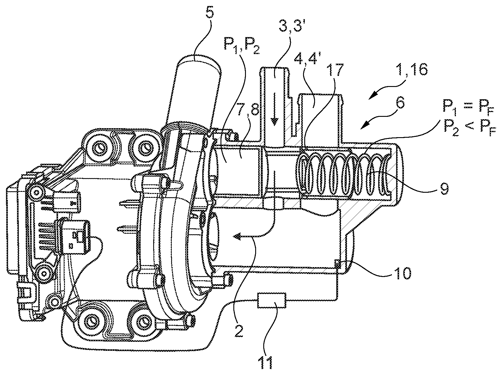
[0017] FIG. 1--shows a partly sectional coolant pump according to the invention, having a valve device with a valve body located in the first position,
[0018] FIG. 2--shows an illustration as in FIG. 1, but with the valve body located in its third position,
[0019] FIG. 3--shows an exploded illustration of the coolant pump according to the invention with a valve device,
[0020] FIG. 4--shows a schematic diagram of an installation situation of the coolant pump according to the invention in a motor vehicle according to the invention,
[0021] FIG. 5--shows an illustration as in FIG. 4, but with a third coolant inlet in the coolant pump.
DETAILED DESCRIPTION
[0022] According to FIGS. 1 to 5, an electric coolant pump 1 according to the invention for delivering a coolant 2 has at least one first coolant inlet 3, 3', at least one second coolant inlet 4, 4' and a coolant outlet 5. In this case, the coolant pump 1 according to the invention is adjustable between a plurality of operating points, in particular between a first, a second, a third and a fourth operating point. In addition, the coolant pump 1 according to the invention has a valve device 6, which is integrated in the coolant pump 1 and which is formed such that, depending on the selected operating point of the coolant pump 1 and therefore the coolant pressure p, opens or closes the at least one first or second coolant inlet 3, 3', 4, 4' or simultaneously opens at least one first and second coolant inlet 3, 3', 4, 4'.
[0023] As can be seen in FIGS. 1, 2, and 4, the coolant pump 1 according to the invention and the valve device 6 form a common unit 16 which, compared to hitherto used coolant pumps with thermostat valves arranged separately therefrom, is considerably compacter in design and thus offers considerable advantages in terms of installation space.
[0024] In this case, a first operating point of the coolant pump 1 according to the invention has, for example, a delivery power of 0 l/min and a pressure p.sub.1 of 0 bar. In this state, i.e. in the first operating point, delivery of coolant 2 through the coolant pump 1 does not take place, so that this is switched off, for example. A second operating point of the coolant pump 1 has, for example, a delivery power of ca. 125 l/min and a pressure p.sub.2 of ca. 0.4 bar, whereas a third operating point has, for example, a delivery power of ca. 220 l/min and a pressure p.sub.3 of ca. 1.4 bar.
[0025] The pressures in the respective operating points are achieved by a corresponding rotational speed of the coolant pump 1, so that, in the second operating point, the coolant pump 1 has a rotational speed in which at least one first coolant inlet 3, 3' is opened and at least one second coolant inlet 4, 4' is closed, wherein, in the third operating point, the coolant pump 1 has a rotational speed in which at least one first coolant inlet 3, 3' and at least one second coolant inlet 4, 4' are opened, and wherein, in a fourth operating point, the coolant pump 1 has a rotational speed in which at least one first coolant inlet 3, 3' is closed and at least one second coolant inlet 4, 4' is opened.
[0026] With regard to the construction of the valve device 6 according to the invention, reference is made below to FIGS. 1 to 3, from which it can be seen that the valve device 6 possesses a valve body 7 which, in this case, is formed as an adjustable valve piston 8 and which, in the first and second operating point, assumes a first position (c.f. FIGS. 1 and 4), in which it blocks at least one second coolant inlet 4, 4' and uncovers at least one first coolant inlet 3, 3'. In the third operating point, on the other hand, the valve body 7 assumes a second position, in which it uncovers at least one first coolant inlet 3, 3' and at least one second coolant inlet 4, 4'. In the fourth operating point, the valve body 7 assumes a third position, in which it blocks at least one first coolant inlet 3, 3' and uncovers a second coolant inlet 4, 4' (c.f. FIG. 2). Moreover, a spring device 9, for example a simple helical spring, is provided, which prestresses the valve body 7 in its first position, in which at least one second coolant inlet 4, 4' is blocked. In this case, the spring device 9 exerts a force on the valve body 7 which, in relation to the surface thereof, corresponds to a pressure p.sub.F. A temperature sensor 10 and a control device 11 communicatively connected thereto can likewise be provided for controlling the operating points of the coolant pump 1 depending on the temperature of the coolant 2. In this case, the valve device 6 is continuously adjustable depending on the rotational speed of the coolant pump 1. In this case, it is, of course, also alternatively conceivable that, instead of the valve body 7 formed as a valve piston 8, the valve device 6 according to the invention can also have other valve bodies 7, so that the valve device 6 can also be formed as a ball valve or as a disk valve, for example.
[0027] The valve piston 8 illustrated according to FIG. 3 possesses leakage openings 17 for pressure equalization.
[0028] Observation of FIG. 4 now shows a motor vehicle 12 having an internal combustion engine 13, a radiator 14, a heat exchanger 15 in an air-conditioning system which is not otherwise illustrated, and having a coolant pump 1 according to the passages above. In this case, a first coolant inlet 3, 3' of the coolant pump 1, like the coolant outlet 5, is connected to the internal combustion engine 13, whilst a second coolant inlet 4, 4' is connected to the radiator 14.
[0029] In this case, in terms of controlling a coolant flow 2, the coolant pump 1 according to the invention functions as follows:
[0030] Cooling of the internal combustion engine 13 is not required or desired upon a cold start thereof in order to accelerate the heating of the internal combustion engine 13 and therefore achieve a more rapid lowering of emissions. During this cold-start phase, the coolant pump 1 is located in its first operating point, in which it does not bring about a build-up of pressure and does not deliver coolant 2 and is therefore switched off. If the temperature of the coolant 2 increases, this is detected via the temperature sensor 10, for example, which, in the present case according to FIG. 1, is arranged in the region of the coolant pump 1, but can, of course, additionally or alternatively also be positioned at another point in the coolant system. If the temperature of the coolant 2 reaches a certain value, the control device 11 connected to the temperature sensor 10 adjusts the coolant pump 1 to its second operating point, in which at least one second coolant inlet 4, 4' is still closed and a coolant flow circulates exclusively via the internal combustion engine 13 and, for example, the heat exchanger 15 of the air-conditioning system of the motor vehicle 12. Also, in this case, only moderate cooling of the internal combustion engine 13 is required in this second operating point. The pressure p.sub.2 of the coolant 2 generated in the second operating point is lower than the pressure p.sub.F acting on the valve body 7 by means of the spring device 9, so that the spring device 9 prestresses the valve body 7 in its first position in opposition to the coolant pressure p.sub.2.
[0031] If the temperature of the coolant 2 increases further, this is likewise detected by the temperature sensor 10 and, upon reaching a further limit value, results in the control device 11 adjusting the coolant pump 1 to its third operating point, in which both the delivery power of the coolant pump 1 and also the pressure p.sub.3 generated thereby in the coolant 2 increase significantly. This results in the coolant pressure p.sub.3 being greater than the pressure p.sub.F applied by the spring device 9 so that, in the third operating point, the valve body 7 is adjusted to the right according to FIG. 2, the spring device 9 is compressed and simultaneously uncovers at least one second coolant inlet 4, 4', whereby the coolant flow now circulates via the internal combustion engine 13 and the radiator 14 and via the coolant pump 1 back to the internal combustion engine 13. However, some of the coolant flow 2 still flows via the heat exchanger 15. In this case, the maximum cooling power is also produced in the fourth operating point since the coolant pump 1 has a rotational speed in which at least one first coolant inlet 3, 3' is closed and at least one second coolant inlet 4, 4' is opened. In the fourth operating point, the valve body 7 takes assumes its third position, in which it blocks at least one first coolant inlet 3, 3' and uncovers a second coolant inlet 4, 4' so that all of the coolant flow 2 flows via the internal combustion engine 13 and the radiator 14.
[0032] Observation of FIG. 5 shows that the motor vehicle 12 has an electric motor 18 and an electrical energy accumulator 19, wherein at least one third coolant inlet 20 is connected to the electric motor 18 and/or the electrical energy accumulator 19. In this case, it is conceivable that the third coolant inlet 20 and the coolant outlet 5 are connected to the electric motor 18 and/or the electric accumulator 19 whilst a second coolant inlet 4, 4' is connected to the radiator 14.
[0033] In FIG. 5, a temperature-regulated valve 21 is moreover provided which, at a limit temperature, opens a bypass 22 between the coolant outlet 5 and at least one second coolant inlet 4, 4'.
[0034] By means of the coolant pump 1 according to the invention and the motor vehicle 12 according to the invention, it is for the first time possible to form the coolant pump 1 and an associated valve device 6 as an extremely compact unit 16, whereby considerable advantages in terms of installation space can be achieved.
* * * * *
D00000
D00001
D00002
D00003
XML
uspto.report is an independent third-party trademark research tool that is not affiliated, endorsed, or sponsored by the United States Patent and Trademark Office (USPTO) or any other governmental organization. The information provided by uspto.report is based on publicly available data at the time of writing and is intended for informational purposes only.
While we strive to provide accurate and up-to-date information, we do not guarantee the accuracy, completeness, reliability, or suitability of the information displayed on this site. The use of this site is at your own risk. Any reliance you place on such information is therefore strictly at your own risk.
All official trademark data, including owner information, should be verified by visiting the official USPTO website at www.uspto.gov. This site is not intended to replace professional legal advice and should not be used as a substitute for consulting with a legal professional who is knowledgeable about trademark law.