Ventilated And Draining Foam Insulation Panel For Building Construction
Lolley; Keith A.
U.S. patent application number 16/401151 was filed with the patent office on 2019-11-14 for ventilated and draining foam insulation panel for building construction. This patent application is currently assigned to Advanced Building Products, Inc.. The applicant listed for this patent is Advanced Building Products, Inc.. Invention is credited to Keith A. Lolley.
| Application Number | 20190345713 16/401151 |
| Document ID | / |
| Family ID | 68464481 |
| Filed Date | 2019-11-14 |


| United States Patent Application | 20190345713 |
| Kind Code | A1 |
| Lolley; Keith A. | November 14, 2019 |
VENTILATED AND DRAINING FOAM INSULATION PANEL FOR BUILDING CONSTRUCTION
Abstract
A method for facilitating ventilation and/or drainage in a building wall, floor, and/or roof by the step of: placing a foam insulation board with an interior board face and an exterior board face, at least one board face having ventilation and/or drainage grooves and/or protrusions into the building wall, floor, and/or roof; providing vents in the building wall, floor, and/or roof adjacent end portions of the insulation board, whereby ventilation is facilitated within the wall, floor, and/or roof of the building by air moving through the vents, along the grooves and/or protrusions of the foam insulation board, and out of the vents, drainage of water is facilitated within the wall or the roof of the building by a pathway created by the grooves and/or protrusions, and moisture removal is facilitated by the passage of air during ventilation.
| Inventors: | Lolley; Keith A.; (Sanford, ME) | ||||||||||
| Applicant: |
|
||||||||||
|---|---|---|---|---|---|---|---|---|---|---|---|
| Assignee: | Advanced Building Products,
Inc. |
||||||||||
| Family ID: | 68464481 | ||||||||||
| Appl. No.: | 16/401151 | ||||||||||
| Filed: | May 2, 2019 |
Related U.S. Patent Documents
| Application Number | Filing Date | Patent Number | ||
|---|---|---|---|---|
| 62670019 | May 11, 2018 | |||
| 62732742 | Sep 18, 2018 | |||
| 62743594 | Oct 10, 2018 | |||
| Current U.S. Class: | 1/1 |
| Current CPC Class: | E04C 2/322 20130101; E04B 1/80 20130101; E04C 2/326 20130101; E04B 1/7069 20130101; E04C 2/523 20130101; E04B 2001/7691 20130101; E04C 2/205 20130101; E04B 2/707 20130101 |
| International Class: | E04B 1/70 20060101 E04B001/70; E04B 1/80 20060101 E04B001/80 |
Claims
1. A method for facilitating ventilation and/or drainage in a building wall, floor, and/or roof by the step of: placing a foam insulation board with an interior board face and an exterior board face, at least one board face having ventilation and/or drainage grooves and/or protrusions into the building wall, floor, and/or roof, providing vents in the building wall, floor, and/or roof adjacent end portions of the insulation board, whereby ventilation is facilitated within the wall, floor, and/or roof of the building by air moving through the vents, along the grooves and/or protrusions of the foam insulation board, and out of the vents, drainage of water is facilitated within the wall or the roof of the building by a pathway created by the grooves and/or protrusions, and moisture removal is facilitated by the passage of air during ventilation.
2. The method of claim 1 wherein the ventilation and/or drainage grooves and/or protrusions are on both faces of the board.
3. The method of claim 1 wherein the foam has a density in the range of about 15-60 Kg/m.sup.3.
4. The method of claim 1 wherein the grooves depth (or the protrusion height) is in the range of about 0.125-0.75 inches.
5. The method of claim 1 wherein a thickness of the foam insulation board is in a range of about 1-6 inches.
6. The method of claim 1 wherein the grooves and/or protrusion are horizontally and vertically disposed on the board.
7. The method of claim 1 further comprising a thermal foil affixed to the face of the board.
8. A wall, floor, and/or roof of a building comprises: a frame with an exterior frame face; a sheathing with an exterior sheathing face covering the exterior face of the frame; a foam insulation board with an interior board face and an exterior board face, at least one board face having ventilation and/or drainage grooves and/or protrusions; and a veneer covering the exterior board face of the insulation board, whereby ventilation is facilitated within the wall, floor, and/or roof of the building by air moving along the grooves and/or protrusions of the foam insulation board, and out away from the foam insulation board, drainage of water is facilitated within the wall, floor, and/or the roof of the building by a pathway created by the grooves and/or protrusions, and moisture removal is facilitated by the passage of air during ventilation.
9. The wall, floor, and/or roof of claim 8 wherein the ventilation and/or drainage grooves and/or protrusions are on both faces of the board.
10. The wall, floor, and/or roof of claim 8 wherein the foam has a density in the range of about 15-60 Kg/m.sup.3.
11. The wall, floor, and/or roof of claim 8 wherein the grooves depth (or the protrusion height) is in the range of about 0.125-0.75 inches.
12. The wall, floor, and/or roof of claim 8 wherein a thickness of the foam board is in a range of about 1-6 inches.
13. The wall, floor, and/or roof of claim 8 wherein the grooves and/or protrusion are horizontally and vertically disposed on the board.
14. The wall, floor, and/or roof of claim 8 further comprising a thermal foil affixed to the face of the board.
15. A foam insulation board for building constructions that facilitates ventilation, moisture removal, and drainage comprises: a foam insulation board with an interior board face and an exterior board face, at least one board face having ventilation and/or drainage grooves and/or protrusions, whereby ventilation is facilitated within a wall, floor, and/or roof of the building by air moving, along the grooves and/or protrusions of the foam insulation board, and out away from the foam insulation board, drainage of water is facilitated within the wall, floor, and/or roof of the building by a pathway created by the grooves and/or protrusions, and moisture removal is facilitated by the passage of air during ventilation.
16. The foam insulation board of claim 15 wherein the ventilation and/or drainage grooves and/or protrusions are on both faces of the board.
17. The foam insulation board of claim 15 wherein the foam has a density in the range of about 15-60 Kg/m.sup.3.
18. The foam insulation board of claim 15 wherein the grooves depth (or the protrusion height) is in the range of about 0.125-0.75 inches.
19. The foam insulation board of claim 15 wherein a thickness of the foam board is in a range of about 1-6 inches.
20. The foam board of claim 15 wherein the grooves and/or protrusion are horizontally and vertically disposed on the board.
21. The foam board of claim 15 further comprising a thermal foil affixed to the face of the board.
Description
RELATED APPLICATIONS
[0001] This application claims the benefit of U.S. Provisional Patent Application Ser. No. 62/670,019 filed May 11, 2018; U.S. Provisional Patent Application Ser. No. 62/732,742 filed Sep. 18, 2018; and U.S. Provisional Patent Application Ser. No. 62/743,594 filed Oct. 10, 2018, each of which is incorporated herein by reference.
FIELD OF THE INVENTION
[0002] The invention is directed to removal of moisture from the wall, floor, and/or roof of a building.
BACKGROUND OF THE INVENTION
[0003] In building construction (residential and/or commercial), moisture removal from within a wall, floor, and/or roof is an important consideration. Failure to adequately remove moisture can lead to adverse consequences, for example, mold and/or rot. Some contemporary solutions are to promote airflow, ventilation, and drainage within the wall floor, and/or roof by, for example, the use of an entangled net product. The air movement is used to move any moisture out of the wall, floor, and/or roof. A typical wall may include: a frame (e.g., studs/plates, rafters, joists) with a sheathing (e.g., OSB, foam board, plywood) affixed to the frame, a moisture barrier (e.g., house wrap) covers the sheathing, an entangled net overlays the moisture barrier and with vents in fluid communication with the entangled net, and a veneer (e.g., brick, stucco, siding) finishes the wall.
[0004] There is a need for new products and methods for facilitating ventilation, moisture removal, and drainage in a wall floor, and/or roof.
DESCRIPTION OF THE DRAWINGS
[0005] For the purpose of illustrating the invention, there is shown in the drawings a form that is presently preferred; it being understood, however, that this invention is not limited to the precise arrangements and instrumentalities shown.
[0006] FIG. 1 is an illustration of an embodiment of a wall.
[0007] FIG. 2 is an illustration of a wall system.
[0008] FIG. 3 is an illustration of a roof system.
[0009] FIG. 4 is an illustration of a floor system
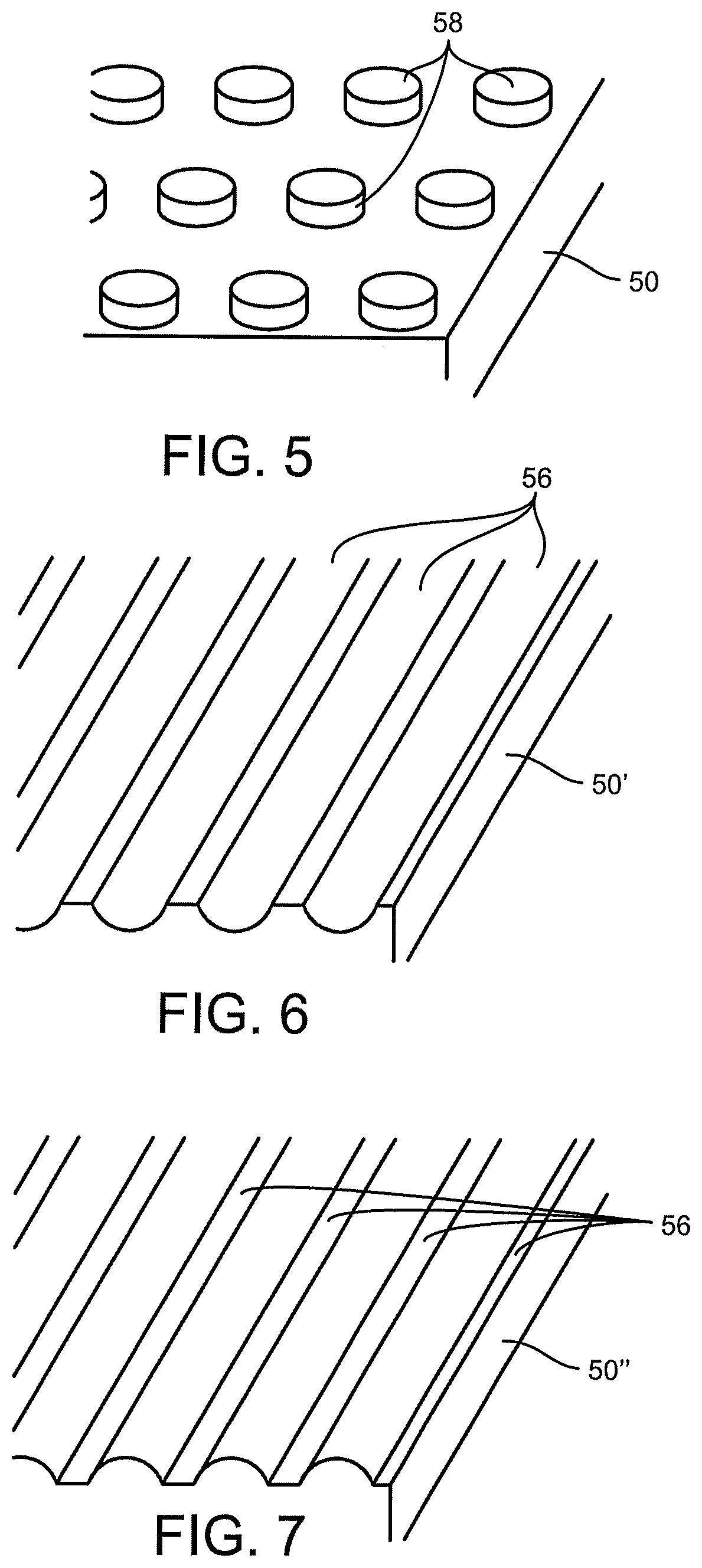
[0010] FIG. 5 is an illustration of an embodiment of a foam insulation board.
[0011] FIG. 6 is an illustration of another embodiment of a foam insulation board.
[0012] FIG. 7 is an illustration of yet another embodiment of a foam insulation board.
[0013] FIG. 8 is an illustration of still another embodiment of a foam insulation board.
SUMMARY OF THE INVENTION
[0014] A method for facilitating ventilation and/or drainage in a building wall, floor, and/or roof by the step of: placing a foam insulation board with an interior board face and an exterior board face, at least one board face having ventilation and/or drainage grooves and/or protrusions into the building wall, floor, and/or roof; providing vents in the building wall, floor, and/or roof adjacent end portions of the insulation board, whereby ventilation is facilitated within the wall, floor, and/or roof of the building by air moving through the vents, along the grooves and/or protrusions of the foam insulation board, and out of the vents, drainage of water is facilitated within the wall or the roof of the building by a pathway created by the grooves and/or protrusions, and moisture removal is facilitated by the passage of air during ventilation.
Description of the Invention
[0015] Referring to the figures, the ventilated and draining foam insulation panel for a wall, floor, and/or roof is illustrated.
[0016] FIG. 1 shows a wall 10, parts broken away for clarity (the invention is not limited to wall, as discussed below). Wall 10 shows frame 12 (having studs and plates) with a conventional interior cladding 11 (e.g., drywall, paneling), a conventional sheathing 14 (e.g., OSB, foam board, plywood), an optional, but preferred, a conventional moisture barrier 18 (e.g., house wrap), foam insulation panel 50, a veneer (or exterior cladding) 16, an vents 70.
[0017] FIG. 2 is a schematic illustration of an embodiment of a cross-section of a wall system 10 on a foundation 20. The wall system 10 generally includes: a frame 12, a sheathing 14 affixed to the frame 12, a foam insulation panel 50 (discussed in greater detail below) affixed over the sheathing 14, and a veneer 16 (e.g., brick, stucco, siding). Optionally, the wall system 10 may include a vapor barrier (e.g., house wrap), not shown, but conventionally located, for example, between the sheathing 14 and the foam insulation 50. FIG. 3 is a schematic illustration of an embodiment of a cross-section of a roof system 30. The roof system 30 generally includes: a frame 32 (e.g., rafters), a sheathing 34 (e.g., roof deck) affixed to the frame 32, a foam insulation panel 50 (discussed in greater detail below) affixed over the sheathing 34, and a veneer 36 (e.g., shingles). Optionally, the roof system 30 may also include a moisture barrier (e.g., tar paper), not shown, but conventionally located, for example, between the sheathing 34 and the foam insulation 50. FIG. 4 is a schematic illustration of an embodiment of a cross-section of a floor system 40 (e.g., an attic floor is illustrated). The floor system 40 generally includes: a frame 42 (e.g., joists), a sheathing 44 (e.g., subfloor) affixed to the frame 42, a foam insulation panel 50 (discussed in greater detail below) affixed over the sheathing 44, and, optionally, a veneer 46 (e.g., flooring). Optionally, the floor system 40 may also include a moisture barrier (e.g., house wrap), not shown, but conventionally located, for example, between the sheathing 44 and the foam insulation 50. The foregoing is not limiting on the invention, and those of ordinary skill will readily understand the application of the invention.
[0018] Hereinafter, the foam insulation panel (or foam panel) 50 will be discussed.
[0019] The foam insulation panel (or board) 50 facilitates ventilation, moisture removal, and drainage within the wall 10, floor 40, and/or roof 30 via a plurality of vertical grooves (or pathways formed by protrusions), discussed in greater detail below. These grooves (or pathways) allow air to move through the vents in the wall, floor, and/or roof systems, along the grooves (or pathways), and out of the vents, allow drainage of water by the grooves or pathways, and moisture removal by the passage of air during ventilation. Additionally, the foam insulation panel (or board) will impact the thermal insulation value (R) of the foam board and the wall 10, floor 40 or roof 30 systems.
[0020] The foam insulation board 50 has an interior board face 52 and an exterior board face 54 and at least one face has ventilation and/or drainage grooves 56 and/or protrusions 58, see FIGS. 5-7. The foam board 50 may have grooves 56 and/or protrusions 58 on both faces of the board, see FIGS. 1 and 8. The grooves 56 and/or protrusions 58 are used to create space to facilitate the removal of moisture. Additionally, the foam board 50 may have a thermal foil 60 affixed to, all or part of, he interior face, exterior face, or both, discussed below.
[0021] FIG. 5 illustrates one face of the foam board 50 with a plurality of protrusions 58 (e.g., cylindrical shown, but not so limited). FIG. 6 illustrates one face of board 50' with a plurality of concave grooves 56 (e.g., hemi-cylindrical, but not so limited). FIG. 7 illustrates one face of board 50'' with a plurality of convex grooves 56 (e.g., hemi-cylindrical, but not so limited). FIGS. 1 and 8 illustrate a foam board with grooves, on both sides of the foam board 50. In FIG. 1 the grooves on each face run in the generally horizontal and generally vertical directions. In FIG. 8, the grooves on each face run in one direction. In the foregoing description of the foam board 50, certain shapes of the protrusions or grooves are mentioned, but those shapes are non-limiting and any shape is possible, so long as the shape facilitates removal of moisture from within the wall.
[0022] The foam board 50 may have a density in the range of about 15-60 Kg/m.sup.3. The foam board 50 may have a groove depth (or the protrusion height) in the range of about 0.125-0.75 inches, preferably about 0.15-0.35 inches, most preferably about 0.25 inches. The foam board may have a thickness in a range of about 1-6 inches, preferably about 2-4 inches. The foam board may be any foam material. The foam board may be a closed cell foam. The foam board may have a moisture impervious and/or thermally impacting skin.
[0023] The thermal foil 60, one embodiment shown in FIG. 8, shows a cross-section of the foam board with a thermal foil on both sides thereof. The thermal foil 60 may be any thermal foil that can raise or lower the R value of the board and/or the wall, floor, or roof system. In one embodiment, the thermal foil 60 may be a reflective (e.g., metalized or aluminized) foil. In theory, the reflective foil may replenish the R value of the lost because of the grooves or channels placed in the foam board.
[0024] The vents 70 are conventional and may be located along the terminal ends of the foam board 50 so that moisture-laden air may flow through the vents and the grooves/protrustions of the foam board and out another vent.
[0025] In operation, ventilation is facilitated within the wall, floor, and/or roof of the building by air moving through the vents, along the grooves and/or protrusions of the foam insulation board, and out of the vents, drainage of water is facilitated within the wall or the roof of the building by a pathway created by the grooves and/or protrusions, and moisture removal is facilitated by the passage of air during ventilation.
[0026] The present invention may be embodied in other forms without departing from the spirit and the essential attributes thereof, and, accordingly, reference should be made to the appended claims, rather than to the foregoing specification, as indicating the scope of the invention.
* * * * *
D00000
D00001
D00002
D00003
XML
uspto.report is an independent third-party trademark research tool that is not affiliated, endorsed, or sponsored by the United States Patent and Trademark Office (USPTO) or any other governmental organization. The information provided by uspto.report is based on publicly available data at the time of writing and is intended for informational purposes only.
While we strive to provide accurate and up-to-date information, we do not guarantee the accuracy, completeness, reliability, or suitability of the information displayed on this site. The use of this site is at your own risk. Any reliance you place on such information is therefore strictly at your own risk.
All official trademark data, including owner information, should be verified by visiting the official USPTO website at www.uspto.gov. This site is not intended to replace professional legal advice and should not be used as a substitute for consulting with a legal professional who is knowledgeable about trademark law.