Acoustic Cell Separation Techniques and Processes
Lipkens; Bart ; et al.
U.S. patent application number 16/421459 was filed with the patent office on 2019-11-14 for acoustic cell separation techniques and processes. The applicant listed for this patent is FloDesign Sonics, Inc.. Invention is credited to Kedar C. Chitale, Rudolf Gilmanshin, Krishna N. Kumar, Bart Lipkens, Walter M. Presz, JR., Natalia Rodionova, Benjamin Ross-Johnsrud, Rui Tostoes, Ruan Zhang.
| Application Number | 20190345477 16/421459 |
| Document ID | / |
| Family ID | 68465212 |
| Filed Date | 2019-11-14 |


View All Diagrams
| United States Patent Application | 20190345477 |
| Kind Code | A1 |
| Lipkens; Bart ; et al. | November 14, 2019 |
Acoustic Cell Separation Techniques and Processes
Abstract
Beads with functionalized material applied to them are exposed to an acoustic field to trap, retain or pass the beads. The beads may include or be free of ferro magnetic material. The beads may be biocompatible or biodegradable for a host. The size of the beads may vary over a range, and/or be heterogenous or homogenous. The composition of the beads may include high, neutral or low acoustic contrast material. The chemistry of the functionalized material may be compatible with existing processes. The acoustic field may be generated, for example, in an acoustic angled wave device or in an acoustic fluidized bed.
| Inventors: | Lipkens; Bart; (Bloomfield, CT) ; Chitale; Kedar C.; (Vernon, CT) ; Kumar; Krishna N.; (Wilbraham, MA) ; Presz, JR.; Walter M.; (Wilbraham, MA) ; Zhang; Ruan; (Winchester, MA) ; Ross-Johnsrud; Benjamin; (Northampton, MA) ; Gilmanshin; Rudolf; (Framingham, MA) ; Rodionova; Natalia; (Framingham, MA) ; Tostoes; Rui; (Northampton, MA) | ||||||||||
| Applicant: |
|
||||||||||
|---|---|---|---|---|---|---|---|---|---|---|---|
| Family ID: | 68465212 | ||||||||||
| Appl. No.: | 16/421459 | ||||||||||
| Filed: | May 23, 2019 |
Related U.S. Patent Documents
| Application Number | Filing Date | Patent Number | ||
|---|---|---|---|---|
| 16010296 | Jun 15, 2018 | |||
| 16421459 | ||||
| 15916270 | Mar 8, 2018 | |||
| 16010296 | ||||
| 15586116 | May 3, 2017 | |||
| 15916270 | ||||
| 15788784 | Oct 19, 2017 | |||
| 15586116 | ||||
| 15942316 | Mar 30, 2018 | |||
| 15788784 | ||||
| 15613790 | Jun 5, 2017 | |||
| 15942316 | ||||
| 15143481 | Apr 29, 2016 | 9670477 | ||
| 15613790 | ||||
| 62675194 | May 23, 2018 | |||
| 62679012 | May 31, 2018 | |||
| 62520488 | Jun 15, 2017 | |||
| 62468895 | Mar 8, 2017 | |||
| 62330947 | May 3, 2016 | |||
| 62359182 | Jul 6, 2016 | |||
| 62374910 | Aug 15, 2016 | |||
| 62410312 | Oct 19, 2016 | |||
| 62479309 | Mar 30, 2017 | |||
| 62485229 | Apr 13, 2017 | |||
| 62316933 | Apr 1, 2016 | |||
| 62154690 | Apr 29, 2015 | |||
| Current U.S. Class: | 1/1 |
| Current CPC Class: | G01N 2015/149 20130101; C12N 13/00 20130101; B01L 2200/0652 20130101; B01L 2300/0867 20130101; G01N 2015/0053 20130101; A61M 1/3678 20140204; B01D 21/283 20130101; G01N 15/1484 20130101; A61M 1/3618 20140204; B01L 3/502761 20130101; B01L 3/50273 20130101; G01N 2015/1006 20130101; B01L 2400/0439 20130101; C12M 47/04 20130101; B01L 2400/0436 20130101; B01L 2300/0864 20130101 |
| International Class: | C12N 13/00 20060101 C12N013/00; B01D 21/28 20060101 B01D021/28; G01N 15/14 20060101 G01N015/14; A61M 1/36 20060101 A61M001/36; B01L 3/00 20060101 B01L003/00; C12M 1/00 20060101 C12M001/00 |
Claims
1. Material for use in a separation process, comprising: beads that are free of ferro-magnetic material; and a functionalized material on the beads for attracting a target biomaterial.
2. A system for separating material, comprising: a device for generating an acoustic field; a plurality of beads that include biomaterial bound to each bead, the beads being retained or passed upon being presented to the acoustic field.
3. The system of claim 2, further comprising a fluidized bed operative to house the beads.
4. The system of claim 2, further comprising an acoustic angled wave chamber operative to process a flow of fluid containing the beads.
5. The system of claim 2, wherein the beads comprise acoustic beads.
6. The system of claim 2, wherein at least some of the plurality of beads are composed with an affinity for one or more of CD3, CD4 or CD8 receptors.
7. A method for separating material, comprising: applying a functionalized material to a plurality of beads; exposing the beads to biomaterial with an affinity for the functionalized material to permit the biomaterial to bind to the beads; and exposing the beads to an acoustic field to retain or pass the beads.
8. The method of claim 7, further comprising employing a fluidized bed to house the beads.
9. The method of claim 7, further comprising employing an acoustic angled wave chamber to process a flow of fluid containing the beads.
10. The method of claim 7, wherein the beads comprise acoustic beads.
11. The method of claim 7, wherein at least some of the plurality of beads are composed with an affinity for one or more of CD3, CD4 or CD8 receptors.
Description
CROSS-REFERENCE TO RELATED APPLICATIONS
[0001] This application claims the benefit of U.S. Provisional Patent Application Ser. No. 62/675,194, filed on May 23, 2018, and claims the benefit of U.S. Provisional Patent Application Ser. No. 62/679,012, filed on May 31, 2018, and is a continuation-in-part of U.S. patent application Ser. No. 16/010,296, filed on Jun. 15, 2018, which claims the benefit of U.S. Provisional Patent Application Ser. No. 62/520,488, filed on Jun. 15, 2017, and which is a continuation-in-part of U.S. patent application Ser. No. 15/916,270, filed on Mar. 8, 2018, which claims the benefit of U.S. Provisional Patent Application Ser. No. 62/468,895, filed on Mar. 8, 2017. This application is also a continuation-in-part of U.S. patent application Ser. No. 15/586,116, filed on May 3, 2017, which claims the benefit of U.S. Provisional Patent Application Ser. No. 62/330,947, filed on May 3, 2016, and U.S. Provisional Patent Application Ser. No. 62/359,182, filed on Jul. 6, 2016, and U.S. Provisional Patent Application Ser. No. 62/374,910, filed on Aug. 15, 2016. This application is also a continuation-in-part of U.S. patent application Ser. No. 15/788,784, filed on Oct. 19, 2017, which claims the benefit of U.S. Provisional Patent Application Ser. No. 62/410,312, filed on Oct. 19, 2016. This application is a continuation-in-part of U.S. patent application Ser. No. 15/942,316, filed on Mar. 30, 2018, which claims the benefit of U.S. Provisional Patent Application Ser. No. 62/479,309, filed on Mar. 30, 2017; and U.S. Provisional Patent Application Ser. No. 62/485,229, filed on Apr. 13, 2017, and is a continuation-in-part of U.S. patent application Ser. No. 15/613,790, filed on Jun. 5, 2017, which is a divisional of U.S. patent application Ser. No. 15/143,481, filed on Apr. 29, 2016, now U.S. Pat. No. 9,670,477, issued on Jun. 6, 2017, which claims the benefit of U.S. Provisional Patent Application Ser. No. 62/316,933, filed on Apr. 1, 2016; and U.S. Provisional Patent Application Ser. No. 62/154,690, filed on Apr. 29, 2015. The entire disclosures of these applications are hereby fully incorporated herein by reference.
BACKGROUND
[0002] Separation of biomaterial has been applied in a variety of contexts. For example, separation techniques for separating proteins from other biomaterials are used in a number of analytical processes.
SUMMARY
[0003] Separation of biomaterials can be accomplished by functionalized material distributed in a fluid chamber that bind the specific target materials such as recombinant proteins and monoclonal antibodies or cells. The functionalized material, such as beads that are coated with an affinity protein, is trapped by nodes and/or anti-nodes of an acoustic standing wave. In this approach, the functionalized material is trapped without contact (without, for example, using mechanical channels, conduits, tweezers, etc.).
BRIEF DESCRIPTION OF THE DRAWINGS
[0004] The drawings are described in more detail below, with reference to the accompanying drawings, in which:
[0005] FIG. 1 is a diagram of a separation process using paramagnetic beads in a magnetic field;
[0006] FIG. 2 is a diagram of a separation process using acoustic beads in an acoustic field;
[0007] FIG. 3 is an image of CD3+ T-cell complexes with beads;
[0008] FIG. 4 is an image of beads without CD3- T-cells to demonstrate specificity of selection;
[0009] FIG. 5 is an image of heterogenous beads available with streptavidin and biotin conjugates;
[0010] FIG. 6 is an image of homogenous agarose beads;
[0011] FIG. 7 is a photograph of a miniature acoustic system for processing beads;
[0012] FIG. 8 is a photograph of a separation result;
[0013] FIG. 9 is a diagram of an affinity technique that may be used with beads;
[0014] FIGS. 10, 11 and 12 are microphotographs of streptevidin-conjugated and biotin-conjugated beads that form complexes with each other;
[0015] FIG. 13 is a microphotograph of a cell suspension with identification of an Erythrocyte, a Dendritic cell and a T cell;
[0016] FIG. 14 is a microphotograph of a bright field image of cells;
[0017] FIG. 15 is a microphotograph of a bright field image of green fluorescence of anti-CD4 antibodies bound to cells;
[0018] FIG. 16 is a microphotograph of a bright field image of cells;
[0019] FIG. 17 is a microphotograph of a bright field image of magenta fluorescence of anti-CD4 antibodies bound to cells;
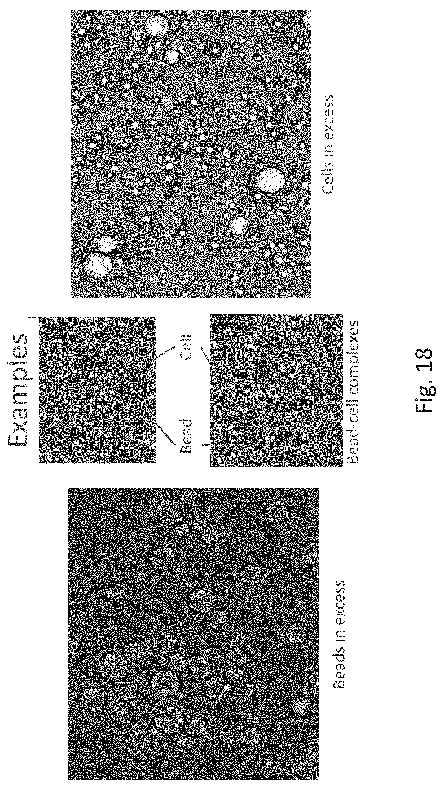
[0020] FIG. 18 is a series of microphotographs illustrate examples of bead-cell complexes in environments with an excess of beads and with an excess of cells;
[0021] FIG. 19 is a diagram of example activation chemistries for affinity binding;
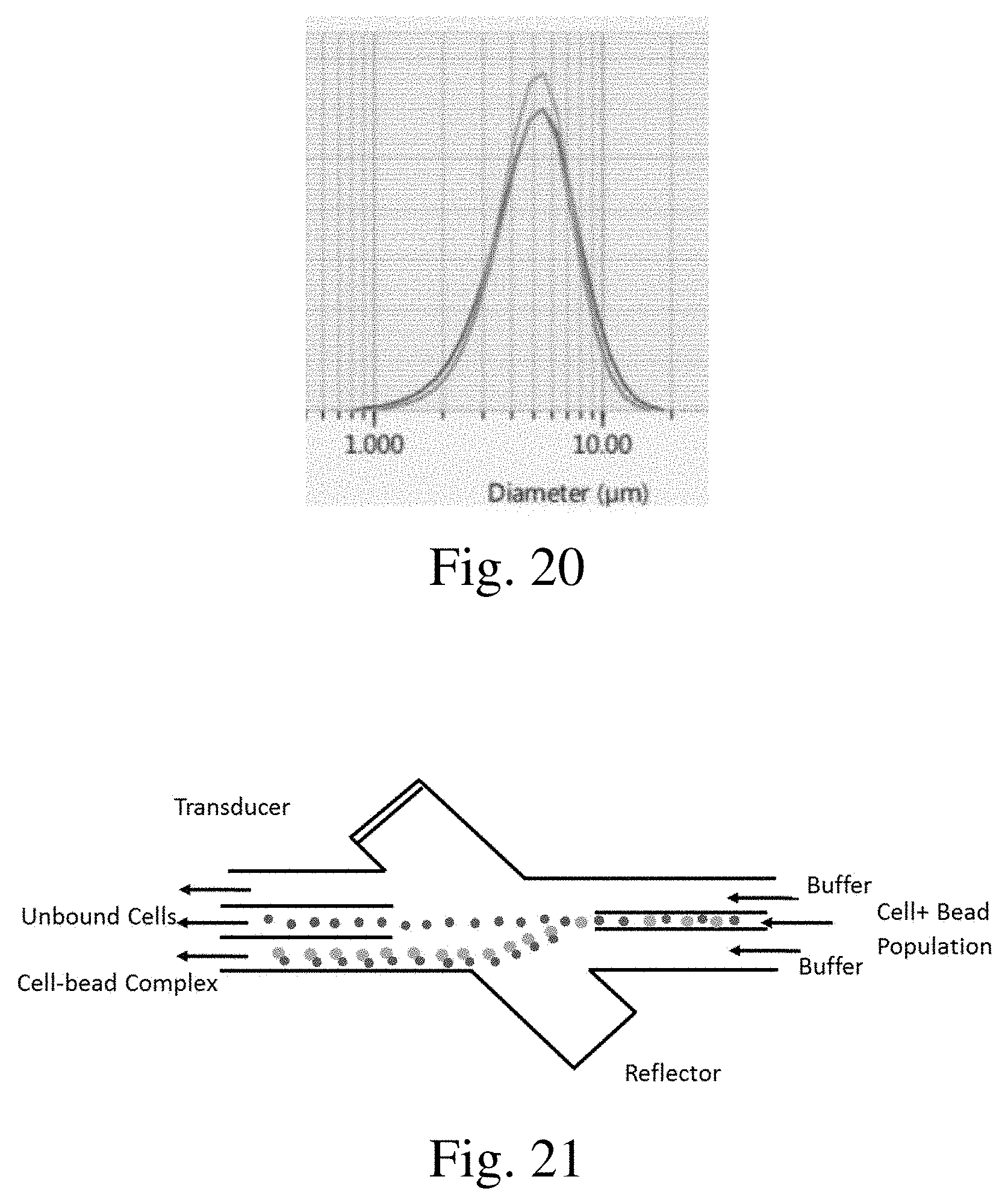
[0022] FIG. 20 is a graph showing bead size distribution with acoustic angled wave selection;
[0023] FIG. 21 is a diagram of an acoustic angled wave device showing bulk separation by size;
[0024] FIG. 22 is a diagram of an acoustic fluidized bed device for affinity cell selection; and
[0025] FIG. 23 is a set of graphs illustrating cytometer results from an acoustic affinity cell selection device.
DETAILED DESCRIPTION
[0026] The affinity separation of biological materials, such as proteins or cells, is accomplished through the use of a ligand that is covalently bonded to a surface, such as a microbead, interacts with the protein or cell such that the protein or cell is bound to the ligand on the microbead.
[0027] A ligand is a substance that forms a complex with the biomolecules. With protein-ligand binding, the ligand is usually a molecule which produces a signal by binding to a site on a target protein the binding typically results in a change of confirmation of target protein. The ligand can be a small molecule, ion, or protein which binds to the protein material. The relationship between ligand and binding partner is a function of charge, hydrophobicity, and molecular structure. Binding occurs by intermolecular forces such as ionic bonds, hydrogen bonds and van der Waals forces. The Association of docking is actually reversible through disassociation. Measurably irreversible covalent bonds between the ligand and target molecule is typical in biological systems.
[0028] A ligand that can bind to a receptor, alter the function of the receptor, and trigger a physiological response is called an agonist for the receptor. Agonist binding to receptor can be characterized both in terms of how much physiological response can be triggered and in terms of the concentration of the agonist that is required to produce the physiological response. High affinity ligand binding implies that the relatively low concentration of the ligand is adequate to maximally occupy a ligand--binding site and trigger a physiological response. The lower the K.sub.i level is, the more likely there will be a chemical reaction between the pending and the receptive antigen. Low--affinity binding (high K.sub.i level) implies that a relatively high concentration of the ligand is required before the binding site is maximally occupy and the maximum physiological response to the ligand is achieved. Bivalent ligands consist of two connected molecules as ligands, and are used in scientific research to detect receptor timers and to investigate the properties.
[0029] The T cell receptor, or TCR, is a molecule found on the surface of T cells or T lymphocytes, that is responsible for recognizing fragments of antigen as peptides bound to major histocompatibility complex (MHC) molecules. The binding between TCR and antigen peptides is of relatively low affinity and is degenerative.
[0030] Referring to FIG. 1, paramagnetic beads, such as iron or ferro-magnetic beads sold under the name Dynabeads, have been used to achieve affinity extraction. The magnetic beads, coated with a functionalized material, bind to biological targets in complex mixtures to permit the target material to be separated out of the complex mixture using a magnetic field. The beads carry molecules for affine binding various targets with high specificity. The beads are injected into the complex mixture and incubated to bind the targets. The beads are extracted by a magnet together with the targets attached to the beads.
[0031] Micro sized beads are available, such as, e.g., Dynabeads, which are on the order of 4.5 .mu.m in size. Nano sized beads may be used, such as, e.g., Myltenyi, which are on the order of 50 nm in size. Some of the affine molecules that may be used include antibodies, aptamers, oligonucleotides and receptors, among others. The targets for the affinity binding may include biomolecules, cells, exosomes, drugs, etc.
[0032] Referring to FIG. 2, beads with high acoustic contrast and affinity chemistry are illustrated. These acoustic beads can be used in exactly the same way as magnetic beads with regard to having functionalized material coatings or composition for affinity binding. The acoustic beads are designed to be extracted from a complex mixture or fluid with an acoustic field. The acoustic beads can be directly used in all the applications developed in cell manufacturing, biochemistry, diagnostics, sensors, etc. that use magnetic beads.
[0033] The acoustic beads can use the same surface and affinity chemistry as is used with magnetic beads. This ease of substitution of acoustic beads for magnetic beads has many advantages, including simplifying approval for applications, as well as simplifying the applications.
[0034] The acoustic beads can be made biocompatible. Such beads can be produced in different sizes, which permits continuous separation based on size in a size differentiating acoustic field, such as may be provided with an angled-field fractionation technology. The acoustic beads can be combined with an enclosed acoustics-based system, leading to a continuous end-to-end cycle for therapeutic cell manufacturing. This functionality provides an alternative to magnetic bead extraction, while preserving use of currently existing affinity chemistry, which can be directly transferred to the acoustic beads. The acoustic beads may be a consumable product in the separation operation.
[0035] In an example, a proof of concept trial was made using the published Memorial Sloan Kettering Cancer Center (MSKCC) protocol for extraction of CD3+ T cells from patient's blood. In the trial, paramagnetic beads were used, and the magnetic field is replaced with an acoustic field. The process of extracting CD3+ T cells from patient's blood is an integral part of manufacturing CAR (chimeric antigen receptor) T cells. Current processes are based on commercially available CD3 Dynabeads. In the trial, efforts were made to minimize the protocol differences, including performing the experiments in culture broth, rather than blood. The difference is considered reduced since several steps in CAR T cell manufacturing work from broth. The solvent density was increased to make T cells "acoustically invisible," or not as susceptible to an acoustic field. The small size of the Dynabeads may provide an acoustic contrast that is similar to the cells, thus making separation tolerances smaller. The trial employed Jurkat CD3+ and CD3- T cell lines as models. The CD3- cells were employed as a control for non-specific trapping.
[0036] Referring now to FIGS. 3 and 4, images of results of the trial are shown. The cell suspensions were incubated with CD3 Dynabeads, which bound CD3+ cells. The mixture was passed through the acoustic system, which trapped the magnetic beads (with or without cells). The collected cells were successfully growing in culture. The images in FIGS. 3 and 4 are obtained with overlap of bright field images with fluorescence images. The beads are black with slight reddish autofluorescence. The live cells are fluorescent red. The bead diameter is 4.5 microns. FIG. 3 shows CD3+ T-cell complexes with beads, which demonstrates the efficiency of the technique. FIG. 4 shows that no CD3- T-cells have been extracted, which demonstrates the specificity and selectivity of the technique.
[0037] Referring now to FIGS. 5 and 6, results of a trial with acoustic beads is shown. In this trial, agarose beads were used as the acoustic beads. These beads are available off-shelf from several manufacturers, and are not paramagnetic or have little to none iron or ferro magnetic content. Some agarose beads have surface modifications that simplify antibody attachment. They are also composed of biocompatible material, which can be important for therapeutic solutions. FIG. 5 shows ABTBeads, which are relatively inexpensive, heterogeneous (20-150 .mu.m), off-shelf beads, which are available with streptavidin and biotin conjugates. FIG. 6 shows CellMosaic agarose beads, which tend to be relatively expensive, homogeneous (20-40 .mu.m), and can be configured with any modification by order.
[0038] The acoustic beads can be trapped in an acoustic field, such as a multi-dimensional acoustic standing wave. Referring to FIG. 7, a miniature acoustic system developed for acoustic applications is shown, which is used for trapping the acoustic beads. The smaller size of the system contributes to reducing the need for larger amounts of expensive reagents and permits processing of small volume samples.
[0039] Referring to FIG. 8, CellMosaic agarose beads escaped (left tube) and trapped (right) in the acoustic system are shown. The acoustic system trapping efficiency can be 90%+.
[0040] Referring to FIG. 9, a flexible approach to activating the acoustic beads is illustrated. In this approach, antibodies are attached to agarose beads using a streptavidin-biotin complex. The complex is widely used in biochemistry, and very stable. Agarose beads with conjugated streptavidin are available commercially as are antibody-biotin conjugates.
[0041] The functionality of streptavidin-beads & biotin-beads was evaluated. Referring to FIGS. 10-12, streptevidin-conjugated and biotin-conjugated beads are shown to form complexes with each other, as expected, upon mixing,
[0042] It may be desirable to obtain independent isolation of CD4+ and CD8+ ("helper" and "killer" T cells, respectively) from suspensions and mixing them in desired ratios with a view toward efficient therapy. Toward this end, acoustic beads with affinity for CD4 and CD8 receptors can be provided. A trial to obtain an example was performed with cell suspensions prepared from mice spleens. Referring to FIG. 13, identification of an Erythrocyte, a Dendritic cell and a T cell is provided. About 20 million (M) and 18M CD4+ and CD8+ T-cells, respectively, have been isolated from 4 spleens using Invitrogen depletion kits. Both cell lines can grow, and both CD4 and CD8 T-cells are about 8.2-8.6 .mu.m.
[0043] In this trial, CD4+ and CD8+ isolated cells were verified immunologically. Referring to FIGS. 14 and 15, verification of the presence of CD4 receptors is obtained. Alexa488 anti-CD4 antibodies are used to estimate the amount of isolated CD4 T-cells after purification from mouse spleens. FIG. 14 shows a bright field image with small circles being the cells in focal plane. FIG. 15 shows fluorescence of anti-CD4 antibodies bound to the cells. FIG. 16 shows a bright field image with small circles being the cells in focal plane. FIG. 17 shows fluorescence of anti-CD4 antibodies bound to the cells. The different colors of green and magenta in FIGS. 15 and 17, respectively, can allow multiplex analysis of results, e.g., a CD4/CD8 ratio.
[0044] Referring now to FIG. 18, results of the trial are shown where Streptavidin-conjugated agarose beads were employed with biotin-conjugated anti-CD3 antibodies and CD3+ Jurkat T-cells. The affinity combinations of beads and cells is clearly illustrated. The beads can be separated out in an acoustic field to extract the cells from the mixture.
[0045] Proof-of-concept and validation of performance has been shown using acoustic affinity beads in an acoustic system. The disclosed methods and systems permit the use of off-shelf reagents, and currently available acoustic systems. The affinities can target any type of desired T cells or markers including CD3+, CD4+, CD8+. The acoustic beads can have a high, neutral or low contrast factor, which can affect how the beads respond to an acoustic field, for example being urged toward an acoustic node or antinode, or passing through the field.
[0046] The beads may be composed of various materials and combinations, which permits development of optimal chemistry with acoustic performance and biocompatibility. Some examples of bead constructs are provided in U.S. patent application Ser. No. 16/208,512, filed Dec. 3, 2018, the entire disclosure of which is incorporated herein by reference. The beads may be processed for isolation, sorting or any other function useful in a separation process. When used with a tuned acoustic system, the performance of specifically designed acoustic beads can match or exceed that of paramagnetic beads.
[0047] Existing chemistries may be used with the acoustic beads, and in conjunction with specifications of size and structure homogeneity to achieve desired results for acoustic and for isolation performance. The beads may be composed of composite constructs to advance acoustic efficiency. The acoustic system provides flexibility to manage small sizes, with heat management, and the use of fluidics to obtain results that are not possible with paramagnetic beads alone. The biocompatibility and/or biodegradability of the acoustic beads and simplified processing permits integration with existing hardware for CAR T cell manufacturing. The affinity acoustic beads can be used in a number of environments, including model environments such as, e.g., animal blood spiked with target cells and murine spleen extracts. The acoustic beads may thus be used in collaboration with existing systems, and may be designed and manufactured for target applications. The beads may be provided with a core that is acoustically active or neutral, and the bead themselves may be configured for high, neutral or low acoustic contrast. The size of the beads may be configured for separation and affinity in combination, for example a certain sized bead may include functionalized material to target a certain biomaterial, while another sized bead, may be functionalized to target another biomaterial, each of which can be separated simultaneously and continuously in a closed or flowing system. The beads can be designed to be of a homogeneous size distribution within a narrow or relatively broad range. Various affinity chemistries may be used, including streptavidin-biotin complex and immunoglobulin or aptamer. The beads may be designed for ease of manufacturability and/or for shelf-life. The beads may be used with approved chemistries, so that they may readily be integrated into known systems that use approved chemistries.
[0048] Referring to FIG. 19, an illustration of example activation chemistries is shown. The activation chemistries illustrated are applicable to the acoustic affinity beads described herein.
[0049] Referring to FIG. 20, a graph illustrating a size distribution of separated particles is shown. The distribution range is relatively small or tight, indicating the efficacy of the separation technique using the acoustic angled wave device.
[0050] Referring to FIG. 21, a diagram of an operating mode of an acoustic angled wave device is illustrated. The larger size cell-bead complexes experience greater deflection passing through the angled acoustic wave than the cells alone, leading to the separation of the two populations. This technique can be applied in an affinity environment, where target material, such as specific cell types, bind to a functionalized bead to form a cell-bead complex that can be separated from the population using the acoustic angled wave device.
[0051] Referring to FIG. 22, a diagram of an acoustic fluidized bed device is illustrated. The fluidized bed is composed of functionalized beads that bind to the target material as the target material is flowed through the fluidized bed. The beads are retained by the acoustic field in the column, thereby retaining in the column the target material attached to the beads. The bead-target material complexes are distinguished by the acoustic field from other materials flowed through the fluidized bed. The distinguishing characteristics may be dimensional, e.g. size or diameter, and/or may be based on acoustic contrast factor, density, compressibility, or any acoustically responsive characteristic that can differentiate components in the fluidized bed. The fluidized bed can be operated in a positive or negative selection mode, meaning that the desired product may be captured by attachment to the beads, or may be free to pass through the acoustic field to be recovered.
[0052] Referring to FIG. 23, cytometer result graphs illustrate the efficacy of separation techniques using acoustic processing. In the example for the results illustrated in FIG. 23, TCR+ cells are removed from a mixed population of TCR+ and TCR- cells. As illustrated on the left-hand side graphs, the TCR+ population prior to acoustic processing is significant. The right-hand side graphs show a significant reduction in the TCR+ population following acoustic processing. The graphs illustrated in FIG. 23 are derived from an acoustic fluidized bed. Similar results are obtainable using an acoustic angled wave device.
[0053] The methods, systems, and devices discussed above are examples. Various configurations may omit, substitute, or add various procedures or components as appropriate. For instance, in alternative configurations, the methods may be performed in an order different from that described, and that various steps may be added, omitted, or combined. Also, features described with respect to certain configurations may be combined in various other configurations. Different aspects and elements of the configurations may be combined in a similar manner. Also, technology evolves and, thus, many of the elements are examples and do not limit the scope of the disclosure or claims.
[0054] Specific details are given in the description to provide a thorough understanding of example configurations (including implementations). However, configurations may be practiced without these specific details. For example, well-known processes, structures, and techniques have been shown without unnecessary detail to avoid obscuring the configurations. This description provides example configurations only, and does not limit the scope, applicability, or configurations of the claims. Rather, the preceding description of the configurations provides a description for implementing described techniques. Various changes may be made in the function and arrangement of elements without departing from the spirit or scope of the disclosure.
[0055] Also, configurations may be described as a process that is depicted as a flow diagram or block diagram. Although each may describe the operations as a sequential process, many of the operations can be performed in parallel or concurrently. In addition, the order of the operations may be rearranged. A process may have additional stages or functions not included in the figure.
[0056] Having described several example configurations, various modifications, alternative constructions, and equivalents may be used without departing from the spirit of the disclosure. For example, the above elements may be components of a larger system, wherein other structures or processes may take precedence over or otherwise modify the application of the invention. Also, a number of operations may be undertaken before, during, or after the above elements are considered. Accordingly, the above description does not bound the scope of the claims.
* * * * *
D00000
D00001
D00002
D00003
D00004
D00005
D00006
D00007
D00008
D00009
D00010
D00011
D00012
D00013

D00014
D00015

D00016

XML
uspto.report is an independent third-party trademark research tool that is not affiliated, endorsed, or sponsored by the United States Patent and Trademark Office (USPTO) or any other governmental organization. The information provided by uspto.report is based on publicly available data at the time of writing and is intended for informational purposes only.
While we strive to provide accurate and up-to-date information, we do not guarantee the accuracy, completeness, reliability, or suitability of the information displayed on this site. The use of this site is at your own risk. Any reliance you place on such information is therefore strictly at your own risk.
All official trademark data, including owner information, should be verified by visiting the official USPTO website at www.uspto.gov. This site is not intended to replace professional legal advice and should not be used as a substitute for consulting with a legal professional who is knowledgeable about trademark law.