Rail Vehicle
REN; Lin ; et al.
U.S. patent application number 16/335208 was filed with the patent office on 2019-11-14 for rail vehicle. The applicant listed for this patent is BYD COMPANY LIMITED. Invention is credited to Junjie LIU, Fanghong PENG, Lin REN, Hao ZENG.
| Application Number | 20190344810 16/335208 |
| Document ID | / |
| Family ID | 61689322 |
| Filed Date | 2019-11-14 |


View All Diagrams
| United States Patent Application | 20190344810 |
| Kind Code | A1 |
| REN; Lin ; et al. | November 14, 2019 |
RAIL VEHICLE
Abstract
The present disclosure discloses a rail vehicle. The rail vehicle includes: a bogie, where the bogie has a straddle recess suitable for straddling a rail; and a vehicle body, where the vehicle body is connected to the bogie and pulled by the bogie to travel along the rail, and the vehicle body includes a plurality of compartments hinged sequentially along a length direction of the rail; and in the length direction of the rail, a surface of a compartment at at least one end of the vehicle body and facing away from an adjacent compartment is provided with an escape door that can be opened and closed. The rail vehicle according to these embodiments of the present disclosure facilitates optimization the structure of an escape passage, reduction in costs, reduction in occupied space and the weight borne by the rail, and improvement in stability.
| Inventors: | REN; Lin; (Shenzhen, CN) ; ZENG; Hao; (Shenzhen, CN) ; LIU; Junjie; (Shenzhen, CN) ; PENG; Fanghong; (Shenzhen, CN) | ||||||||||
| Applicant: |
|
||||||||||
|---|---|---|---|---|---|---|---|---|---|---|---|
| Family ID: | 61689322 | ||||||||||
| Appl. No.: | 16/335208 | ||||||||||
| Filed: | February 28, 2017 | ||||||||||
| PCT Filed: | February 28, 2017 | ||||||||||
| PCT NO: | PCT/CN2017/075214 | ||||||||||
| 371 Date: | March 20, 2019 |
| Current U.S. Class: | 1/1 |
| Current CPC Class: | B61F 5/00 20130101; B61D 19/023 20130101; B61F 9/00 20130101; B61B 13/04 20130101; B61F 3/00 20130101; B61F 5/52 20130101 |
| International Class: | B61F 3/00 20060101 B61F003/00; B61B 13/04 20060101 B61B013/04; B61D 19/02 20060101 B61D019/02; B61F 9/00 20060101 B61F009/00; B61F 5/52 20060101 B61F005/52 |
Foreign Application Data
| Date | Code | Application Number |
|---|---|---|
| Sep 21, 2016 | CN | 201610836631.6 |
| Sep 21, 2016 | CN | 201610840206.4 |
Claims
1. A rail vehicle, comprising: a bogie a straddle recess suitable for straddling a rail; and a vehicle body comprising a plurality of compartments hinged sequentially along the rail lengthwise, wherein the vehicle body is connected to the bogie and pulled by the bogie to travel along the rail.
2. The rail vehicle according to claim 1, further comprising an escape door that is openable and on a surface of a compartment at at least one end of the vehicle body, wherein the surface is along the rail lengthwise and facing away from an adjacent compartment.
3. The rail vehicle according to claim 2, wherein the escape door comprises a first end and a second end, the first end of the escape door is pivotably mounted onto the corresponding compartment, and the second end of the escape door tilts downward and stretches into the rail when the escape door is opened.
4. The rail vehicle according to claim 1, wherein the escape door has a slide rail on an inner surface of the escape door.
5. The rail vehicle according to claim 1, wherein the vehicle body comprises an escape port and an escape cover plate, the escape port is disposed on an inner floor of the compartment at the at least one end of the vehicle body, and the escape cover plate collaborates with the escape door and is disposed on the inner floor of the compartment at the at least one end of the vehicle body for the escape cover plate to open and close the escape port.
6. The rail vehicle according to claim 5, wherein the escape port has an escape ladder leading to an escape passage, and the vehicle body comprises a stretching/retraction driving device for stretching or retracting the escape ladder.
7. The rail vehicle according to claim 1, wherein the bogie comprises: a bogie frame, wherein the straddle recess is disposed on the bogie frame; a first running wheel and a second running wheel pivotably mounted onto the bogie frame respectively and coaxially spaced apart; and a driving device, wherein the driving device is mounted onto the bogie frame and is located between the first running wheel and the second running wheel, and the driving device drives the first running wheel and the second running wheel.
8. The rail vehicle according to claim 1, wherein the bogie comprises: a bogie frame, wherein the straddle recess is disposed on the bogie frame; a first running wheel and a second running wheel pivotably mounted onto the bogie frame respectively and coaxially spaced apart; a third running wheel and a fourth running wheel pivotably mounted onto the bogie frame respectively and coaxially spaced apart, wherein the third running wheel and the first running wheel are spaced apart along the rail lengthwise, and the fourth running wheel and the second running wheel are spaced apart along the rail; and a driving device mounted onto the bogie frame, wherein the driving device is located between the first running wheel and the second running wheel and/or between the third running wheel and the fourth running wheel, and the driving device drives the first running wheel and the second running wheel and/or the third running wheel and the fourth running wheel.
9. The rail vehicle according to claim 8, wherein the first running wheel and the second running wheel are connected by using a first connection shaft, the driving device is in transmission connection with the first connection shaft and/or the third running wheel and the fourth running wheel are connected by using a second connection shaft, the driving device is in transmission connection with the second connection shaft.
10. The rail vehicle according to claim 8, wherein the driving device comprises a first driving device and/or a second driving device, wherein the first driving device is located between the first running wheel and the second running wheel, the first driving device drives the first running wheel and the second running wheel, the first driving device is closer to the first running wheel than the second running wheel; and/or the second driving device is located between the third running wheel and the fourth running wheel, the second driving device drives the third running wheel and the fourth running wheel, and the second driving device is closer to the fourth running wheel than the third running wheel.
11. The rail vehicle according to claim 7, wherein the bogie comprises: a first horizontal wheel pivotably mounted onto the bogie frame and suitable for fitting in on a first side surface of the rail; and a second horizontal wheel pivotably mounted onto the bogie frame and suitable for fitting in on a second side surface of the rail.
12. The rail vehicle according to claim 11, wherein the bogie comprises: a first horizontal safety wheel connected to the first horizontal wheel and moving in synchronization with the first horizontal wheel, and a second horizontal safety wheel connected to the second horizontal wheel and moving in synchronization with the second horizontal wheel, wherein the outer diameter of the first horizontal safety wheel is less than the outer diameter of the first horizontal wheel, and the outer diameter of the second horizontal safety wheel is less than the outer diameter of the second horizontal wheel.
13. The rail vehicle according to claim 11, wherein the first horizontal wheel is suitable for fitting in on one outer side surface of the rail, and the second horizontal wheel is suitable for fitting in on another outer side surface of the rail.
14. The rail vehicle according to claim 11, wherein the first horizontal wheel is suitable for fitting in on one inner side surface of the rail, and the second horizontal wheel is suitable for fitting in on another inner side surface of the rail.
15. The rail vehicle according to claim 11, wherein the first horizontal wheel and the second horizontal wheel are located at a same height.
16. The rail vehicle according to claim 11, wherein the first horizontal wheel includes a plurality of first horizontal wheels spaced apart and coaxially disposed vertically, and the second horizontal wheel includes a plurality of second horizontal wheels spaced apart and coaxially disposed vertically.
17. The rail vehicle according to claim 11, wherein the first horizontal wheel includes a plurality of first horizontal wheels spaced apart along a vertical direction and the rail lengthwise respectively, and the second horizontal wheel includes a plurality of second horizontal wheels spaced apart along the vertical direction and the rail lengthwise respectively.
18. The rail vehicle according to claim 11, wherein the first horizontal wheel includes a plurality of first horizontal wheels suitable for respectively fitting in on one outer side surface and one inner side surface of the rail, and the second horizontal wheel includes a plurality of second horizontal wheels suitable for respectively fitting in on another outer side surface and another inner side surface of the rail.
19. The rail vehicle according to claim 14, wherein the first horizontal wheel suitable for fitting in on the one inner side surface of the rail and the second horizontal wheel suitable for fitting in on the another inner side surface of the rail are located at different heights.
20. The rail vehicle according to claim 11, wherein the first horizontal wheel includes two first horizontal wheels spaced apart along the rail lengthwise, the second horizontal wheel includes two second horizontal wheels spaced apart along the rail lengthwise, the central axes of the two first horizontal wheels and the central axes of the two second horizontal wheels are respectively located at four vertices of a rectangle in a horizontal plane, and the rectangle is symmetrical with respect to the center of the bogie frame.
Description
CROSS-REFERENCE TO RELATED APPLICATIONS
[0001] This application is based on and claims priority to Chinese Patent Application No. 201610836631.6, filed on Sep. 21, 2016 and Chinese Patent Application No. 201610840206.4, filed on Sep. 21, 2016, both of which are incorporated herein by reference in their entireties.
FIELD
[0002] The present disclosure relates to the field of transport technologies, and specifically to a rail vehicle.
BACKGROUND
[0003] A rail transport system, such as a straddle-type monorail train, may inevitably have emergency stop because of a fault or other factors during actual travelling. To facilitate evacuation of passengers in an emergency, the straddle-type monorail train in the related art is provided with an independent escape passage. Specifically, by additionally providing a frame on a rail, the frame is usually connected to a side of the rail and protrudes outward, and then a floor is laid on the frame to form a passage for evacuating passengers.
[0004] The inventors of this application have found, through a large quantity of researches and experiments, that disadvantages, such as high costs, large occupied space, and a hidden danger of stability, existing in the straddle-type monorail train provided with an escape passage in the related art are just caused by the structure of the foregoing escape passage. Specific reasons are as follows:
[0005] Since the frame and the floor laid on the frame are both additional added structures independent of the rail, and a specific location of a rail vehicle in an emergency during travelling is unpredictable, the escape passage of this structure needs to be additionally disposed in the entire length direction of the rail (except platforms). The amount of work is enormous, which greatly increases the costs. Moreover, the frame and the floor are located at the side of the rail, which is equivalent to a portion additionally extending in the width direction of the rail and takes up a lot of space. In addition, the frame and the floor have a certain weight. Regardless of whether the rail vehicle is in an emergency, the frame and the floor are both built on the rail, that is, even if the rail vehicle is travelling normally, the rail still needs to bear the weight of the frame and the floor, thereby increasing the weight borne by the rail, which has an adverse effect on the stability of the rail.
SUMMARY
[0006] An objective of the present disclosure is to at least resolve one of the foregoing technical problems in the related art to some extent.
[0007] To achieve the foregoing objective, according to an embodiment of the present disclosure, a rail vehicle is provided. The rail vehicle includes: bogies, wherein the bogie has a straddle recess suitable for straddling a rail; and a vehicle body, wherein the vehicle body is connected to the bogie and pulled by the bogie to travel along the rail, and the vehicle body includes a plurality of compartments hinged sequentially along a length direction of the rail.
[0008] The rail vehicle according to this embodiment of the present disclosure facilitates optimization of the structure of an escape passage, reduction in costs, reduction in occupied space and the weight borne by the rail, and improvement in stability.
[0009] Additionally, the rail vehicle according to this embodiment of the present disclosure may further have the following additional technical characteristics:
[0010] According to an embodiment of the present disclosure, in the length direction of the rail, a surface of a compartment at at least one end of the vehicle body and facing away from an adjacent compartment is provided with an escape door that can be opened and closed.
[0011] According to an embodiment of the present disclosure, a first end of the escape door is flippably and pivotably mounted onto the corresponding compartment, and a second end of the escape door tilts downward and is embedded in the rail when the escape door is opened.
[0012] According to an embodiment of the present disclosure, an inner surface of the escape door is provided with a slide rail.
[0013] According to an embodiment of the present disclosure, the vehicle body further includes an escape port and an escape cover plate. The escape port is disposed on an inner floor of the compartment at the at least one end, and the escape cover plate collaborates with the escape door and can be disposed on the inner floor of the compartment at the at least one end to enable the escape cover plate to open and close the escape port.
[0014] According to an embodiment of the present disclosure, an escape ladder leading to the rail is disposed in the escape port.
[0015] According to an embodiment of the present disclosure, the vehicle body has a stretching/retraction driving device used to drive stretching/retraction of the escape ladder.
[0016] According to an embodiment of the present disclosure, the bogie includes: a bogie frame, where the straddle recess is disposed on the bogie frame; a first running wheel and a second running wheel, wherein the first running wheel and the second running wheel are pivotably mounted onto the bogie frame respectively and are coaxially spaced apart; and a driving device, wherein the driving device is mounted onto the bogie frame and is located between the first running wheel and the second running wheel, and the first running wheel and the second running wheel are driven by the driving device.
[0017] According to an embodiment of the present disclosure, the bogie includes: a bogie frame, where the straddle recess is disposed on the bogie frame; a first running wheel and a second running wheel, where the first running wheel and the second running wheel are pivotably mounted onto the bogie frame respectively and are coaxially spaced apart; a third running wheel and a fourth running wheel, where the third running wheel and the fourth running wheel are pivotably mounted onto the bogie frame respectively and are coaxially spaced apart, the third running wheel and the first running wheel are spaced apart in the length direction of the rail, and the fourth running wheel and the second running wheel are spaced apart in the length direction of the rail; and a driving device, where the driving device is mounted onto the bogie frame, the driving device is located between the first running wheel and the second running wheel and/or the driving device is located between the third running wheel and the fourth running wheel, and the first running wheel and the second running wheel are driven by the driving device and/or the third running wheel and the fourth running wheel are driven by the driving device.
[0018] According to an embodiment of the present disclosure, the first running wheel and the second running wheel are connected by using a first connection shaft, and/or the third running wheel and the fourth running wheel are connected by using a second connection shaft; and the driving device is in transmission connection to the first connection shaft and/or the second connection shaft.
[0019] According to an embodiment of the present disclosure, the driving device includes a first driving device and a second driving device, where the first driving device is located between the first running wheel and the second running wheel, and the first running wheel and the second running wheel are driven by the first driving device; the second driving device is located between the third running wheel and the fourth running wheel, and the third running wheel and the fourth running wheel are driven by the second driving device; and the first driving device is closer to the first running wheel than the second running wheel, and/or the second driving device is closer to the fourth running wheel than the third running wheel.
[0020] According to an embodiment of the present disclosure, the bogie further includes: a first horizontal wheel, where the first horizontal wheel is pivotably mounted onto the bogie frame and is suitable for fitting in on a first side surface of the rail; and a second horizontal wheel, where the second horizontal wheel is pivotably mounted onto the bogie frame and is suitable for fitting in on a second side surface of the rail.
[0021] According to an embodiment of the present disclosure, the bogie further includes: a first horizontal safety wheel connected to the first horizontal wheel and moving in synchronization with the first horizontal wheel, and a second horizontal safety wheel connected to the second horizontal wheel and moving in synchronization with the second horizontal wheel. The outer diameter of the first horizontal safety wheel is less than the outer diameter of the first horizontal wheel, and the outer diameter of the second horizontal safety wheel is less than the outer diameter of the second horizontal wheel.
[0022] According to an embodiment of the present disclosure, the first horizontal wheel and the second horizontal wheel are located at a same height in an up and down direction.
[0023] According to an embodiment of the present disclosure, there is a plurality of first horizontal wheels spaced apart and coaxially disposed along an up and down direction, and there is a plurality of second horizontal wheels spaced apart and coaxially disposed along the up and down direction.
[0024] According to an embodiment of the present disclosure, there is a plurality of first horizontal wheels spaced apart along an up and down direction and the length direction of the rail respectively, and there is a plurality of second horizontal wheels spaced apart along the up and down direction and the length direction of the rail respectively.
[0025] According to an embodiment of the present disclosure, the first horizontal wheel is suitable for fitting in on one outer side surface of the rail and the second horizontal wheel is suitable for fitting in on another outer side surface of the rail.
[0026] According to an embodiment of the present disclosure, the first horizontal wheel is suitable for fitting in on one inner side surface of the rail and the second horizontal wheel is suitable for fitting in on another inner side surface of the rail.
[0027] According to an embodiment of the present disclosure, the first horizontal wheel and the second horizontal wheel are located at a same height in an up and down direction.
[0028] According to an embodiment of the present disclosure, there is a plurality of first horizontal wheels spaced apart and coaxially disposed along an up and down direction, and there is a plurality of second horizontal wheels spaced apart and coaxially disposed along the up and down direction.
[0029] According to an embodiment of the present disclosure, there is a plurality of first horizontal wheels spaced apart along an up and down direction and the length direction of the rail respectively, and there is a plurality of second horizontal wheels spaced apart along the up and down direction and the length direction of the rail respectively.
[0030] According to an embodiment of the present disclosure, there is a plurality of first horizontal wheels suitable for respectively fitting in on one outer side surface and one inner side surface of the rail, and there is a plurality of second horizontal wheels suitable for respectively fitting in on another outer side surface and another inner side surface of the rail.
[0031] According to an embodiment of the present disclosure, the first horizontal wheel suitable for fitting in on the one inner side surface of the rail and the second horizontal wheel suitable for fitting in on the another inner side surface of the rail are located at different heights in an up and down direction.
[0032] According to an embodiment of the present disclosure, the bogie further includes: a first collector shoe, where the first collector shoe is disposed on the bogie frame and is suitable for fitting in with a conductive rail on the first side of the rail; and a second collector shoe, where the second collector shoe is disposed on the bogie frame and is suitable for fitting in with a conductive rail on the second side of the rail.
[0033] According to an embodiment of the present disclosure, there is a plurality of first horizontal wheels spaced apart along the length direction of the rail, and the first collector shoe is located between neighboring first horizontal wheels in the length direction of the rail; and there is a plurality of second horizontal wheels spaced apart along the length direction of the rail, and the second collector shoe is located between neighboring second horizontal wheels in the length direction of the rail.
[0034] According to an embodiment of the present disclosure, there is a plurality of first horizontal wheels spaced apart along the length direction of the rail, and the first collector shoe and any one of the first horizontal wheels are disposed facing each other in the up and down direction; and there is a plurality of second horizontal wheels spaced apart along the length direction of the rail, and the second collector shoe and any one of the second horizontal wheels are disposed facing each other in the up and down direction.
[0035] According to an embodiment of the present disclosure, the first collector shoe is located above the first horizontal wheel, and the second collector shoe is located above the second horizontal wheel.
[0036] According to an embodiment of the present disclosure, the first collector shoe is located below the first horizontal wheel, and the second collector shoe is located below the second horizontal wheel.
[0037] According to an embodiment of the present disclosure, the first collector shoe is located below the first horizontal wheel, and the second collector shoe is located above the second horizontal wheel.
[0038] According to an embodiment of the present disclosure, there is a plurality of first horizontal wheels spaced apart along the length direction of the rail, and the first collector shoe is located between neighboring first horizontal wheels in the length direction of the rail; and there is a plurality of second horizontal wheels spaced apart along the length direction of the rail, and the second collector shoe is located between neighboring second horizontal wheels in the length direction of the rail.
[0039] According to an embodiment of the present disclosure, there is a plurality of first horizontal wheels spaced apart along the length direction of the rail, and the first collector shoe and one of the first horizontal wheels are disposed facing each other in the up and down direction; and there is a plurality of second horizontal wheels spaced apart along the length direction of the rail, and the second collector shoe and one of the second horizontal wheels are disposed facing each other in the up and down direction.
[0040] According to an embodiment of the present disclosure, there is a plurality of first horizontal wheels spaced apart along an up and down direction and the first collector shoe is located between neighboring first horizontal wheels in the up and down direction; and there is a plurality of second horizontal wheels spaced apart along an up and down direction and the second collector shoe is located between neighboring second horizontal wheels in the up and down direction.
[0041] According to an embodiment of the present disclosure, the rail vehicle further includes a power battery used to supply power for the rail vehicle to travel.
[0042] According to an embodiment of the present disclosure, the bogie further includes: a first support suspension device and a second support suspension device, where the first support suspension device and the second support suspension device are respectively mounted onto the bogie frame and respectively connected to the vehicle body, and the first support suspension device and the second support suspension device are spaced along the length direction of the rail and located on the central axis which equally divides the bogie frame in the width direction of the rail; or the first support suspension device and the second support suspension device are spaced along the width direction of the rail and located on the central axis which equally divides the bogie frame in the length direction of the rail.
[0043] According to an embodiment of the present disclosure, the bogie further includes: a first support suspension device, a second support suspension device, a third support suspension device, and a fourth support suspension device, where the first support suspension device, the second support suspension device, the third support suspension device, and the fourth support suspension device are respectively mounted onto the bogie frame and respectively connected to the vehicle body. The first support suspension device, the second support suspension device, the third support suspension device, and the fourth support suspension device are respectively located at four vertices of a rectangle in the horizontal plane, and the rectangle is symmetrical with respect to the center of the bogie frame.
[0044] According to an embodiment of the present disclosure, there are two first horizontal wheels spaced apart along the length direction of the rail, there are two second horizontal wheels spaced apart along the length direction of the rail, the central axes of the two first horizontal wheels and the central axes of the two second horizontal wheels are respectively located at four vertices of a rectangle in the horizontal plane, and the rectangle is symmetrical with respect to the center of the bogie frame.
[0045] According to an embodiment of the present disclosure, there are one first horizontal wheel and one second horizontal wheel respectively, the first horizontal wheel and the second horizontal wheel are spaced along the width direction of the rail, and the first horizontal wheel and the second horizontal wheel deviate from the center of the bogie frame toward a travelling direction of the rail vehicle in the length direction of the rail.
[0046] According to an embodiment of the present disclosure, the outer diameter of the first running wheel and the outer diameter of the second running wheel are the same and are 900 to 1100 millimeters.
[0047] According to an embodiment of the present disclosure, the outer diameter of the first running wheel, the outer diameter of the second running wheel, the outer diameter of the third running wheel, and the outer diameter of the fourth running wheel are the same and are 900 to 1100 millimeters.
BRIEF DESCRIPTION OF THE DRAWINGS
[0048] FIG. 1 is a schematic of a rail transport system according to an embodiment of the present disclosure;
[0049] FIG. 2 is a schematic of a rail transport system according to another embodiment of the present disclosure;
[0050] FIG. 3 is a schematic of a rail transport system according to another embodiment of the present disclosure;
[0051] FIG. 4 is a sectional view of a rail transport system according to an embodiment of the present disclosure;
[0052] FIG. 5 is a sectional view of a rail transport system according to another embodiment of the present disclosure;
[0053] FIG. 6 is a schematic of a rail of a rail transport system according to an embodiment of the present disclosure;
[0054] FIG. 7 is a schematic of a rail vehicle according to an embodiment of the present disclosure;
[0055] FIG. 8 is a schematic of a rail of a rail transport system according to another embodiment of the present disclosure;
[0056] FIG. 9 is a schematic of a rail of a rail transport system according to another embodiment of the present disclosure;
[0057] FIG. 10 is a schematic of a bogie of a rail vehicle according to an embodiment of the present disclosure;
[0058] FIG. 11 is a partial schematic of a rail transport system according to an embodiment of the present disclosure;
[0059] FIG. 12 is a partial schematic of a rail transport system according to another embodiment of the present disclosure;
[0060] FIG. 13 is a partial schematic of a rail transport system according to another embodiment of the present disclosure;
[0061] FIG. 14 is a partial schematic of a rail transport system according to another embodiment of the present disclosure;
[0062] FIG. 15 is a schematic of a bogie and a rail of a rail vehicle according to an embodiment of the present disclosure;
[0063] FIG. 16 is a schematic of a bogie and a rail of a rail vehicle according to another embodiment of the present disclosure;
[0064] FIG. 17 is a schematic of a bogie and a rail of a rail vehicle according to another embodiment of the present disclosure;
[0065] FIG. 18 is a schematic of a bogie and a rail of a rail vehicle according to another embodiment of the present disclosure;
[0066] FIG. 19 is a schematic of a bogie and a rail of a rail vehicle according to another embodiment of the present disclosure;
[0067] FIG. 20 is a partial schematic of a rail transport system according to another embodiment of the present disclosure;
[0068] FIG. 21 is a partial schematic of a rail transport system according to another embodiment of the present disclosure;
[0069] FIG. 22 is a partial schematic of a rail transport system according to another embodiment of the present disclosure;
[0070] FIG. 23 is a partial schematic of a rail transport system according to another embodiment of the present disclosure;
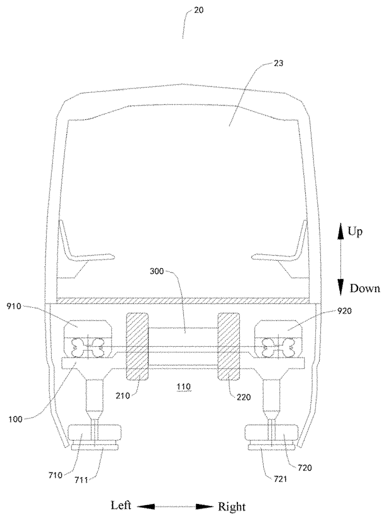
[0071] FIG. 24 is a sectional view of a bogie of a rail vehicle according to an embodiment of the present disclosure;
[0072] FIG. 25 is a sectional view of a bogie of a rail vehicle according to another embodiment of the present disclosure;
[0073] FIG. 26 is a sectional view of a bogie of a rail vehicle according to another embodiment of the present disclosure;
[0074] FIG. 27 is a sectional view of a bogie of a rail vehicle according to another embodiment of the present disclosure;
[0075] FIG. 28 is a sectional view of a bogie of a rail vehicle according to another embodiment of the present disclosure;
[0076] FIG. 29 is a sectional view of a bogie of a rail vehicle according to another embodiment of the present disclosure;
[0077] FIG. 30 is a sectional view of a bogie of a rail vehicle according to another embodiment of the present disclosure;
[0078] FIG. 31 is a sectional view of a bogie of a rail vehicle according to another embodiment of the present disclosure;
[0079] FIG. 32 is a sectional view of a bogie of a rail vehicle according to another embodiment of the present disclosure;
[0080] FIG. 33 is a sectional view of a bogie of a rail vehicle according to another embodiment of the present disclosure;
[0081] FIG. 34 is a sectional view of a bogie of a rail vehicle according to another embodiment of the present disclosure;
[0082] FIG. 35 is a sectional view of a bogie of a rail vehicle according to another embodiment of the present disclosure;
[0083] FIG. 36 is a sectional view of a bogie of a rail vehicle according to another embodiment of the present disclosure;
[0084] FIG. 37 is a sectional view of a bogie of a rail vehicle according to another embodiment of the present disclosure;
[0085] FIG. 38 is a sectional view of a bogie of a rail vehicle according to another embodiment of the present disclosure;
[0086] FIG. 39 is a sectional view of a bogie of a rail vehicle according to another embodiment of the present disclosure;
[0087] FIG. 40 is a sectional view of a bogie of a rail vehicle according to another embodiment of the present disclosure;
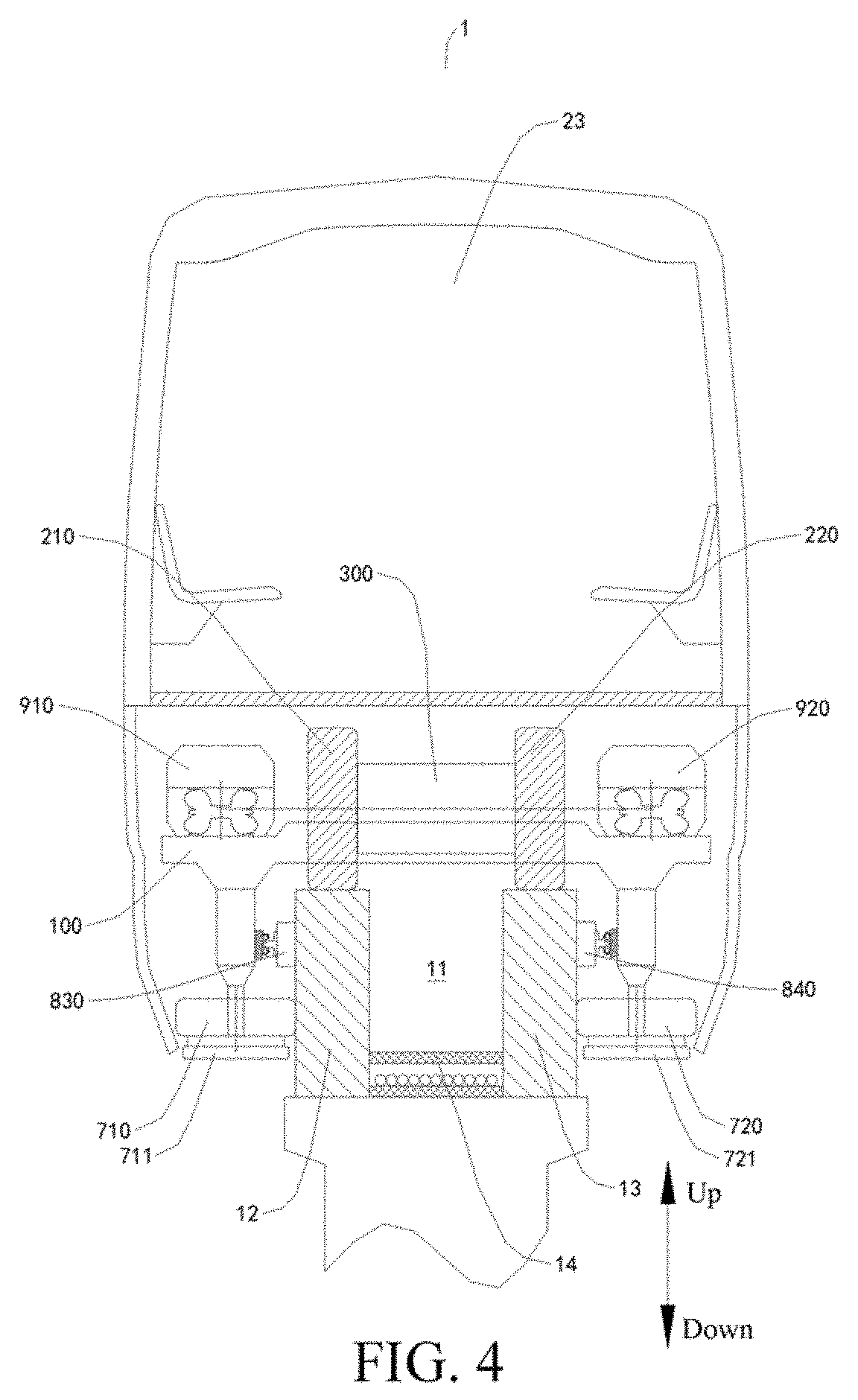
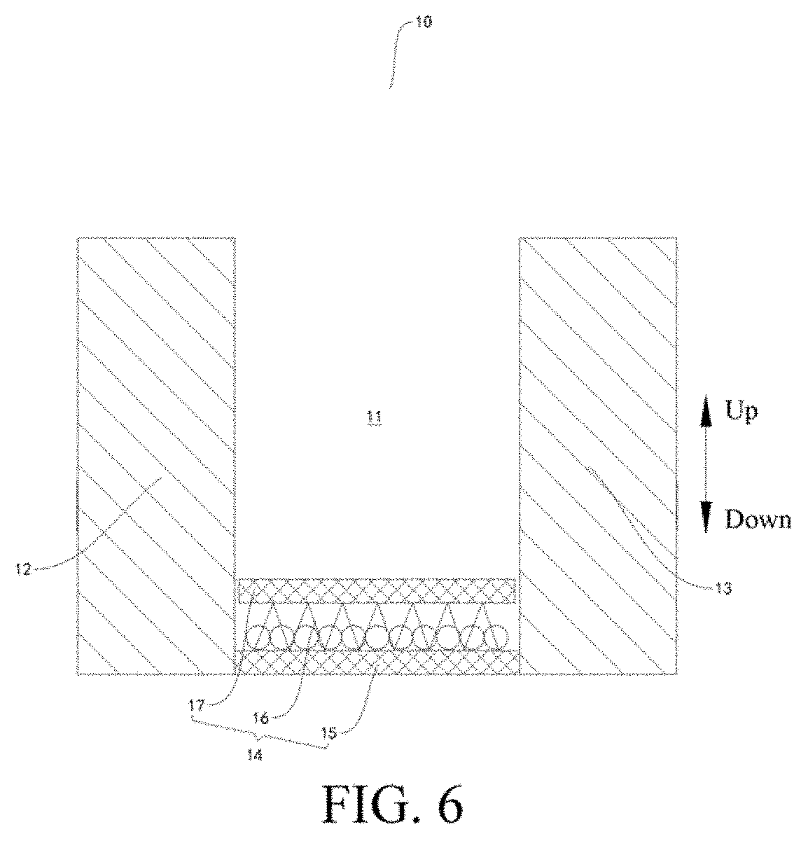
[0088] FIG. 41 is a sectional view of a bogie of a rail vehicle according to another embodiment of the present disclosure;
[0089] FIG. 42 is a schematic of a bogie of a rail vehicle according to another embodiment of the present disclosure;
[0090] FIG. 43 is a schematic of a bogie of a rail vehicle according to another embodiment of the present disclosure;
[0091] FIG. 44 is a schematic of a bogie of a rail vehicle according to another embodiment of the present disclosure;
[0092] FIG. 45 is a sectional view of a rail transport system according to another embodiment of the present disclosure;
[0093] FIG. 46 is a schematic of a bogie of a rail vehicle according to another embodiment of the present disclosure;
[0094] FIG. 47 is a schematic of a bogie of a rail vehicle according to another embodiment of the present disclosure;
[0095] FIG. 48 is a schematic of a bogie of a rail vehicle according to another embodiment of the present disclosure;
[0096] FIG. 49 is a schematic of a bogie of a rail vehicle according to another embodiment of the present disclosure;
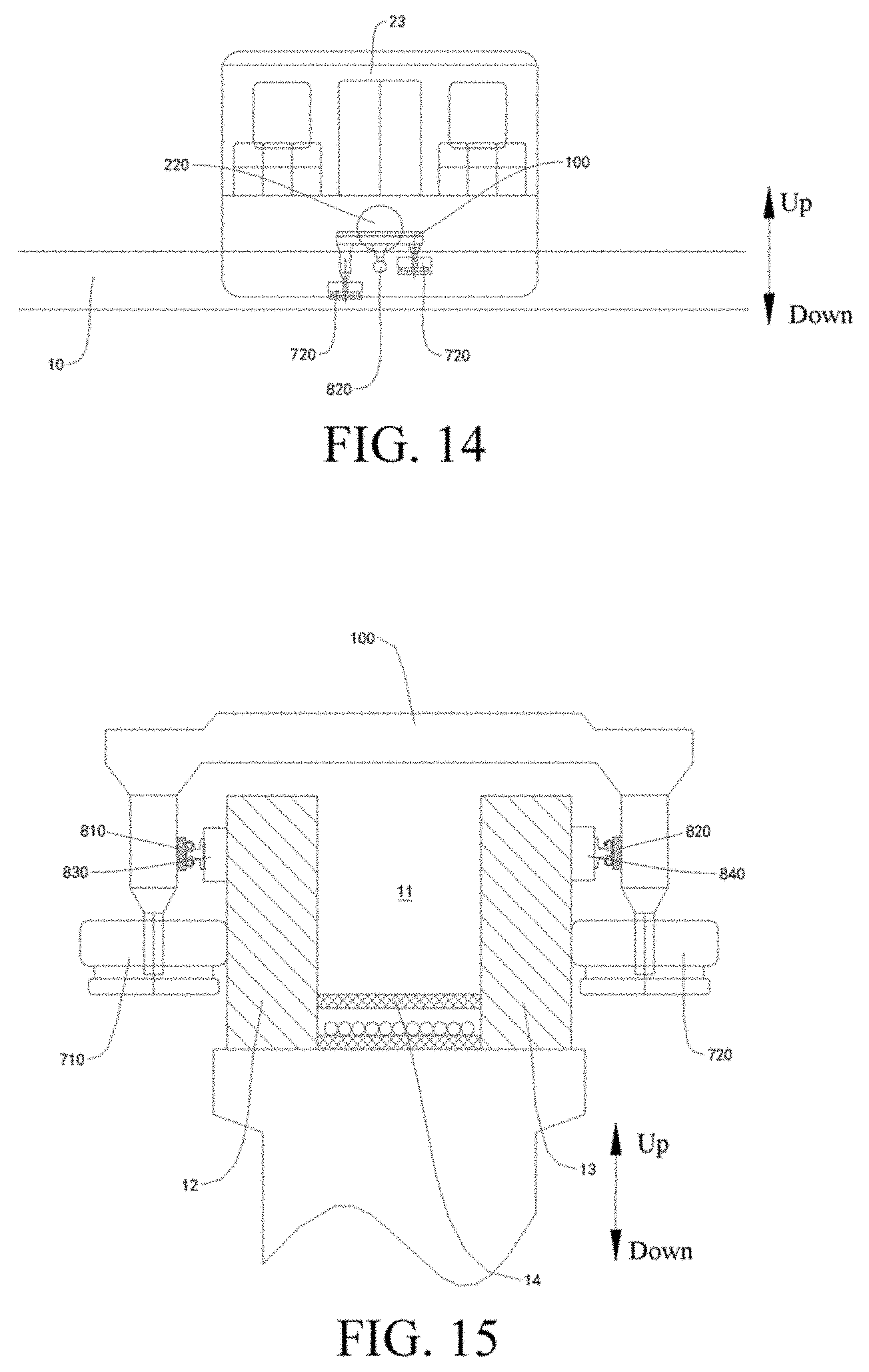
[0097] FIG. 50 is a partial schematic of a rail transport system according to another embodiment of the present disclosure;
[0098] FIG. 51 is a partial schematic of a rail transport system according to another embodiment of the present disclosure;
[0099] FIG. 52 is a partial schematic of a rail transport system according to another embodiment of the present disclosure;
[0100] FIG. 53 is a partial schematic of a rail transport system according to another embodiment of the present disclosure;
[0101] FIG. 54 is a partial schematic of a rail transport system according to another embodiment of the present disclosure;
[0102] FIG. 55 is a partial schematic of a rail transport system according to another embodiment of the present disclosure;
[0103] FIG. 56 is a partial schematic of a rail transport system according to another embodiment of the present disclosure;
[0104] FIG. 57 is a partial schematic of a rail transport system according to another embodiment of the present disclosure;
[0105] FIG. 58 is a schematic of a bogie of a rail vehicle according to another embodiment of the present disclosure;
[0106] FIG. 59 is a schematic of a bogie of a rail vehicle according to another embodiment of the present disclosure;
[0107] FIG. 60 is a schematic of a bogie of a rail vehicle according to another embodiment of the present disclosure;
[0108] FIG. 61 is a schematic of a bogie of a rail vehicle according to another embodiment of the present disclosure;
[0109] FIG. 62 is a schematic of a bogie of a rail vehicle according to another embodiment of the present disclosure;
[0110] FIG. 63 is a schematic of a bogie of a rail vehicle according to another embodiment of the present disclosure;
[0111] FIG. 64 is a schematic of a bogie of a rail vehicle according to another embodiment of the present disclosure;
[0112] FIG. 65 is a schematic of a bogie of a rail vehicle according to another embodiment of the present disclosure;
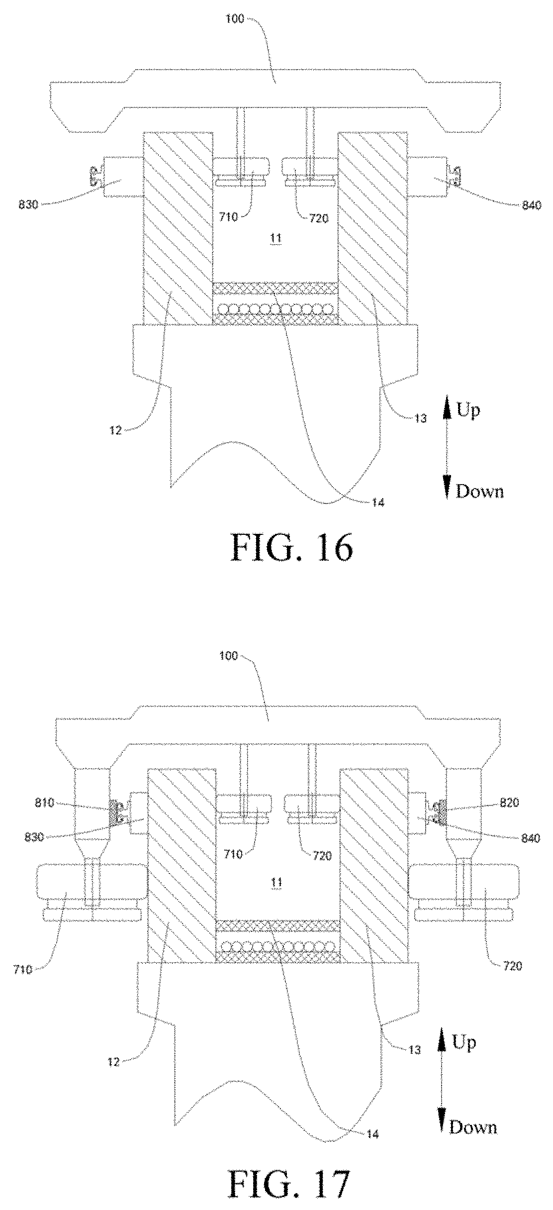
[0113] FIG. 66 is a schematic of a bogie of a rail vehicle according to another embodiment of the present disclosure;
[0114] FIG. 67 is a partial schematic of a rail transport system according to another embodiment of the present disclosure, where an escape door is in a closed state;
[0115] FIG. 68 is a partial schematic of a rail transport system according to another embodiment of the present disclosure, where an escape door is in an open state;
[0116] FIG. 69 is a partial schematic of a rail transport system according to another embodiment of the present disclosure; and
[0117] FIG. 70 is a schematic of a bogie of a rail vehicle according to another embodiment of the present disclosure.
REFERENCE NUMERALS OF THE ACCOMPANYING DRAWING
[0118] rail transport system 1, [0119] rail 10, escape passage 11, first rail beam 12, second rail beam 13, weight bearing floor 14, connection beam 15, support frame 16, support plate 17, anti-detaching edge 18, [0120] rail vehicle 20, bogie 21, vehicle body 22, compartment 23, escape door 24, escape port 25, escape cover plate 26, escape ladder 27, power battery 28, first end 31 of the escape door 24, second end 32 of the escape door 24, [0121] bogie frame 100, second recess 110, [0122] first running wheel 210, second running wheel 220, third running wheel 230, fourth running wheel 240, first connection shaft 250, second connection shaft 260, [0123] driving device 300, first driving device 310, second driving device 320, [0124] first horizontal wheel 710, second horizontal wheel 720, first horizontal safety wheel 711, second horizontal safety wheel 721, [0125] first collector shoe 810, second collector shoe 820, first conductive rail 830, second conductive rail 840, [0126] first support suspension device 910, second support suspension device 920, third support suspension device 930, and fourth support suspension device 940.
DETAILED DESCRIPTION
[0127] The following describes embodiments of the present disclosure in detail. Examples of the embodiments are shown in the accompanying drawings. The same or similar elements or the elements having same or similar functions are denoted by same or similar reference numerals throughout the descriptions. The embodiments described below with reference to the accompanying drawings are exemplary, aim to explain the disclosure, but cannot be understood as a limitation on the disclosure.
[0128] The present disclosure proposes a rail transport system 1 has advantages such as facilitation of evacuation of passengers in an emergency, low costs, small occupied space, small rail weight bearing, and high stability.
[0129] The rail transport system 1 according to an embodiment of the present disclosure is described below with reference to accompanying drawings.
[0130] As shown in FIG. 1 to FIG. 70, the rail transport system 1 according to this embodiment of the present disclosure includes a rail 10 and a rail vehicle 20.
[0131] A first recess as an escape passage 11 is constructed on the rail 10. The rail vehicle 20 includes a bogie 21 and a vehicle body 22, and the bogie 21 has a second recess 110 suitable for straddling the rail. The second recess 110 is a straddle recess. In a left and right direction, a minimum distance between two ends of the second recess 110 is greater than or equal to a minimum width of the rail. The bogie 21 is movable and straddles on the rail 10, and the vehicle body 22 is connected to the bogie 21 and pulled by the bogie 21 to travel along the rail 10. In an embodiment, in a left and right direction, a minimum distance between two ends of the second recess 110 is greater than or equal to a minimum width of the rail.
[0132] Herein, a person skilled in the art needs to understand that, the rail 10 is provided with the escape passage 11 means that, the escape passage 11 is disposed on the rail 10 itself other than disposed on another additional component on the rail 10. To be specific, compared with the structure of the escape passage in the related art, in the rail transport system 1 according to this embodiment of the present disclosure, the rail 10 does not need to be provided with other components such as a frame and a floor, and the escape passage 11 is formed on the rail 10 itself.
[0133] In the rail transport system 1 according to this embodiment of the present disclosure, the escape passage 11 is disposed on the rail 10. When an emergency occurs, passengers can be evacuated in time by using the escape passage 11. Moreover, because the escape passage 11 is disposed on the rail 10 itself, no other additional structure needs to be added to the rail 10, and only the escape passage 11 needs to be disposed on the rail 10 along the length direction of the rail 10. Therefore, the amount of work of the rail transport system 1 may be greatly reduced. On one hand, costs are reduced, and on the other hand, occupied space is reduced. Moreover, the weight borne by the rail 10 does not need to be increased, which is favorable to stability of the rail 10. Therefore, the rail transport system 1 according to this embodiment of the present disclosure has advantages such as facilitation of evacuation of passengers in an emergency, low costs, small occupied space, small rail weight bearing, and high stability.
[0134] The rail transport system 1 according to a specific embodiment of the present disclosure is described below with reference to accompanying drawings.
[0135] As shown in FIG. 1 to FIG. 70, the rail transport system 1 according to this embodiment of the present disclosure includes a rail 10 and a rail vehicle 20. The vehicle body 22 includes a plurality of compartments 23 hinged sequentially along a length direction of the rail 10. In the length direction of the rail 10, a surface that is of a compartment 23 at the at least one end of the vehicle body 22 and faces away from an adjacent compartment 23 is provided with an escape door 24 that can be opened and closed.
[0136] In some embodiments of the present disclosure, as shown in FIG. 1 to FIG. 5, a vehicle body 22 includes a plurality of compartments 23 hinged sequentially along a length direction of a rail 10. In the length direction of the rail 10, a surface that is of a compartment 23 at the at least one end of the vehicle body 22 and faces away from an adjacent compartment 23 is provided with an escape door 24 that can be opened and closed. That is, each end of the vehicle body 22 has a compartment 23, the compartment 23 of at least one end of the vehicle body 22 has an escape door 24 on the compartment's surface facing away from an adjacent compartment 23, and the escape door 24 can be opened and closed. In other words, the escape door 24 is disposed on an end surface of at least one of two compartments 23 located at two ends of the vehicle body 22. To be specific, the escape door 24 is disposed on the compartment 23 at the at least one end of the vehicle body 22 in the length direction of the rail 10. In an embodiment, the escape door 24 is disposed on a first end surface of the compartment 23 at the at least one end, and the first end surface is a surface away from the adjacent compartment. The escape door 24 has a first end 31 and a second end 32, and the first end 31 of the escape door 24 is pivotably mounted onto the corresponding compartment 23. When opened, the escape door 24 leans to a horizontal plane, and the second end 32 of the escape door 24 tilts downward and stretches into the rail 10, that is, stretches into an escape passage 11. In this way, when an emergency occurs, a rail vehicle 20 is actively or passively stopped, the escape door 24 is opened, and a lower end stretches into the escape passage 11. Passengers in the compartment 23 can slide downward to the escape passage 11 through the escape door 24, and then be evacuated from the escape passage 11.
[0137] In an embodiment, the first end 31 of the escape door 24 is disposed adjacent to the vehicle bottom, and the second end 32 of the escape door 24 is disposed adjacent to the vehicle top when the escape door 24 is closed. In other words, when the escape door 24 is closed, the second end 32 of the escape door 24 is located above the first end 31 of the escape door 24; and when the escape door 24 is opened, the second end 32 of the escape door 24 is located below the first end 31 of the escape door 24. Therefore, the escape door 24 is converted from a closed state to an open state through downward flipping. A flipping-type structure is used for the escape door 24, and a passenger in the vehicle can quickly open the escape door 24 in need of only a simple operation, to effectively improve escape efficiency.
[0138] Preferably, an inner surface of the escape door 24 is provided with a slide rail to help a passenger slide on the slide rail to the escape passage 11. It may be understood herein that, the inner surface of the escape door 24 is a surface facing the inside of the vehicle when the escape door 24 is closed.
[0139] In some other specific embodiments of the present disclosure, as shown in FIG. 67 and FIG. 68, a vehicle body 22 includes a plurality of compartments 23 hinged sequentially along a length direction of a rail 10. In the length direction of the rail 10, a surface that is of a compartment 23 at the at least one end of the vehicle body 22 and faces away from an adjacent compartment 23 is provided with an escape door 24 that can be opened and closed. Moreover, an escape port 25 and an escape cover plate 26 are disposed on an inner floor of the compartment 23 at the at least one end of the vehicle body 22, that is, the escape port 25 and the escape cover plate 26 are disposed on the inner floor of the compartment 23 provided with the escape door 24. The escape cover plate 26 collaborates with the escape door 24 and is used to open and close the escape port 25. When a rail vehicle 20 runs normally, the escape door 24 is closed and the escape cover plate 26 closes the escape port 25 (as shown in FIG. 67). When an emergency occurs, the rail vehicle 20 is actively or passively stopped, the escape door 24 is opened and the escape cover plate 26 opens the escape port 25 (as shown in FIG. 68). The passengers in the compartment 23 can enter the escape passage 11 through the escape port 25, and then be evacuated from the escape passage 11. Moreover, even if the rail vehicle 20 is forced to stop at a turn of the rail 10, because the escape door 24, when opened, does not need to fit in with the rail 10, the escape door 24 does not collide with the rail 10, to facilitate evacuation of the passengers at the bend of the rail 10.
[0140] Preferably, in the length direction of the rail 10, each of two end surfaces of two compartments 23 located at two ends of the vehicle body 22 is provided with an escape door 24, the end surface is a first surface of the compartment 23, and the first surface is a surface of the current compartment away from an adjacent compartment. In an emergency, the escape doors 24 are simultaneously opened at the two ends of the vehicle body 22, and a wide air convection passage can be formed, so that toxic gases such as smog in the vehicle body 22 can be quickly dissipated. Moreover, a flipping-type structure is used for the escape door 24, and the passenger in the vehicle can quickly open the escape door 24 in need of only a simple operation, to effectively improve escape efficiency.
[0141] In an embodiment, The escape door 24 has a first end 31 and a second end 32, and the second end 32 of the escape door 24 is pivotably mounted onto the corresponding compartment 23. The second end 32 of the escape door 24 is disposed adjacent to the vehicle top, and the first end 31 of the escape door 24 is disposed adjacent to the vehicle bottom when the escape door 24 is closed. In other words, when the escape door 24 is closed, the first end 31 of the escape door 24 is located below the second end 32 of the escape door 24; and when the escape door 24 is opened, the first end 31 of the escape door 24 may be located below the second end 32 of the escape door 24, or may be located above the second end 32 of the escape door 24. Therefore, the escape door 24 is converted from a closed state to an open state through upward flipping. A flipping-type structure is used for the escape door 24, and the passenger in the vehicle can quickly open the escape door 24 in need of only a simple operation, to effectively improve escape efficiency, and facilitate collaboration between the escape door 24 and the escape cover plate 26.
[0142] Optionally, collaboration between the escape cover plate 26 and the escape door 24, may be dominated by the escape door 24, or may be dominated by the escape cover plate 26. Specifically, when passengers need to be evacuated, the escape door 24 may be actively opened, and the escape door 24 drives the escape cover plate 26 to open the escape port 25; or the escape cover plate 26 may be actively opened, and the escape cover plate 26 drives the escape door 24 to be opened. Preferably, the foregoing collaboration is dominated by the escape cover plate 26, that is, the escape cover plate 26 opens to drive the escape door 24 to be opened. In this way, when the escape cover plate 26 is opened, an article or a passenger above the escape cover plate 26 can be prevented from falling.
[0143] Further, as shown in FIG. 67 and FIG. 68, an escape ladder 27 leading to the rail 10 is disposed in the escape port 25. To be specific, the escape ladder 27 leading to the escape passage 11 is disposed in the escape port 25. After the escape port 25 is opened, a passenger in the vehicle may be transferred to the escape passage 11 through the escape ladder 27.
[0144] Optionally, the escape ladder 27 may be in a fixed state and is always suspending in the escape port 25, and a lower end of the escape ladder 27 and an inner bottom surface of the escape passage 11 are spaced apart, to avoid affecting travelling of the rail vehicle 20.
[0145] The escape ladder 27 may also have two states, a retraction state and a stretching state, and the vehicle body further includes a stretching/retraction driving device used to drive stretching/retraction of the escape ladder 27. After the escape port 25 is opened, the escape ladder 27 may be manually controlled to stretch into the escape passage 11, or the escape ladder 27 may automatically stretch into the escape passage 11 through collaboration. In this embodiment, after stretching, the escape ladder 27 may be directly placed on the inner bottom surface of the escape passage 11, or the escape ladder 27 and the inner bottom surface of the escape passage 11 may be spaced apart.
[0146] Preferably, the escape cover plate 26 may be pivotably mounted onto the escape door 24. After the escape door 24 is flipped upward and is opened, the escape cover plate 26 rotates collaboratively to be laminated onto the inner surface of the escape door 24, thereby saving space, and preventing the escape cover plate 26 from affecting evacuation of passengers.
[0147] In some specific examples of the present disclosure, as shown in FIG. 6, a rail 10 includes a first rail beam 12, a second rail beam 13, and a weight bearing floor 14.
[0148] The first rail beam 12 and the second rail beam 13 are disposed in parallel and at an interval, and a bogie 21 straddles the first rail beam 12 and the second rail beam 13. The weight bearing floor 14 is disposed between the first rail beam 12 and the second rail beam 13, the weight bearing floor 14 is connected to the first rail beam 12 and the second rail beam 13 respectively, and an escape passage 11 is defined among the first rail beam 12, the second rail beam 13, and the weight bearing floor 14. Therefore, the rail 10 may be provided with the escape passage 11 by using the structure of the rail 10, and no additional component needs to be disposed. Therefore, costs are low, occupied space is small, and it is favorable to reduction in the weight borne by the rail 10. Moreover, the dimension of the rail beam is relatively small, the occupied space area is small, the weight is relatively light, the energy efficiency is high, and it is economical.
[0149] As shown in FIG. 6, the weight bearing floor 14 includes a connection beam 15, a support frame 16, and a support plate 17. The connection beam 15 extends along an interval direction of the first rail beam 12 and the second rail beam 13, and two ends of the connection beam 15 are respectively connected to a lower portion of the first rail beam 12 and a lower portion of the second rail beam 13. The support frame 16 is mounted onto the connection beam 15. The support plate 17 is connected to the support frame 16 and supported by the support frame 16, and the support plate 17 forms a bottom surface of the escape passage 11. The rail 10 usually needs to be built overhead by using piers, and there is a predetermined distance between the piers. Therefore, by using the structure of the foregoing weight bearing floor 14, the escape passage 11 extending along the length direction of the rail 10 may be formed between the piers, material consumption is small, and costs are low.
[0150] Preferably, as shown in FIG. 6, the support plate 17 and at least one of the first rail beam 12 and the second rail beam 13 are spaced apart in a horizontal direction. In other words, the support plate 17 and the first rail beam 12 are spaced apart in the horizontal direction, or the support plate 17 and the second rail beam 13 are spaced apart in the horizontal direction, or the support plate 17 and each of the first rail beam 12 and the second rail beam 13 are spaced apart in the horizontal direction. In this way, it may be convenient to insert a tool into a gap between the support frame 16 and a rail beam, thereby levering the support plate 17 to facilitate repair.
[0151] Optionally, there is a plurality of connection beams 15 that is spaced apart along the length direction of the rail 10, and there is a plurality of support plates 17 that is sequentially connected along the length direction of the rail 10. On one hand, a single connection beam 15 and a single support plate 17 facilitate processing, and on the other hand, facilitate entire construction of the rail 10.
[0152] A person skilled in the art needs to understand that, sequential connection of the plurality of support plates 17 includes direct connection or indirect connection, and prefers the direct connection. When the plurality of support plates 17 is indirectly connected, a gap between neighboring support plates 17 needs to ensure that passengers can smoothly cross over, that is, does not affect evacuation of the passengers.
[0153] Further, the rail 10 also includes an anti-detaching edge 18. Specifically, the anti-detaching edge 18 is disposed at the at least one of an upper end and a lower end of at least one of the first rail beam 12 and the second rail beam 13, and the anti-detaching edge 18 extends outward along the horizontal direction and is used to prevent the bogie 21 from being disengaged from the rail 10. Specifically, the anti-detaching edge 18 may be disposed on the top and/or the bottom of the first rail beam 12, and may be disposed on an outer side surface and/or an inner side surface of the first rail beam 12; or the anti-detaching edge 18 may be disposed on the top and/or the bottom of the second rail beam 13, and may be disposed on an outer side surface and/or an inner side surface of the second rail beam 13. Herein, a person skilled in the art needs to understand that, the anti-detaching edge 18 is disposed to prevent the bogie 21 from being derailed from the rail 10, thereby ensuring stability of the rail vehicle 20 in a travelling situation such as turning. Therefore, a partial structure of the bogie 21 needs to be placed right below the top anti-detaching edge 18 and/or right above the bottom anti-detaching edge 18.
[0154] For example, as shown in FIG. 8, the first rail beam 12 and the second rail beam 13 are formed by bonding reinforcing steel bars and concrete. Each of the inner side surface and the outer side surface of the top of the first rail beam 12 is provided with an anti-detaching edge 18, and each of the inner side surface and the outer side surface of the top of the second rail beam 13 is provided with an anti-detaching edge 18. A first horizontal wheel 710 of the bogie 21 fits in on the outer side surface of the first rail beam 12 and is located below the anti-detaching edge 18 on the outer side surface of the top of the first rail beam 12, and a second horizontal wheel 720 of the bogie 21 fits in on the outer side surface of the second rail beam 13 and is located below the anti-detaching edge 18 on the outer side surface of the top of the second rail beam 13. In this way, the anti-detaching edges 18 may stop the horizontal wheels from moving upward, thereby prevents detachment.
[0155] As shown in FIG. 9, the first rail beam 12 and the second rail beam 13 are formed by splicing steel plates. Each of the inner side surface and the outer side surface of the top of the first rail beam 12 is provided with an anti-detaching edge 18, each of the inner side surface and the outer side surface of the bottom of the first rail beam 12 is provided with an anti-detaching edge 18, each of the inner side surface and the outer side surface of the top of the second rail beam 13 is provided with an anti-detaching edge 18, and each of the inner side surface and the outer side surface of the bottom of the second rail beam 13 is provided with an anti-detaching edge 18. A first horizontal wheel 710 of the bogie 21 fits in on the outer side surface of the first rail beam 12 and is located between the anti-detaching edge 18 on the outer side surface of the top of the first rail beam 12 and the anti-detaching edge 18 on the outer side surface of the bottom, and a second horizontal wheel 720 of the bogie 21 fits in on the outer side surface of the second rail beam 13 and is located between the anti-detaching edge 18 on the outer side surface of the top of the second rail beam 13 and the anti-detaching edge 18 on the outer side surface of the bottom. In this way, the anti-detaching edges 18 may stop the horizontal wheels from moving upward and downward to prevent the first horizontal wheel 710 from being separated from the first rail beam 12 and prevent the second horizontal wheel 720 from being separated from the second rail beam 13, thereby playing a role in preventing detachment.
[0156] In some specific embodiments of the present disclosure, as shown in FIG. 10, the bogie 21 includes a bogie frame 100, a first running wheel 210, a second running wheel 220, and a driving device 300.
[0157] The bogie frame 100 has a second recess 110 suitable for straddling the rail 10, that is, the second recess is disposed in the bogie frame. The second recess 110 is a straddle recess. Specifically, the second recess 110 is formed by a hollow portion jointly defined by the bottom of the bogie frame 100, a first horizontal wheel 710, and a second horizontal wheel 720, and the innermost sides of the first horizontal wheel 710 and the second horizontal wheel 720 is in contact with the outer side of the rail 10. The first running wheel 210 and the second running wheel 220 are pivotably mounted onto the bogie frame 100 respectively and are coaxially spaced apart. The first running wheel 210 fits in on an upper surface of the first rail beam 12, and the second running wheel 220 fits in on an upper surface of the second rail beam 13. The driving device 300 is mounted onto the bogie frame 100, and the driving device 300 is located between the first running wheel 210 and the second running wheel 220. The first running wheel 210 and the second running wheel 220 are driven by the driving device 300. Driven by the driving device 300, the first running wheel 210 and the second running wheel 220 drives the bogie 21 to run along the rail 10, thereby pulling the vehicle body 22 to travel. Therefore, the driving device 300 may be mounted in the gap between the first running wheel 210 and the second running wheel 220, so as to save space, improve space utilization, and facilitate distribution of the center of gravity of the vehicle body 22. Moreover, a center distance of a tyre may be increased, to improve uniform stability of driving of the driving device 300 for the first running wheel 210 and the second running wheel 220, thereby improving stability and comfort of the rail transport system 1.
[0158] In some other specific embodiments of the present disclosure, as shown in FIG. 46 to FIG. 49, the bogie 21 includes a bogie frame 100, a first running wheel 210, a second running wheel 220, a third running wheel 230, a fourth running wheel 240, and a driving device.
[0159] The bogie frame 100 has a second recess 110 suitable for straddling the rail 10, that is, the second recess 110 is disposed in the bogie frame 100. The first running wheel 210 and the second running wheel 220 are pivotably mounted onto the bogie frame 100 respectively and are coaxially spaced apart. The first running wheel 210 fits in on an upper surface of the first rail beam 12, and the second running wheel 220 fits in on an upper surface of the second rail beam 13. The third running wheel 230 and the fourth running wheel 240 are pivotably mounted onto the bogie frame 100 respectively and are coaxially spaced apart. The third running wheel 230 fits in on the upper surface of the first rail beam 12. The third running wheel 230 and the first running wheel 210 are spaced apart in the length direction of the rail 10. To be specific, the third running wheel 230 and the first running wheel 210 are spaced apart in the length direction of the first rail beam 12. The fourth running wheel 240 fits in on the upper surface of the second rail beam 13. The fourth running wheel 240 and the second running wheel 220 are spaced apart in the length direction of the rail 10. To be specific, the fourth running wheel 240 and the second running wheel 220 are spaced apart in the length direction of the second rail beam 13. The driving device is mounted onto the bogie frame 100, the driving device is located between the first running wheel 210 and the second running wheel 220 and/or the driving device is located between the third running wheel 230 and the fourth running wheel 240, and the first running wheel 210 and the second running wheel 220 are driven by the driving device, and/or the third running wheel 230 and the fourth running wheel 240 are driven by the driving device. In this way, a requirement of bearing a relatively large weight can be satisfied, and the four running wheels can bear a larger weight, which is favorable improvement in quantity of passengers in the rail vehicle 20 and the dimension of the vehicle body. Moreover, space use efficiency of the bogie 21 can be effectively improved, thereby reducing the occupied space area of the entire vehicle.
[0160] For example, as shown in FIG. 46, there may be one driving device defined as a first driving device 310, the first driving device 310 is disposed between the first running wheel 210 and the second running wheel 220, and the first running wheel 210 and the second running wheel 220 are driven by the first driving device 310.
[0161] As shown in FIG. 47, there may be one driving device defined as a second driving device 320, the second driving device 320 is disposed between the third running wheel 230 and the fourth running wheel 240, and the third running wheel 230 and the fourth running wheel 240 are driven by the second driving device 320.
[0162] As shown in FIG. 48, there may be two driving devices defined as a first driving device 310 and a second driving device 320 respectively. The first driving device 310 is disposed between the first running wheel 210 and the second running wheel 220, and the first running wheel 210 and the second running wheel 220 are driven by the first driving device 310. The second driving device 320 is disposed between the third running wheel 230 and the fourth running wheel 240, and the third running wheel 230 and the fourth running wheel 240 are driven by the second driving device 320. The first driving device 310 is closer to the first running wheel 210 than the second running wheel 220, and/or the second driving device 320 is closer to the fourth running wheel 240 than the third running wheel 230. Preferably, the first driving device 310 is closer to the first running wheel 210 than the second running wheel 220, and the second driving device 320 is closer to the fourth running wheel 240 than the third running wheel 230. To be specific, the first driving device 310 and the second driving device 320 are diagonally disposed. Therefore, the bogie 21 is balanced in a width direction of the rail 10, and a differential may be saved, thereby reducing costs.
[0163] Optionally, the first running wheel 210 and the second running wheel 220 are connected by using a first connection shaft 250, and/or the third running wheel 230 and the fourth running wheel 240 are connected by using a second connection shaft 260. The driving device is in transmission connection to the first connection shaft 250 and/or the second connection shaft 260.
[0164] For example, as shown in FIG. 49, the first running wheel 210 and the second running wheel 220 are connected by using a first connection shaft 250, the third running wheel 230 and the fourth running wheel 240 are connected without a connection shaft as follower wheels. There is one driving device defined as a first driving device 310, and the first driving device 310 is in transmission connection to the first connection shaft 250.
[0165] In other words, FIG. 10 shows the bogie 21 having two running wheels, FIG. 46 to FIG. 49 show the bogie 21 having four running wheels, and the bogie 21 having four running wheels may have a single connection shaft, or may have two connection shafts. The structure of two connection shafts may be used, and stability performance and safety performance of the system can be greatly improved.
[0166] In some specific embodiments of the present disclosure, the bogie 21 further includes a first horizontal wheel 710 and a second horizontal wheel 720, where there may be one or more first horizontal wheels 710 and one or more second horizontal wheels 720 respectively.
[0167] The first horizontal wheel 710 is pivotably mounted onto the bogie frame 100 and is suitable for fitting in on the first side surface of the rail 10, The second horizontal wheel 720 is pivotably mounted onto the bogie frame 100 and is suitable for fitting in on the second side surface of the rail 10. In an embodiment, the first horizontal wheel 710 is pivotably mounted onto the bogie frame 100 and fits in on a side surface of the first rail beam 12. The second horizontal wheel 720 is pivotably mounted onto the bogie frame 100 and fits in on a side surface of the second rail beam 13. On one hand, when the rail 10 is steered, the first horizontal wheel 710 and the second horizontal wheel 720 fit in on a side surface of the rail 10, thereby being passively steered along the rail 10, and then drives the rail vehicle 20 to be steered. On the other hand, stability of the rail vehicle 20 during travelling may be improved.
[0168] Further, the bogie 21 also includes a first horizontal safety wheel 711 connected to the first horizontal wheel 710 and moving in synchronization with the first horizontal wheel 710, and a second horizontal safety wheel 721 connected to the second horizontal wheel 720 and moving in synchronization with the second horizontal wheel 720. The outer diameter of the first horizontal safety wheel 711 is less than the outer diameter of the first horizontal wheel 710, and the outer diameter of the second horizontal safety wheel 721 is less than the outer diameter of the second horizontal wheel 720. As shown in FIG. 4, FIG. 5, and FIG. 7, the bottom of the first horizontal wheel 710 is connected to a first horizontal safety wheel 711 moving in synchronization with the first horizontal wheel 710, and the outer diameter of the first horizontal safety wheel 711 is less than the outer diameter of the first horizontal wheel 710. The bottom of the second horizontal wheel 720 is connected to a second horizontal safety wheel 721 moving in synchronization with the second horizontal wheel 720, and the outer diameter of the second horizontal safety wheel 721 is less than the outer diameter of the second horizontal wheel 720. Normally, the first horizontal safety wheel 711 and the second horizontal safety wheel 721 are not in contact with a rail beam. When a tyre of a horizontal wheel is flat, a horizontal safety wheel in place of the horizontal wheel is in contact with the rail beam, to ensure stability of the rail vehicle 20 during travelling. For example, when the first horizontal wheel 710 is normal, the first horizontal safety wheel 711 is not in contact with the first rail beam 12. When a tyre of the first horizontal wheel 710 is flat, the first horizontal safety wheel 711 is in contact with a side surface of the first rail beam 12, thereby replacing the first horizontal wheel 710.
[0169] In some specific examples of the present disclosure, as shown in FIG. 11 and FIG. 50, there is a plurality of first horizontal wheels 710 located at a same height in an up and down direction and there is a plurality of second horizontal wheels 720 located at a same height in the up and down direction. FIG. 11 shows an example in which a second horizontal wheel 720 and another second horizontal wheel 720 of a bogie 21 having two running wheels are located at a same height. FIG. 50 shows an example in which a second horizontal wheel 710 and another second horizontal wheel 720 of a bogie 21 having four running wheels are located at a same height. Therefore, balance of entire steering performance of the rail vehicle 20 may be facilitated, and a force applied during forward movement or backward movement is uniform, thereby facilitating improvement in turning performance of the rail vehicle 20.
[0170] In some specific examples of the present disclosure, as shown in FIG. 12 and FIG. 51, there is a plurality of first horizontal wheels 710 spaced apart and coaxially disposed along an up and down direction, and there is a plurality of second horizontal wheels 720 spaced apart and coaxially disposed along the up and down direction. FIG. 12 shows an example in which a plurality of first horizontal wheels 710 of a bogie 21 having two running wheels is coaxially disposed vertically, and a plurality of second horizontal wheels 720 is coaxially disposed vertically. FIG. 51 shows an example in which a plurality of first horizontal wheels 710 of a bogie 21 having four running wheels is coaxially disposed vertically, and a plurality of second horizontal wheels 720 is coaxially disposed vertically. In this way, stability performance of the entire vehicle can be improved, and the horizontal wheel on the bottom plays a role of stabilization, thereby reducing an overturn risk of the rail vehicle 20 during turning or high-speed travelling.
[0171] In some specific examples of the present disclosure, as shown in FIG. 13, FIG. 14, FIG. 52, and FIG. 53, there is a plurality of first horizontal wheels 710 spaced apart along an up and down direction and the length direction of the rail 10 respectively, and there is a plurality of second horizontal wheels 720 spaced apart along an up and down direction and the length direction of the rail 10 respectively. Specifically, there is a plurality of first horizontal wheels 710 spaced apart along the up and down direction and the length direction of the first rail beam 12 respectively, and there is a plurality of second horizontal wheels 720 spaced apart along the up and down direction and the length direction of the second rail beam 13 respectively. To be specific, the first horizontal wheels 710 are staggered vertically, and the second horizontal wheels 720 are staggered vertically. To be specific, an n.sup.th first horizontal wheel 710 may be located above or below an (n+1).sup.th first horizontal wheel 720, and an (n+2).sup.th first horizontal wheel 720 may be located above or below the (n+1).sup.th first horizontal wheel 720. Specifically, the n.sup.th first horizontal wheel 710 and the (n+2).sup.t first horizontal wheel 720 are located at a same height, where n is an integer greater than or equal to 1. The first horizontal wheel 710 may be located above the second horizontal wheel 720, or may be located below the second horizontal wheel 720. FIG. 13 and FIG. 14 show an example in which first horizontal wheels 710 of a bogie 21 having two running wheels are staggered vertically, and second horizontal wheels 720 are staggered vertically. FIG. 52 and FIG. 53 show an example in which first horizontal wheels 710 of a bogie 21 having four running wheels are staggered vertically, and second horizontal wheels 720 are staggered vertically. In this way, the horizontal wheel on the top can play a role of guiding during corresponding travelling, and the horizontal wheel on the bottom is relatively far away from the vehicle body 22, and can play a role of stabilization and overturn prevention.
[0172] In some specific embodiments of the present disclosure, as shown in FIG. 15, the first horizontal wheel 710 is suitable for fitting in on one outer side surface of the rail 10 and the second horizontal wheel 720 is suitable for fitting in on another outer side surface of the rail 10. Specifically, the first horizontal wheel 710 fits in on the outer side surface of the first rail beam 12, and the second horizontal wheel 720 fits in on the outer side surface of the second rail beam 13, that is, both of the horizontal wheels fit in on the outer side surface of the rail 10. Therefore, a center distance between the two horizontal wheels is designed as a possible maximum distance, which can improve stability performance of the system, and also facilitate gravity center distribution of the bogie 21 and the entire vehicle.
[0173] In some specific embodiments of the present disclosure, as shown in FIG. 16, the first horizontal wheel 710 is suitable for fitting in on one inner side surface of the rail 10 and the second horizontal wheel 720 is suitable for fitting in on another inner side surface of the rail 10. Specifically, the first horizontal wheel 710 fits in on the inner side surface of the first rail beam 12, and the second horizontal wheel 720 fits in on the inner side surface of the second rail beam 13, that is, both of the horizontal wheels fit in on the inner side surface of the rail 10. In this way, space inside the rail 10 can be effectively used, to improve space utilization of the entire vehicle, and a horizontal wheel and a conductive rail are respectively located on both sides of a rail beam, which can effectively reduce space on the bottom of the vehicle body 22 and reduce the height of the entire vehicle.
[0174] In some other specific embodiments of the present disclosure, as shown in FIG. 17 to FIG. 19, there is a plurality of first horizontal wheels 710 respectively fitting in on one outer side surface and one inner side surface of the rail 10, and there is a plurality of second horizontal wheels 720 respectively fitting in on another outer side surface and another inner side surface of the rail 10. Specifically, there is a plurality of first horizontal wheels 710 respectively fitting in on the outer side surface and the inner side surface of the first rail beam 12, and there is a plurality of second horizontal wheels 720 respectively fitting in on the outer side surface and the inner side surface of the second rail beam 13. To be specific, horizontal wheels are fitting in on both the outer side surface and the inner side surface of the rail 10. The horizontal wheels are simultaneously arranged on the inner side and the outer side, to play a role of stabilization and overturn prevention, and stability performance and safety performance of the rail vehicle 20 can be greatly improved.
[0175] Optionally, as shown in FIG. 17, the first horizontal wheel 710 fitting in on the inner side surface of the first rail beam 12 and the second horizontal wheel 720 fitting in on the inner side surface of the second rail beam 13 are located at a same height in the up and down direction. As shown in FIG. 18 and FIG. 19, the first horizontal wheel 710 fitting in on the inner side surface of the first rail beam 12 and the second horizontal wheel 720 fitting in on the inner side surface of the second rail beam 13 are located at different heights in the up and down direction. For example, as shown in FIG. 18, the first horizontal wheel 710 fitting in on the inner side surface of the first rail beam 12 is higher than the second horizontal wheel 720 fitting in on the inner side surface of the second rail beam 13. For another example, as shown in FIG. 19, the first horizontal wheel 710 fitting in on the inner side surface of the first rail beam 12 is lower than the second horizontal wheel 720 fitting in on the inner side surface of the second rail beam 13, and the first horizontal wheel 710 and the second horizontal wheel 720 are located at different heights in the up and down direction.
[0176] During specific implementation, the first horizontal wheel 710 fitting in on the inner side surface of the first rail beam 12 and the second horizontal wheel 720 fitting in on the inner side surface of the second rail beam 13 may be located at a same height or located at different heights, and the first horizontal wheel 710 fitting in on the outer side surface of the first rail beam 12 and the second horizontal wheel 720 fitting in on the outer side surface of the second rail beam 13 may also be located at a same height or located at different heights.
[0177] In some examples of the present disclosure, as shown in FIG. 11 to FIG. 41 and FIG. 50 to FIG. 57, the bogie 21 further includes a first collector shoe 810 and a second collector shoe 820.
[0178] The first collector shoe 810 is disposed on the bogie frame 100 and is suitable for fitting in with the first conductive rail on the first side of the rail 10, and the second collector shoe 820 is disposed on the bogie frame 100 and is suitable for fitting in with the second conductive rail on the second side of the rail 10. Specifically, a first conductive rail 830 extending along the length direction of the first rail beam 12 is disposed on the outer side surface of the first rail beam 12, and a second conductive rail 840 extending along the length direction of the second rail beam 13 is disposed on the outer side surface of the second rail beam 13. The first collector shoe 810 is disposed on the bogie frame 100 and fits in with the first conductive rail 830, and the second collector shoe 820 is disposed on the bogie frame 100 and fits in with the second conductive rail 840. The first collector shoe 810 is powered by using the first conductive rail 830, and the second collector shoe 820 is powered by using the second conductive rail 840, so as to be used by the rail vehicle 20.
[0179] In some specific examples of the present disclosure, as shown in FIG. 11, FIG. 13, FIG. 14, FIG. 50, FIG. 52, and FIG. 53, there is a plurality of first horizontal wheels 710 spaced apart along the length direction of the rail 10, and the first collector shoe 810 is located between neighboring first horizontal wheels 710 in the length direction of the rail 10; and there is a plurality of second horizontal wheels 720 spaced apart along the length direction of the rail 10, and the second collector shoe 820 is located between neighboring second horizontal wheels 720 in the length direction of the rail 10. Specifically, there is a plurality of first horizontal wheels 710 spaced apart along the length direction of the first rail beam 12, and the first collector shoe 810 is located between neighboring first horizontal wheels 710 in the length direction of the first rail beam 12; and there is a plurality of second horizontal wheels 720 spaced apart along the length direction of the second rail beam 13, and the second collector shoe 820 is located between neighboring second horizontal wheels 720 in the length direction of the second rail beam 13. Therefore, a force applied to the first horizontal wheel 710 does not affect the first collector shoe 810, and a force applied to the second horizontal wheel 720 does not affect the second collector shoe 820. Moreover, space utilization can be improved, and the structure of the bogie 21 can be simplified.
[0180] For example, FIG. 11, FIG. 13, and FIG. 14 show an example in which the first collector shoe 810 of the bogie 21 having two running wheels is located between neighboring first horizontal wheels 710 in the length direction of the first rail beam 12, and the second collector shoe 820 is located between neighboring second horizontal wheels 720 in the length direction of the second rail beam 13. The plurality of first horizontal wheels 710 may be located at a same height and the plurality of second horizontal wheels 720 may be located at a same height; or the plurality of first horizontal wheels 710 may be staggered vertically, and the plurality of second horizontal wheels 720 may be staggered vertically.
[0181] FIG. 50, FIG. 52, and FIG. 53 show an example in which the first collector shoe 810 of the bogie 21 having four running wheels is located between neighboring first horizontal wheels 710 in the length direction of the first rail beam 12 and the second collector shoe 820 is located between neighboring second horizontal wheels 720 in the length direction of the second rail beam 13. The plurality of first horizontal wheels 710 may be located at a same height, and the plurality of second horizontal wheels 720 may be located at a same height; or the plurality of first horizontal wheels 710 may be staggered vertically, and the plurality of second horizontal wheels 720 may be staggered vertically.
[0182] In some specific examples of the present disclosure, as shown in FIG. 20 to FIG. 23 and FIG. 54 to FIG. 57, there is a plurality of first horizontal wheels 710 spaced apart along the length direction of the rail 10, and the first collector shoe 810 and one of the first horizontal wheels 710 are disposed facing each other in the up and down direction; and there is a plurality of second horizontal wheels 720 spaced apart along the length direction of the rail 10, and the second collector shoe 820 and one of the second horizontal wheels 720 are disposed facing each other in the up and down direction. Specifically, there is a plurality of first horizontal wheels 710 spaced apart along the length direction of the first rail beam 12, and the first collector shoe 810 and one of the first horizontal wheels 710 are disposed facing each other in the up and down direction. For example, the central axis of the first collector shoe 810 coincides with the central axis of one of the first horizontal wheels 710. There is a plurality of second horizontal wheels 720 spaced apart along the length direction of the second rail beam 13, and the second collector shoe 820 and one of the second horizontal wheels 720 are disposed facing each other in the up and down direction. For example, the central axis of the second collector shoe 820 coincides with the central axis of one of the second horizontal wheels 720. In other words, the collector shoes are disposed in front or disposed behind. Therefore, mounting space of the horizontal wheels can be fully used, and no mounting mechanism needs to be disposed additionally, to facilitate structure simplification and weight reduction of the bogie 21.
[0183] For example, FIG. 20 to FIG. 23 show an example in which collector shoes of the bogie 21 having two running wheels are disposed in front or disposed behind. The plurality of first horizontal wheels 710 may be located at a same height, and the plurality of second horizontal wheels 720 may be located at a same height; or the plurality of first horizontal wheels 710 may be located at different heights, and the plurality of second horizontal wheels 720 may be located at different heights.
[0184] FIG. 54 to FIG. 57 show an example in which collector shoes of the bogie 21 having four running wheels are disposed in front or disposed behind. The plurality of first horizontal wheels 710 may be located at a same height and the plurality of second horizontal wheels 720 may be located at a same height; or the plurality of first horizontal wheels 710 may be located at different heights and the plurality of second horizontal wheels 720 may be located at different heights.
[0185] In some specific embodiments of the present disclosure, as shown in FIG. 24 to FIG. 28, a first collector shoe 810 is located above each first horizontal wheel 710, and a second collector shoe 820 is located above each second horizontal wheel 720. Reduction in a distance between a collector shoe and the driving device 300 facilitates energy transfer and improvement in space utilization.
[0186] For example, the first horizontal wheel 710 may fit in on the outer side surface of the first rail beam 12 and the second horizontal wheel 720 may fit in on the outer side surface of the second rail beam 13 (as shown in FIG. 24). Alternatively, the first horizontal wheel 710 may fit in on the inner side surface of the first rail beam 12 and the second horizontal wheel 720 may fit in on the inner side surface of the second rail beam 13 (as shown in FIG. 25). A plurality of first horizontal wheels 710 may further fit in on the inner side surface and the outer side surface of the first rail beam 12 respectively and a plurality of second horizontal wheels 720 may further fit in on the inner side surface and the outer side surface of the second rail beam 13 respectively (as shown in FIG. 26 to FIG. 28). The first horizontal wheel 710 fitting in on the inner side surface of the first rail beam 12 and the second horizontal wheel 720 fitting in on the inner side surface of the second rail beam 13 are located at a same height or located at different heights.
[0187] In some specific embodiments of the present disclosure, as shown in FIG. 29 to FIG. 33, a first collector shoe 810 is located below each first horizontal wheel 710, and a second collector shoe 820 is located below each second horizontal wheel 720. Therefore, a horizontal wheel is arranged at a location close to an upper portion of a rail beam to facilitate travelling stability of the rail vehicle 20.
[0188] For example, the first horizontal wheel 710 may fit in on the outer side surface of the first rail beam 12 and the second horizontal wheel 720 may fit in on the outer side surface of the second rail beam 13 (as shown in FIG. 29). Alternatively, the first horizontal wheel 710 may fit in on the inner side surface of the first rail beam 12 and the second horizontal wheel 720 may fit in on the inner side surface of the second rail beam 13 (as shown in FIG. 30). A plurality of first horizontal wheels 710 may further fit in on the inner side surface and the outer side surface of the first rail beam 12 respectively, and a plurality of second horizontal wheels 720 may further fit in on the inner side surface and the outer side surface of the second rail beam 13 respectively (as shown in FIG. 31 to FIG. 33). The first horizontal wheel 710 fitting in on the inner side surface of the first rail beam 12, and the second horizontal wheel 720 fitting in on the inner side surface of the second rail beam 13 are located at a same height or located at different heights.
[0189] In some specific embodiments of the present disclosure, as shown in FIG. 34 to FIG. 36, a first collector shoe 810 is located below each first horizontal wheel 710, and a second collector shoe 820 is located above each second horizontal wheel 720. Therefore, collector shoes are arranged vertically according to different polarities of a collected current. For example, a collector shoe arranged above is connected to a positive electrode of the current, and a collector shoe arranged below is connected to a negative electrode of the current on an opposite side, so as to facilitate space distribution and improvement in safety of the collected current.
[0190] For example, the first horizontal wheel 710 may fit in on the outer side surface of the first rail beam 12 and the second horizontal wheel 720 may fit in on the outer side surface of the second rail beam 13 (as shown in FIG. 34). Alternatively, the first horizontal wheel 710 may fit in on the inner side surface of the first rail beam 12 and the second horizontal wheel 720 may fit in on the inner side surface of the second rail beam 13 (as shown in FIG. 35). A plurality of first horizontal wheels 710 may further fit in on the inner side surface and the outer side surface of the first rail beam 12 respectively, and a plurality of second horizontal wheels 720 may further fit in on the inner side surface and the outer side surface of the second rail beam 13 respectively (as shown in FIG. 36). The first horizontal wheel 710 fitting in on the inner side surface of the first rail beam 12, and the second horizontal wheel 720 fitting in on the inner side surface of the second rail beam 13 are located at a same height or located at different heights.
[0191] In some specific embodiments of the present disclosure, as shown in FIG. 37 to FIG. 41, there is a plurality of first horizontal wheels 710 spaced apart along an up and down direction, and the first collector shoe 810 is located between neighboring first horizontal wheels 710 in the up and down direction. There is a plurality of second horizontal wheels 720 spaced apart along the up and down direction, and the second collector shoe 820 is located between neighboring second horizontal wheels 720 in the up and down direction. Therefore, space distribution and stabilization of the entire structure may be facilitated.
[0192] For example, a plurality of first horizontal wheels 710 may fit in on the outer side surface of the first rail beam 12 and a plurality of second horizontal wheels 720 may fit in on the outer side surface of the second rail beam 13 (as shown in FIG. 37). Alternatively, a plurality of first horizontal wheels 710 may fit in on the inner side surface of the first rail beam 12 and a plurality of second horizontal wheels 720 may fit in on the inner side surface of the second rail beam 13 (as shown in FIG. 38). A plurality of first horizontal wheels 710 may further fit in on the inner side surface and the outer side surface of the first rail beam 12 respectively, and a plurality of second horizontal wheels 720 may further fit in on the inner side surface and the outer side surface of the second rail beam 13 respectively (as shown in FIG. 39 to FIG. 41). The first horizontal wheel 710 fitting in on the inner side surface of the first rail beam 12 and the second horizontal wheel 720 fitting in on the inner side surface of the second rail beam 13 are located at a same height or located at different heights. The first collector shoe 810 is located, in the up and down direction, between neighboring first horizontal wheels 710 fitting in on the outer side surface of the first rail beam 12, and the second collector shoe 820 is located, in the up and down direction, between neighboring second horizontal wheels 720 fitting in on the outer side surface of the second rail beam 13.
[0193] In another embodiment of the present disclosure, as shown in FIG. 69, the rail transport system 1 according to this embodiment of the present disclosure may be applied to transport connection between a main line and each living community. Therefore, the volume of the rail vehicle 20 is smaller than the volume of a rail vehicle on the main line, so that a conductive rail and a collector shoe may be removed, and a power battery 28 is used for power supply. The power battery 28 supplies power to travelling of the rail vehicle 20, and certainly may also supply power to other power utilization situations of the rail vehicle 20. This may simplify the structure and power supply lines, and reduce costs.
[0194] Specifically, the power battery 28 may be disposed on a position outside the bogie 21. For example, the power battery 28 may be mounted on the bottom of the compartment 23, or may be mounted inside the compartment 23. The power battery 28 can ensure operating at a normal needed speed, and is automatically charged when passenger traffic is relatively light.
[0195] In some specific examples of the present disclosure, as shown in FIG. 42, FIG. 43, and FIG. 58 to FIG. 63, the bogie 21 further includes a first support suspension device 910 and a second support suspension device 920.
[0196] The first support suspension device 910 and the second support suspension device 920 are respectively mounted onto the bogie frame 100 and respectively connected to the vehicle body 22. The first support suspension device 910 and the second support suspension device 920 are spaced apart along the length direction of the rail 10; and in the horizontal plane, the central axis of the first support suspension device 910 and the central axis of the second support suspension device 920 are located on the central axis of the bogie frame 100, and the central axis of the bogie frame 100 equally divides the bogie frame 100 in the width direction of the rail 10.
[0197] Alternatively, the first support suspension device 910 and the second support suspension device 920 are spaced apart along the width direction of the rail 10; and in the horizontal plane, the central axis of the first support suspension device 910 and the central axis of the second support suspension device 920 are located on the central axis of the bogie frame 100, and the central axis of the bogie frame 100 equally divides the bogie frame 100 in the length direction of the rail 10.
[0198] The first support suspension device 910 and the second support suspension device 920 are used to support the vehicle body 22 and play a role of shock absorption and buffering, and the first support suspension device 910 and the second support suspension device 920 are uniformly loaded and supported, thereby ensuring stability and comfort of the rail vehicle 20. Moreover, costs are relatively low.
[0199] For example, FIG. 42 and FIG. 43 show the bogie 21 having two running wheels and two support suspension devices, and the first support suspension device 910 and the second support suspension device 920 may be spaced apart along the length direction of the rail 10 and located on the central axis equally dividing the bogie frame 100 in the width direction of the rail 10 (as shown in FIG. 43). Alternatively, the first support suspension device 910 and the second support suspension device 920 may be spaced apart along the width direction of the rail 10 and located on the central axis equally dividing the bogie frame 100 in the length direction of the rail 10 (as shown in FIG. 42).
[0200] FIG. 58 to FIG. 63 show the bogie 21 having four running wheels and two support suspension devices, and the first support suspension device 910 and the second support suspension device 920 may be spaced apart along the length direction of the rail 10 and located on the central axis equally dividing the bogie frame 100 in the width direction of the rail 10 (as shown in FIG. 61 to FIG. 63). Alternatively, the first support suspension device 910 and the second support suspension device 920 may be spaced apart along the width direction of the rail 10 and located on the central axis equally dividing the bogie frame 100 in the length direction of the rail 10 (as shown in FIG. 58 to FIG. 60).
[0201] There may be one driving device defined as a first driving device 310, and the first driving device 310 is disposed between the first running wheel 210 and the second running wheel 220 (as shown in FIG. 58 and FIG. 61). There may be one driving device defined as a second driving device 320, and the second driving device 320 is disposed between the third running wheel 230 and the fourth running wheel 240 (as shown in FIG. 59 and FIG. 62). There may be two driving devices respectively defined as a first driving device 310 and a second driving device 320, the first driving device 310 is disposed between the first running wheel 210 and the second running wheel 220, the second driving device 320 is disposed between the third running wheel 230 and the fourth running wheel 240, the first driving device 310 is closer to the first running wheel 210 than the second running wheel 220, and the second driving device 320 is closer to the fourth running wheel 240 than the third running wheel 230 (as shown in FIG. 60 and FIG. 63).
[0202] In some other specific embodiments of the present disclosure, as shown in FIG. 44 and FIG. 64 to FIG. 66, the bogie 21 further includes a first support suspension device 910, a second support suspension device 920, a third support suspension device 930, and a fourth support suspension device 940.
[0203] The first support suspension device 910, the second support suspension device 920, the third support suspension device 930, and the fourth support suspension device 940 are respectively mounted onto the bogie frame 100 and respectively connected to the vehicle body 22. The first support suspension device 910, the second support suspension device 920, the third support suspension device 930, and the fourth support suspension device 940 are respectively located at four vertices of a rectangle in the horizontal plane, and the rectangle is symmetrical with respect to the center of the bogie frame 100, that is, the symmetrical center of the rectangle is the center of the bogie frame 100. In other words, in the horizontal plane, the rectangle is rotated by 180.degree. around the center of the bogie frame 100, and a rectangle formed after rotation coincides with the rectangle before rotation. The first support suspension device 910, the second support suspension device 920, the third support suspension device 930 and the fourth support suspension device 940 are used to support the vehicle body 22 and play a role of shock absorption and buffering, and first support suspension device 910, the second support suspension device 920, the third support suspension device 930 and the fourth support suspension device 940 are uniformly loaded and supported, thereby improving stability and comfort of the rail vehicle 20.
[0204] For example, FIG. 44 shows the bogie 21 having two running wheels and four support suspension devices, the first support suspension device 910, the second support suspension device 920, the third support suspension device 930, and the fourth support suspension device 940 are arranged at four vertices of a rectangle, and the symmetrical center of the rectangle is the center of the bogie frame 100.
[0205] FIG. 64 and FIG. 65 show the bogie 21 having four running wheels and four support suspension devices, the first support suspension device 910, the second support suspension device 920, the third support suspension device 930, and the fourth support suspension device 940 are arranged at four vertices of a rectangle, and the symmetrical center of the rectangle is the center of the bogie frame 100.
[0206] There may be one driving device defined as a first driving device 310, and the first driving device 310 is disposed between the first running wheel 210 and the second running wheel 220 (as shown in FIG. 64). There may be one driving device defined as a second driving device 320, and the second driving device 320 is disposed between the third running wheel 230 and the fourth running wheel 240 (as shown in FIG. 65). There may be two driving devices respectively defined as a first driving device 310 and a second driving device 320, the first driving device 310 is disposed between the first running wheel 210 and the second running wheel 220, the second driving device 320 is disposed between the third running wheel 230 and the fourth running wheel 240, the first driving device 310 is closer to the first running wheel 210 than the second running wheel 220, and the second driving device 320 is closer to the fourth running wheel 240 than the third running wheel 230 (as shown in FIG. 66).
[0207] In some specific embodiments of the present disclosure, as shown in FIG. 10, FIG. 42 to FIG. 44, FIG. 46 to FIG. 49, and FIG. 58 to FIG. 66, there are two first horizontal wheels 710 spaced apart along the length direction of the rail 10, and there are two second horizontal wheels 720 spaced apart along the length direction of the rail 10. Specifically, there are two first horizontal wheels 710 spaced apart along the length direction of the first rail beam 12, and There are two second horizontal wheels 720 spaced apart along the length direction of the second rail beam 13. The central axes of the two first horizontal wheels 710 and the central axes of the two second horizontal wheels 720 are respectively located at four vertices of a rectangle in the horizontal plane, and the rectangle is symmetrical with respect to the center of the bogie frame 100, that is, the symmetrical center of the rectangle is the center of the bogie frame 100. In other words, in the horizontal plane, the rectangle is rotated by 180.degree. around the center of the bogie frame 100, and a rectangle formed after rotation overlaps with the rectangle before rotation. Therefore, four horizontal wheels may be uniformly arranged in the horizontal plane, to ensure stability of the horizontal wheels to drive the rail vehicle 20 during steering and straight-line travelling.
[0208] A person skilled in the art may understand that, each of the foregoing rectangles is an assumed virtual rectangle, the rectangle is to clearly express an arrangement manner of the first support suspension device 910, the second support suspension device 920, the third support suspension device 930, and the fourth support suspension device 940 in the horizontal plane, and an arrangement manner of the two first horizontal wheels 710 and the two second horizontal wheels 720 in the horizontal plane.
[0209] In the example shown in FIG. 44 and FIG. 64 to FIG. 66, the central axes of the two first horizontal wheels 710 and the central axes of the two second horizontal wheels 720 may respectively overlap with the central axis of the first support suspension device 910, the central axis of the second support suspension device 920, the central axis of the third support suspension device 930, and the central axis of the fourth support suspension device 940.
[0210] In some specific embodiments of the present disclosure, as shown in FIG. 70, there are one first horizontal wheel 710 and one second horizontal wheel 720 respectively, the first horizontal wheel 710 and the second horizontal wheel 720 are spaced apart along the width direction of the rail 10, and the first horizontal wheel 710 and the second horizontal wheel 720 deviate from the center of the bogie frame 100 to a travelling direction of the rail vehicle 20 in the length direction of the rail 10 (an arrow in FIG. 70 shows the travelling direction of the rail vehicle 20). In other words, the first horizontal wheel 710 and the second horizontal wheel 720 deviate from the center of the bogie frame 100 in the length direction of the rail 10 and deviation directions of the first horizontal wheel 710 and the second horizontal wheel 720 are consistent with the travelling direction of the rail vehicle 20. During a travelling process of the rail vehicle 20, a front horizontal wheel in the travelling direction plays a main guiding function, and during turning, a rear horizontal wheel in the travelling direction interferes with the bogie frame 100 to generate a side effect. Thus, for a one-way rail transport system 1 or a circular rail transport system 1, the rear horizontal wheel in the travelling direction is removed, thereby eliminating interference with the bogie frame 100 during turning, reducing the weight of the rail vehicle 20, and reducing costs of the rail vehicle 20.
[0211] In some specific examples of the present disclosure, as shown in FIG. 45, for the bogie 21 having two running wheels, and the outer diameter of a first running wheel 210 and the outer diameter of a second running wheel 220 are the same and are 900 to 1100 millimeters. For the bogie 21 having four running wheels, and the outer diameter of a first running wheel 210, the outer diameter of a second running wheel 220, the outer diameter of a third running wheel 230, and the outer diameter of a fourth running wheel 240 are the same and are 900 to 1100 millimeters. Therefore, an effect of a running wheel on the space in the compartment 23 may be reduced as much as possible in a case of improving the weight bearing capability of the running wheel, thereby improving the passenger capacity.
[0212] Other configurations and operations of the rail transport system 1 according to the embodiments of the present disclosure are known to those of ordinary skill in the art and will not be described in detail herein.
[0213] Moreover, those skilled in the art can understand that the individual technical features in the above embodiments can be combined with each other without interference or contradiction.
[0214] In the description of the present disclosure, it should be understood that directions or location relationships indicated by terms "center", "longitudinal", "landscape", "length", "width", "thickness", "upper", "lower", "front", "rear", "left", "right", "vertical", "horizontal", "top", "bottom", "inner", "outer", "clockwise", and "counterclockwise" are directions or location relationships shown based on the accompanying drawings, are merely used for the convenience of describing the present disclosure and simplifying the description, but are not used to indicate or imply that a device or an element must have a particular direction or must be constructed and operated in a particular direction, and therefore, cannot be understood as a limitation to the present disclosure.
[0215] In addition, terms "first" and "second" are used only for description objectives, and shall not be construed as indicating or implying relative importance or implying a quantity of indicated technical features. Therefore, features modified by "first" and "second" may explicitly or implicitly include one or more features. In the description of the present disclosure, unless otherwise specifically limited, "multiple" means at least two, for example, two or three.
[0216] In the present disclosure, unless explicitly specified or limited otherwise, the terms "mounted", "connected", "connection", and "fixed" should be understood broadly, for example, which may be fixed connections, detachable connections or integral connections; may be mechanical connections or electrical connections; may be direct connections, indirectly connected with each other through an intermediate medium, or communications inside two elements or an interaction relationship of two elements. A person of ordinary skill in the art may understand specific meanings of the foregoing terms in this disclosure according to a specific situation.
[0217] In the descriptions of this specification, descriptions such as reference terms "an embodiment", "some embodiments", "example", "specific example", or "some examples" intend to indicate that specific features, structures, materials, or characteristics described with reference to embodiments or examples are included in at least one embodiment or example of this disclosure. In this specification, exemplary descriptions of the foregoing terms do not necessarily refer to a same embodiment or example. In addition, the described specific feature, structure, material, or characteristic may be combined in a proper manner in any one or more embodiments or examples. In addition, a person skilled in the art may combine different embodiments or examples described in this specification.
[0218] Although the embodiments of the present disclosure are shown and described above, it can be understood that the foregoing embodiments are exemplary, and should not be construed as limitations to the present disclosure. A person of ordinary skill in the art can make changes, modifications, replacements, and variations to the foregoing embodiments within the scope of the present disclosure.
* * * * *
D00000
D00001
D00002
D00003
D00004
D00005
D00006
D00007
D00008
D00009
D00010
D00011
D00012

D00013

D00014

D00015
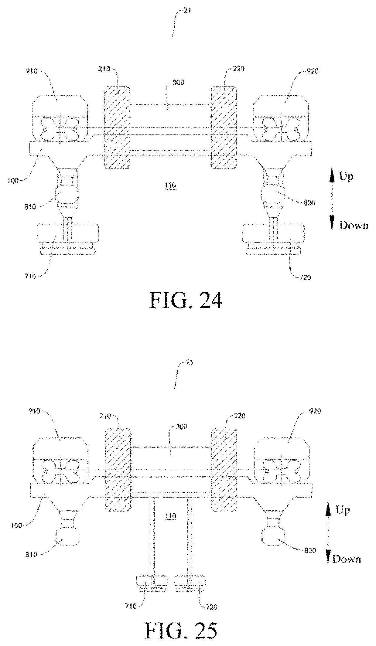
D00016

D00017

D00018

D00019

D00020

D00021
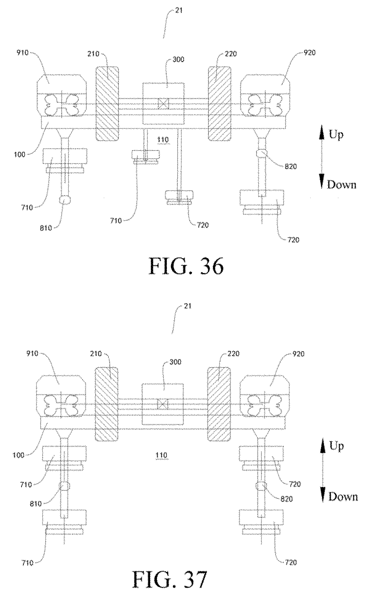
D00022
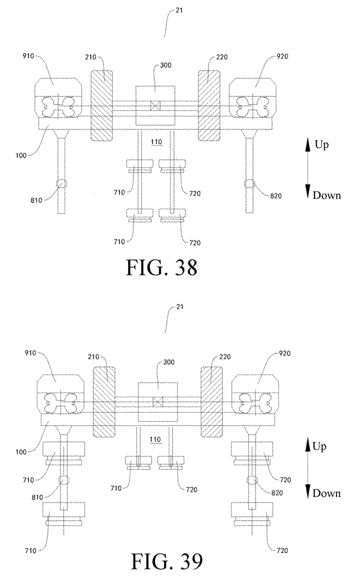
D00023
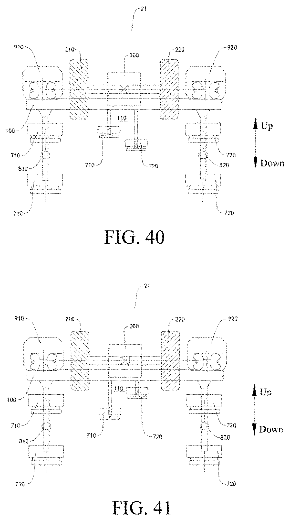
D00024

D00025

D00026

D00027
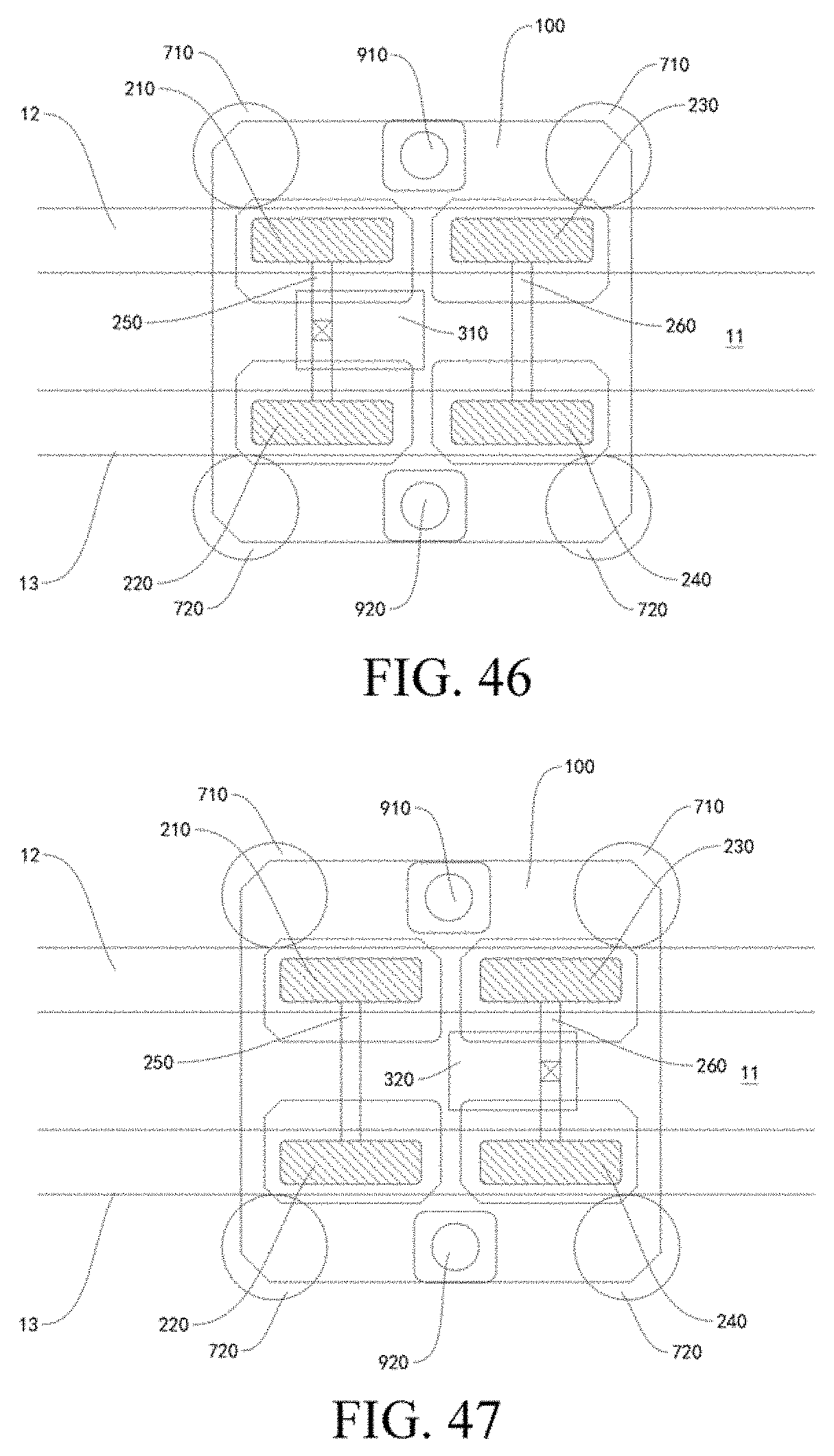
D00028
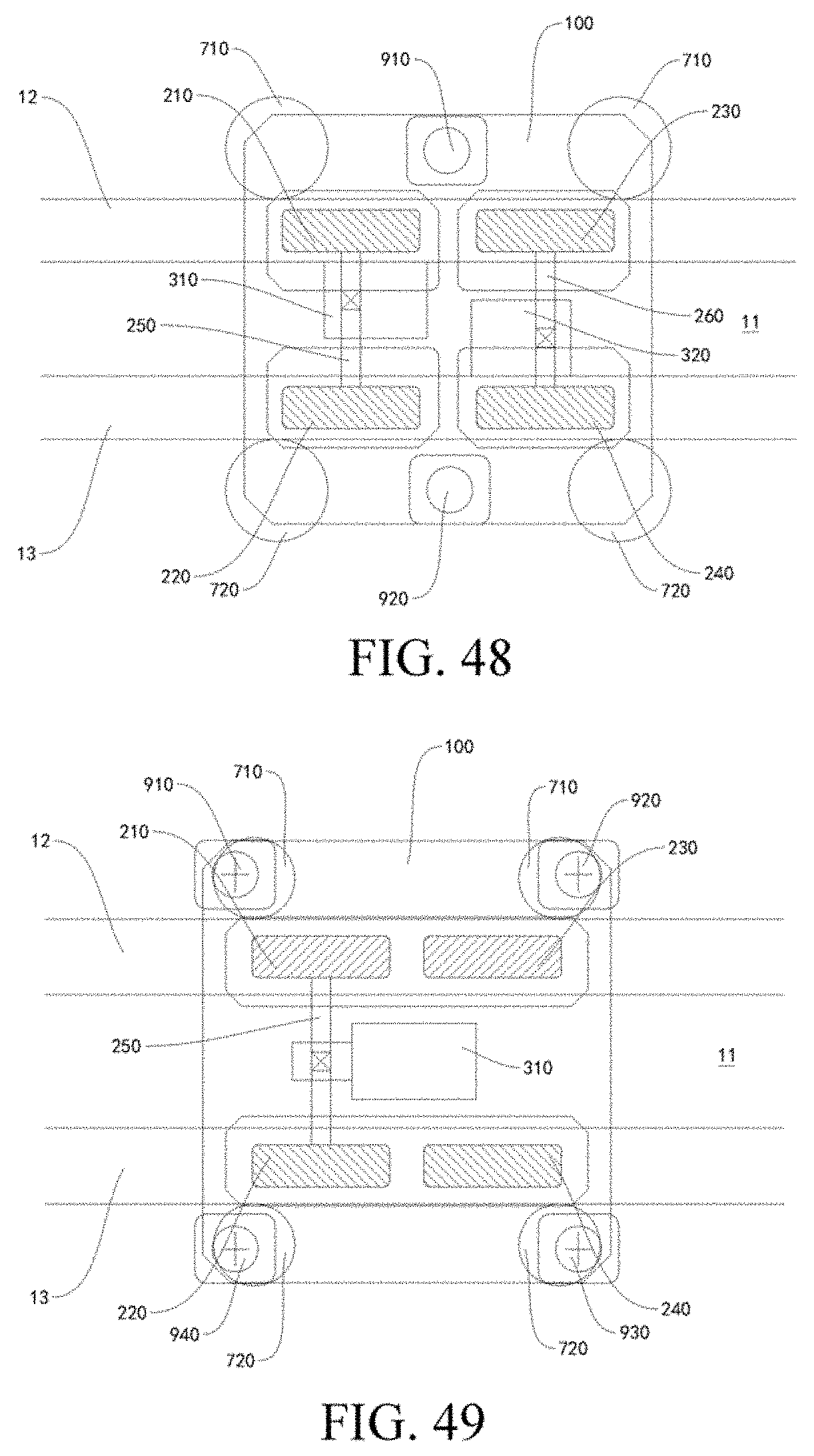
D00029
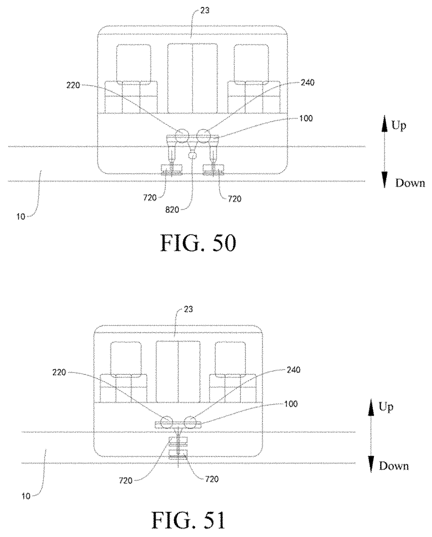
D00030
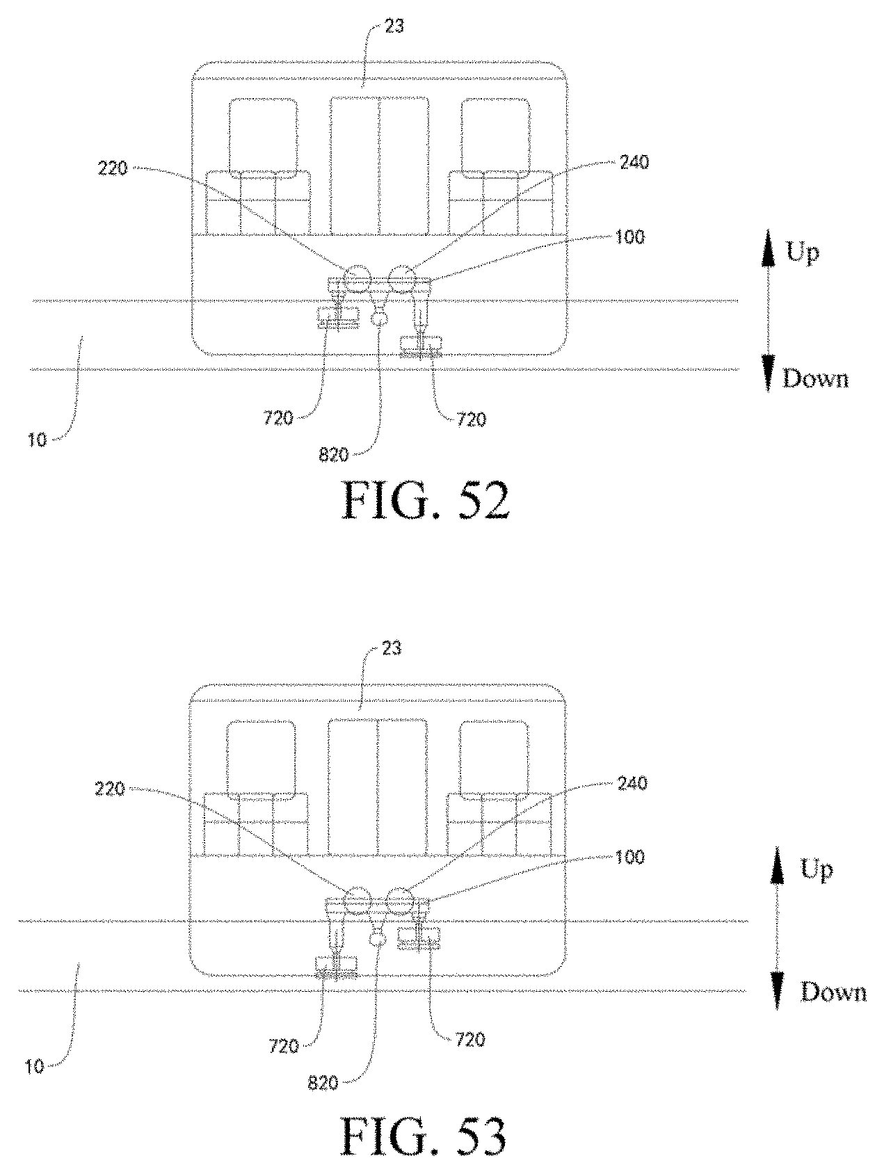
D00031

D00032

D00033

D00034

D00035

D00036

D00037

D00038
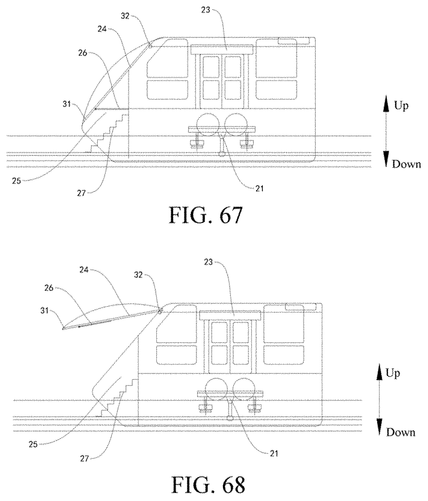
D00039
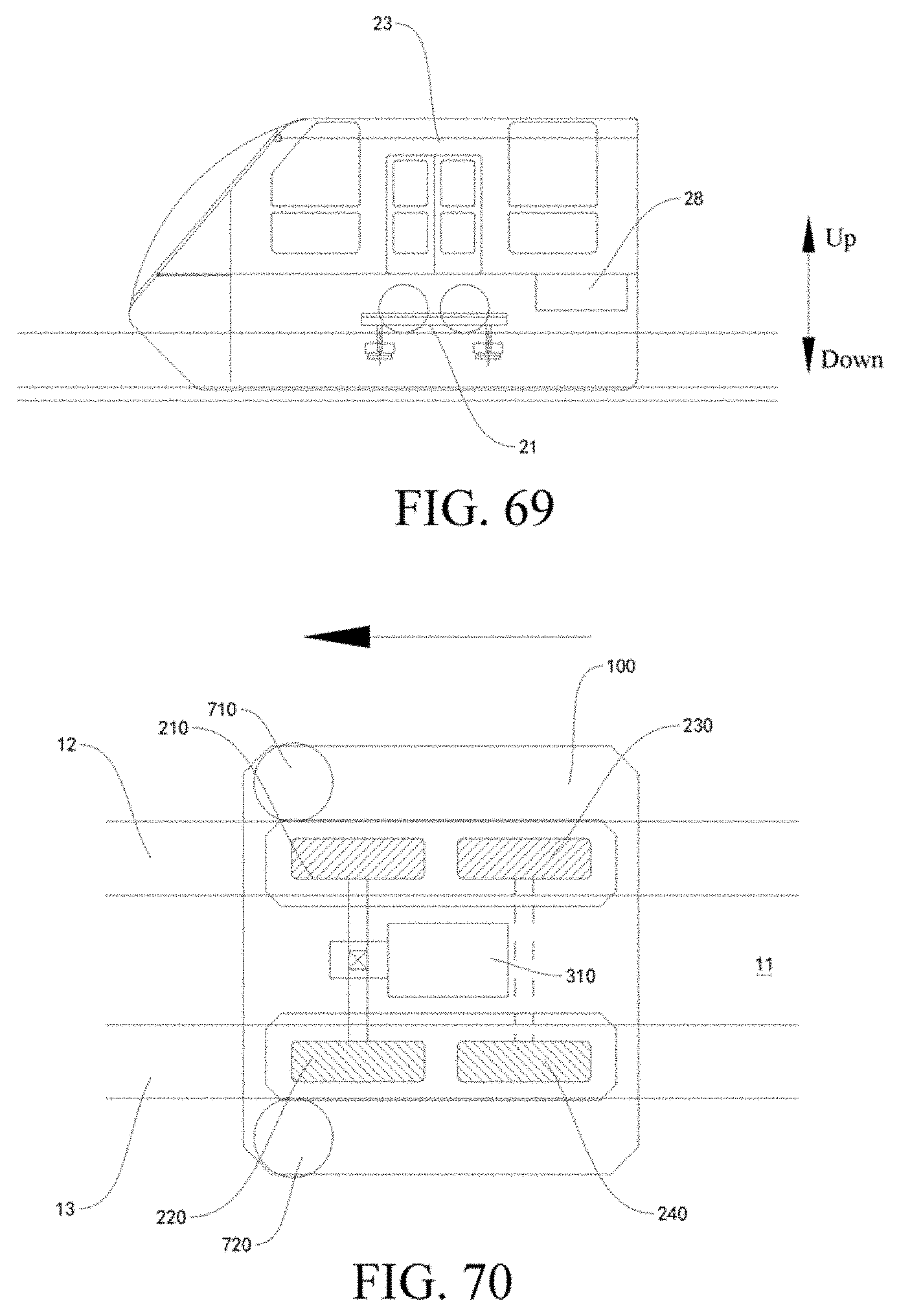
XML
uspto.report is an independent third-party trademark research tool that is not affiliated, endorsed, or sponsored by the United States Patent and Trademark Office (USPTO) or any other governmental organization. The information provided by uspto.report is based on publicly available data at the time of writing and is intended for informational purposes only.
While we strive to provide accurate and up-to-date information, we do not guarantee the accuracy, completeness, reliability, or suitability of the information displayed on this site. The use of this site is at your own risk. Any reliance you place on such information is therefore strictly at your own risk.
All official trademark data, including owner information, should be verified by visiting the official USPTO website at www.uspto.gov. This site is not intended to replace professional legal advice and should not be used as a substitute for consulting with a legal professional who is knowledgeable about trademark law.