Up-and-down Motion Mechanism For Belt Sander
Chang; Chin-Chin
U.S. patent application number 15/978186 was filed with the patent office on 2019-11-14 for up-and-down motion mechanism for belt sander. The applicant listed for this patent is Chin-Chin Chang. Invention is credited to Chin-Chin Chang.
| Application Number | 20190344397 15/978186 |
| Document ID | / |
| Family ID | 68463893 |
| Filed Date | 2019-11-14 |


| United States Patent Application | 20190344397 |
| Kind Code | A1 |
| Chang; Chin-Chin | November 14, 2019 |
UP-AND-DOWN MOTION MECHANISM FOR BELT SANDER
Abstract
An up-and-down motion mechanism for a belt sander including a continuous loop of sandpaper mounted on two end drums, includes a worktable including an opening with the belt sander moveably disposed therethrough, two bifurcations on an underside, and a housing mounted to the underside; a base releasably secured to the worktable; an electric motor in the housing and configured to repetitively move up-and-down relative to the worktable, the motor including an upper motor shaft rotatably connected to one drum, a lower worm screw, and two legs; and a transmitting assembly disposed in the housing and including a rotational shaft rotatably disposed through the legs, a worm wheel with the rotational shaft disposed through and meshing with the worm screw, two cams secured to two ends of the rotational shaft respectively, and two links each having one end connected to one arm and the other end connected to one bifurcation.
| Inventors: | Chang; Chin-Chin; (Taichung City, TW) | ||||||||||
| Applicant: |
|
||||||||||
|---|---|---|---|---|---|---|---|---|---|---|---|
| Family ID: | 68463893 | ||||||||||
| Appl. No.: | 15/978186 | ||||||||||
| Filed: | May 13, 2018 |
| Current U.S. Class: | 1/1 |
| Current CPC Class: | B24B 21/22 20130101; B24B 47/04 20130101 |
| International Class: | B24B 21/22 20060101 B24B021/22; B24B 47/04 20060101 B24B047/04 |
Claims
1. An up-and-down motion mechanism for a belt sander including a continuous loop of sandpaper mounted on two end drums, comprising: a detachable worktable including an opening with the belt sander up-and-down moveably disposed therethrough, two bifurcations on an underside, a housing mounted to the underside, a chute disposed under both one drum and the opening, and two cylindrical columns extending downward from the underside of the worktable; a base including a plurality of posts releasably secured to the underside of the worktable; a control device mounted to the base; an electric motor disposed in the housing and including an upper motor shaft rotatably connected to one drum, a lower worm screw, two legs, at least one first hollow cylindrical member slidably put on one cylindrical column, and at least one second hollow cylindrical member slidably put on the other cylindrical column; and a transmitting assembly disposed in the housing and including a rotational shaft rotatably disposed through the legs, a worm wheel with the rotational shaft disposed through and meshing with the worm screw, two cams secured to two ends of the rotational shaft respectively, two links with the electric motor disposed therebetween, each link having one end connected to one arm and the other end connected to one bifurcation, and a biasing member having one end anchored at a bottom of the electric motor and the other anchored at the underside of the worktable.
2. The up-and-down motion mechanism of claim 1, wherein in response to activating the electric motor, the worm screw rotates to rotate the worm wheel which in turn rotates the cams, the rotary motion of the worm wheel is transformed into linear motion of the links, and the electric motor repetitively moves up-and-down, thereby repetitively moving the belt sander up-and-down.
3. The up-and-down motion mechanism of claim 1, wherein the number of the post is four.
Description
BACKGROUND OF THE INVENTION
1. Field of the Invention
[0001] The invention relates to belt sanders and more particularly to an up-and-down motion mechanism for a belt sander, the up-and-down motion mechanism including an electric motor, two cams and a worm drive, so that a belt sander disposed above the motor may repetitively move up or down as the motor activates.
2. Description of Related Art
[0002] A conventional motion mechanism for a belt sander including a continuous loop of sandpaper mounted on two end drums and comprises an electric motor, a pivotal member, a link, and a reduction gear assembly. After activating the electric motor, the drums may move laterally due to operative cooperation of the motor shaft, the pivotal member, the link and the reduction gear assembly. As a result, the continuous loop of sandpaper may move laterally.
[0003] However, the conventional motion mechanism for a belt sander is disadvantageous because the movement of the belt sander is not smooth, its operation is not reliable, and the mechanism is complicated.
[0004] Thus, the need for improvement still exists.
SUMMARY OF THE INVENTION
[0005] It is therefore one object of the invention to provide an up-and-down motion mechanism for a belt sander including a continuous loop of sandpaper mounted on two end drums, comprising a detachable worktable including an opening with the belt sander up-and-down moveably disposed therethrough, two bifurcations on an underside, a housing mounted to the underside, a chute disposed under both one drum and the opening, and two cylindrical columns extending downward from the underside of the worktable;a base including a plurality of posts releasably secured to the underside of the worktable; a control device mounted to the base; an electric motor disposed in the housing and including an upper motor shaft rotatably connected to one drum, a lower worm screw, two legs, at least one first hollow cylindrical member slidably put on one cylindrical column, and at least one second hollow cylindrical member slidably put on the other cylindrical column; and a transmitting assembly disposed in the housing and including a rotational shaft rotatably disposed through the legs, a worm wheel with the rotational shaft disposed through and meshing with the worm screw, two cams secured to two ends of the rotational shaft respectively, two links with the electric motor disposed therebetween, each link having one end connected to one arm and the other end connected to one bifurcation, and a biasing member having one end anchored at a bottom of the electric motor and the other anchored at the underside of the worktable.
[0006] The above and other objects, features and advantages of the invention will become apparent from the following detailed description taken with the accompanying drawings.
BRIEF DESCRIPTION OF THE DRAWINGS
[0007] FIG. 1 is a perspective view of a belt sander incorporating an up-and-down motion mechanism according to the invention;
[0008] FIG. 2 is an exploded perspective view of FIG. 1;
[0009] FIG. 3 is an exploded perspective view of the components shown in top right corner of FIG. 2;
[0010] FIG. 4 is a perspective view of the motor mounted on the underside of the worktable, and the transmitting assembly mounted to the motor;
[0011] FIG. 5 is an exploded view of FIG. 4;
[0012] FIG. 6 is a perspective view of the motor and the transmitting assembly;
[0013] FIG. 7 is a view similar to FIG. 6 showing the meshing of the worm screw and the worm wheel and their rotations in operation;
[0014] FIG. 8 is an exploded perspective view of FIG. 7;
[0015] FIG. 9 is a side elevation schematically showing a downward motion of both the motor and the belt sander; and
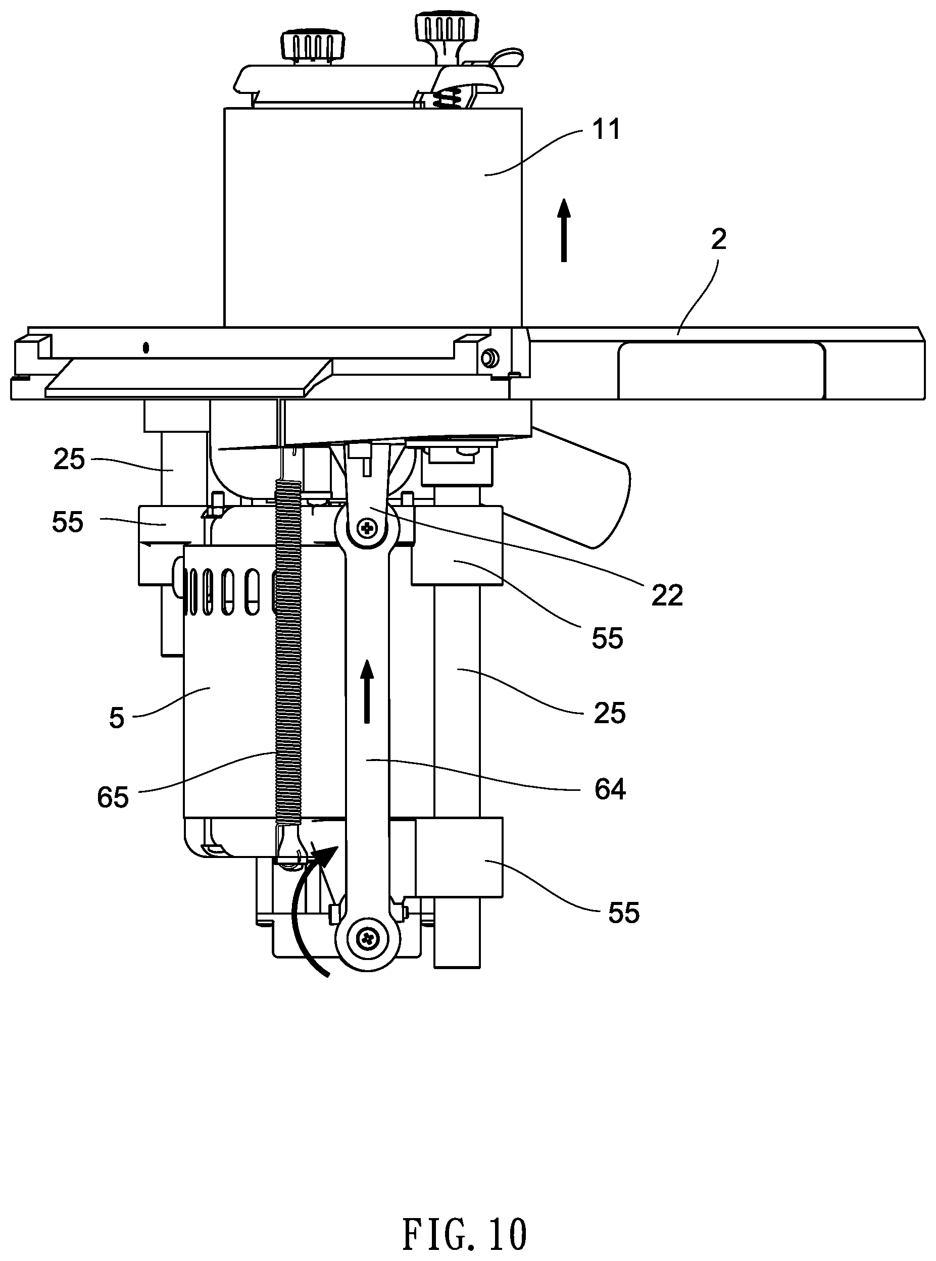
[0016] FIG. 10 is a view similar to FIG. 9 showing an upward motion of both the motor and the belt sander.
DETAILED DESCRIPTION OF THE INVENTION
[0017] Referring to FIGS. 1 to 10, an up-and-down motion mechanism for a belt sander 1 in accordance with the invention is shown. The belt sander 1 includes a continuous loop of sandpaper 11 mounted on two end drums 12. The up-and-down motion mechanism includes the following components as discussed in detail below.
[0018] A detachable worktable 2 includes an opening 21 with the belt sander 1 up-and-down moveably disposed therethrough, two bifurcations 22 on the underside, a housing 23 mounted to the underside with a portion of the opening 21 disposed thereabove, a chute 24 disposed under both one drum 12 and the opening 21, and two cylindrical columns 25 extending downward from the underside of the worktable 2.
[0019] A base 3 includes four posts 31 releasably secured to the underside of the worktable 2. A control device 4 mounted to the base 3.
[0020] An electric motor 5 is disposed in the housing 23 and includes an upper motor shaft 51 rotatably connected to one drum 12 via an adapter 54, a lower worm screw 52, two legs 53, and three hollow cylindrical members 55 in which one hollow cylindrical member 55 is slidably put on one column 25 and the other two hollow cylindrical members 55, aligned vertically, are slidably put on the other column 25. Both the motor shaft 51 and the worm screw 52 rotate at the speed as the motor 5 activates.
[0021] A transmitting assembly 6 is disposed in the housing 23 and includes a rotational shaft 61 rotatably disposed through the legs 53, a worm wheel 62 with the rotational shaft 61 disposed through and meshing with the worm screw 52 to transfer motion in 90-degree, two cams 63 secured to two ends of the rotational shaft 61 respectively, two links 64 with the motor 5 disposed therebetween, each link 64 having one end connected to one arm 63 and the other end connected to one bifurcation 22, and a torsion spring 65 having one end anchored at a bottom of the motor 5 and the other anchored at the underside of the worktable 2.
[0022] In response to activating the motor 5, the motor shaft 51 rotates and in turn, one drum 12 rotates. Thus, the continuous loop of sandpaper 11 shapes and finishes, for example wood. Generated sawdust is discharged to a collector (not shown) through the chute 24. The subject of the invention is discussed below.
[0023] The worm screw 52 rotates to rotate the worm wheel 62 which in turn rotates the cams 63. Further, the rotary motion of the worm wheel 62 is transformed into linear motion (i.e., repetitive up-and-down motion) of the links 64 due to the provision of the cams 63. Furthermore, the motor 5 is capable of repetitively moving up-and-down because the cylindrical members 55 are slidably put on the columns 25. As a result, the belt sander 1 repetitively moves up-and-down. This has the advantages of balancing the load of the continuous loop of sandpaper 11 and prolonging the useful life of the continuous loop of sandpaper 11. It is noted that the provision of the torsion spring 65 can assist in the returning of the motor 5 to its original position after being lowered or lifted.
[0024] While the invention has been described in terms of preferred embodiments, those skilled in the art will recognize that the invention can be practiced with modifications within the spirit and scope of the appended claims.
* * * * *
D00000
D00001
D00002
D00003
D00004
D00005
D00006
D00007
D00008
D00009
D00010
XML
uspto.report is an independent third-party trademark research tool that is not affiliated, endorsed, or sponsored by the United States Patent and Trademark Office (USPTO) or any other governmental organization. The information provided by uspto.report is based on publicly available data at the time of writing and is intended for informational purposes only.
While we strive to provide accurate and up-to-date information, we do not guarantee the accuracy, completeness, reliability, or suitability of the information displayed on this site. The use of this site is at your own risk. Any reliance you place on such information is therefore strictly at your own risk.
All official trademark data, including owner information, should be verified by visiting the official USPTO website at www.uspto.gov. This site is not intended to replace professional legal advice and should not be used as a substitute for consulting with a legal professional who is knowledgeable about trademark law.