Foley Catheter and Corresponding Single-Layer Tray Packaging System
Dickinson; Sarah ; et al.
U.S. patent application number 15/977944 was filed with the patent office on 2019-11-14 for foley catheter and corresponding single-layer tray packaging system. The applicant listed for this patent is Medline Industries, Inc. Invention is credited to Sarah Dickinson, Saul Godinez, Lindsay Hilbelink.
| Application Number | 20190344044 15/977944 |
| Document ID | / |
| Family ID | 68465021 |
| Filed Date | 2019-11-14 |


View All Diagrams
| United States Patent Application | 20190344044 |
| Kind Code | A1 |
| Dickinson; Sarah ; et al. | November 14, 2019 |
Foley Catheter and Corresponding Single-Layer Tray Packaging System
Abstract
A medical procedure kit includes a single-layer tray (100) having a first compartment (101) at least partially bounded by a first base member (107) and a second compartment (102) at least partially bounded by a second base member (108). At least one syringe (901) is situated within the first compartment. A Foley catheter (701), coupled to coiled tubing (702) and a fluid drain bag (703), is disposed within the second compartment. This catheter assembly is inverted, with the Foley catheter (701) and the coiled tubing (702) positioned between the second base member (108) and the fluid drain bag (703).
| Inventors: | Dickinson; Sarah; (Glen Ellyn, IL) ; Godinez; Saul; (Chicago, IL) ; Hilbelink; Lindsay; (Salem, WI) | ||||||||||
| Applicant: |
|
||||||||||
|---|---|---|---|---|---|---|---|---|---|---|---|
| Family ID: | 68465021 | ||||||||||
| Appl. No.: | 15/977944 | ||||||||||
| Filed: | May 11, 2018 |
| Current U.S. Class: | 1/1 |
| Current CPC Class: | A61M 25/0017 20130101; B65D 85/00 20130101; A61M 25/002 20130101 |
| International Class: | A61M 25/00 20060101 A61M025/00 |
Claims
1. A medical procedure kit, comprising: a single-layer tray comprising a first compartment at least partially bounded by a first base member and a second compartment at least partially bounded by a second base member; at least one syringe situated within the first compartment; a Foley catheter, coupled to coiled tubing and a fluid drain bag, disposed within the second compartment; wherein the Foley catheter and the coiled tubing are positioned between the second base member and the fluid drain bag.
2. The medical procedure kit of claim 1, wherein the Foley catheter is positioned between the coiled tubing and the second base member.
3. The medical procedure kit of claim 2, wherein the first compartment and the second compartment each define open top compartments.
4. The medical procedure kit of claim 3, the single-layer tray comprising a perimeter wall, the first compartment at least partially bounded by the perimeter wall.
5. The medical procedure kit of claim 3, the single-layer tray comprising a perimeter wall, the second compartment at least partially bounded by the perimeter wall.
6. The medical procedure kit of claim 3, wherein the at least one syringe comprises a first syringe and a second syringe.
7. The medical procedure kit of claim 6, the first compartment defining a lubricating jelly application chamber to lubricate at least a portion of the Foley catheter.
8. The medical procedure kit of claim 3, further comprising a third compartment bounded by a third base member.
9. The medical procedure kit of claim 8, further comprising a specimen jar positioned within the third compartment.
10. The medical procedure kit of claim 8, further comprising one or more swab sticks positioned within the third compartment.
11. A medical procedure kit, comprising: a single-layer tray comprising a first section, a second section, and a third section, each bounded by a base member; one or more partitions separating at least one of the first section, the second section, or the third section from another one of the first section, the second section, or the third section; a Foley catheter, coupled to coiled tubing and a fluid drain bag, disposed within the first section; wherein the Foley catheter and the coiled tubing are positioned between the base member of the first section and the fluid drain bag.
12. The medical procedure kit of claim 11, wherein the Foley catheter is positioned between the coiled tubing and the base member of the first section.
13. The medical procedure kit of claim 11, further comprising a syringe comprising lubricant, wherein the syringe comprising the lubricant is positioned in the second section.
14. The medical procedure kit of claim 13, further comprising one or more swabs positioned within the third section.
15. The medical procedure kit of claim 14, further comprising a specimen jar positioned within the third section.
16. The medical procedure kit of claim 15, wherein the third section comprises: a swab compartment including a well and one or more channels configured to respectively hold the one or more swabs therein; an overflow compartment fluidly connected to the well through the one or more channels; and a corner storage compartment.
17. The medical procedure kit of claim 16, wherein the specimen jar is positioned within the corner storage compartment.
18. A medical procedure kit, comprising: a single-layer tray comprising a compartment bounded at its bottom by a base member and a lubricating jelly application chamber; a container of lubricating jelly disposed within the single-layer tray; and a coiled tubing coupled between a Foley catheter and a drain bag, wherein the coiled tubing, the drain bag, and the Foley catheter are disposed within the compartment with the Foley catheter and the coiled tubing are positioned between the drain bag and the base member.
19. The medical procedure kit of claim 18, wherein the lubricating jelly application chamber is configured to lubricate at least a portion of the Foley catheter with the lubricating jelly.
20. The medical procedure kit of claim 18, wherein the Foley catheter is positioned between the coiled tubing and the base member.
Description
BACKGROUND
Technical Field
[0001] This disclosure relates generally to Foley catheters, and more particularly to Foley catheter packaging systems.
Background Art
[0002] Medical devices, including surgical instruments, supplies, and so forth, are generally shipped from manufacturer to medical services provider in sterile packaging. For example, a scalpel may be shipped to a surgeon in a plastic, vacuum-sealed, sterile package. Similarly, bandages may be shipped in paper, plastic, or paper composite sterile wrappers. When the medical services provider is ready to use the medical supply, the sterile package is removed. The medical services provider then uses the object in accordance with the procedure being performed.
[0003] While conventional packaging works well for objects having a generally unchanging form factor, special considerations have to be taken into consideration for some medical supplies. By way of example, Foley catheters and their corresponding tubing and other flexible equipment is generally shipped in a coiled configuration. Once the sterile packaging is removed, the tubing and other coiled materials must be uncoiled prior to use. Care must be taken in shipping, unwrapping, and using coiled assemblies. For instance, if a Foley catheter is inadvertently bent, kinked, or otherwise damaged, it may no longer be suitable for use. It would be advantageous to have an improved packaging system for Foley catheters.
BRIEF DESCRIPTION OF THE DRAWINGS
[0004] The accompanying figures, where like reference numerals refer to identical or functionally similar elements throughout the separate views and which together with the detailed description below are incorporated in and form part of the specification, serve to further illustrate various embodiments and to explain various principles and advantages all in accordance with the present disclosure.
[0005] FIG. 1 illustrates a top, front, right perspective view of one explanatory single-layer tray in accordance with embodiments of the disclosure.
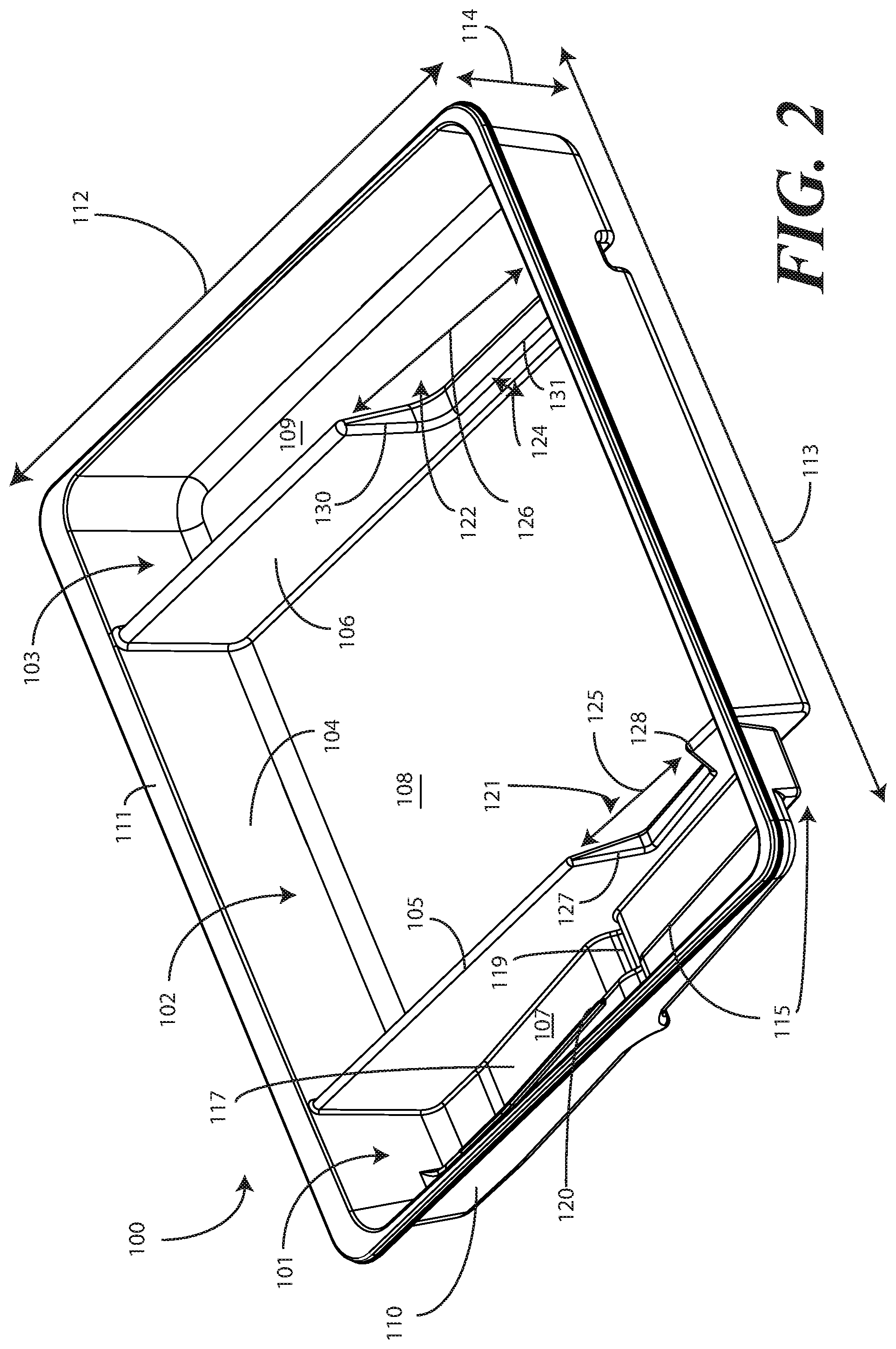
[0006] FIG. 2 illustrates a top, front, left perspective view of one explanatory single-layer tray in accordance with embodiments of the disclosure.
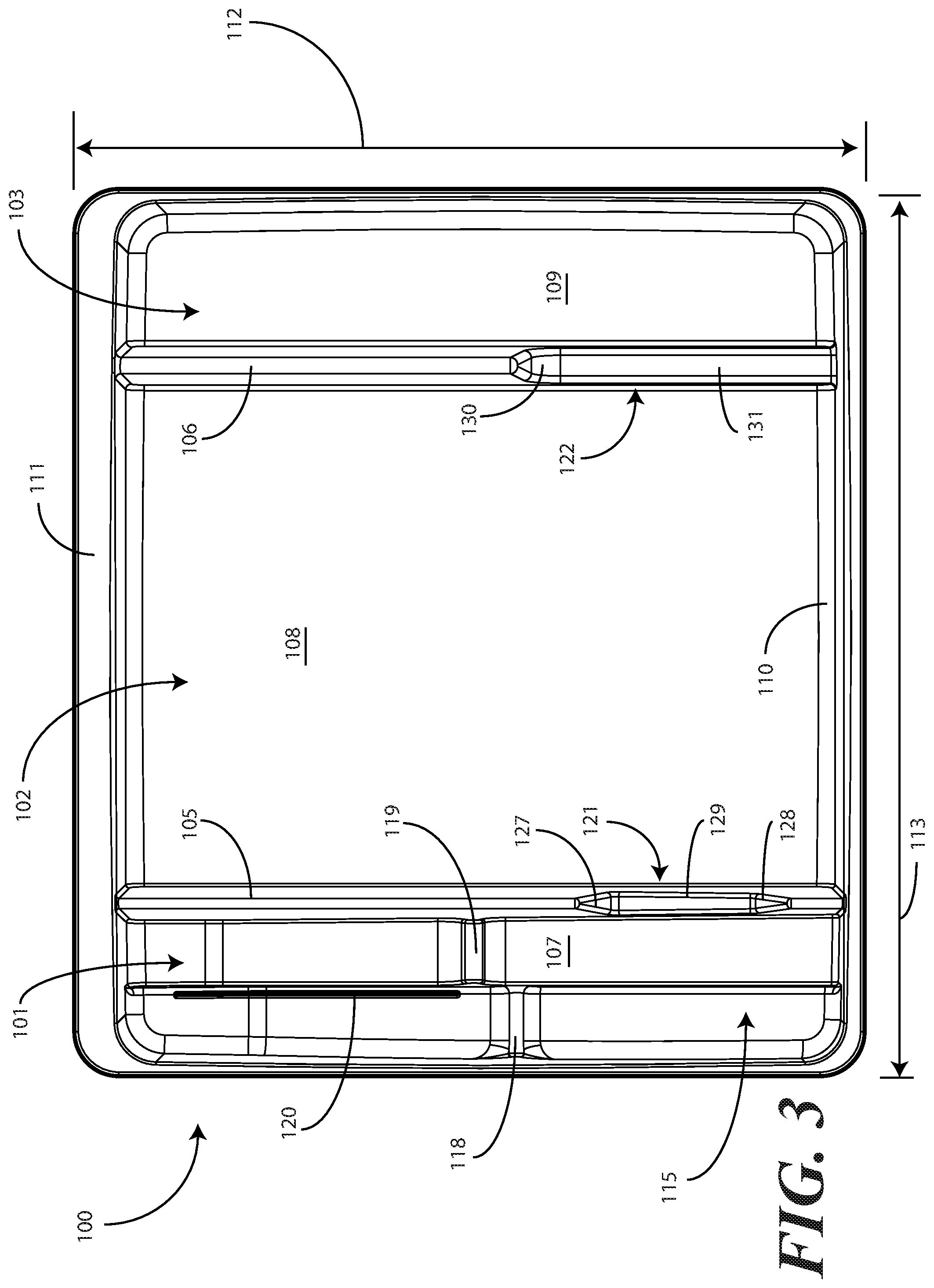
[0007] FIG. 3 illustrates a top plan view of explanatory single-layer tray in accordance with embodiments of the disclosure.
[0008] FIG. 4 illustrates a front elevation view of one explanatory single-layer tray in accordance with embodiments of the disclosure.
[0009] FIG. 5 illustrates a cut-away, left elevation view of one explanatory single-layer tray in accordance with embodiments of the disclosure.
[0010] FIG. 6 illustrates a bottom plan view of one explanatory single-layer tray in accordance with embodiments of the disclosure.
[0011] FIG. 7 illustrates a top plan view one explanatory Foley catheter, coiled tubing, and fluid drainage bag in accordance with one or more embodiments of the disclosure.
[0012] FIG. 8 illustrates a bottom plan view of one explanatory Foley catheter, coiled tubing, and fluid drainage bag in accordance with one or more embodiments of the disclosure.
[0013] FIG. 9 illustrates a top plan view of one explanatory single-layer tray, with a Foley catheter and corresponding procedural devices disposed therein, in accordance with one or more embodiments of the disclosure.
[0014] FIG. 10 illustrates a top plan view of another explanatory single-layer tray in accordance with one or more embodiments of the disclosure.
[0015] FIG. 11 illustrates a top plan view of another explanatory single-layer tray, with a Foley catheter and corresponding procedural devices disposed therein, in accordance with one or more embodiments of the disclosure.
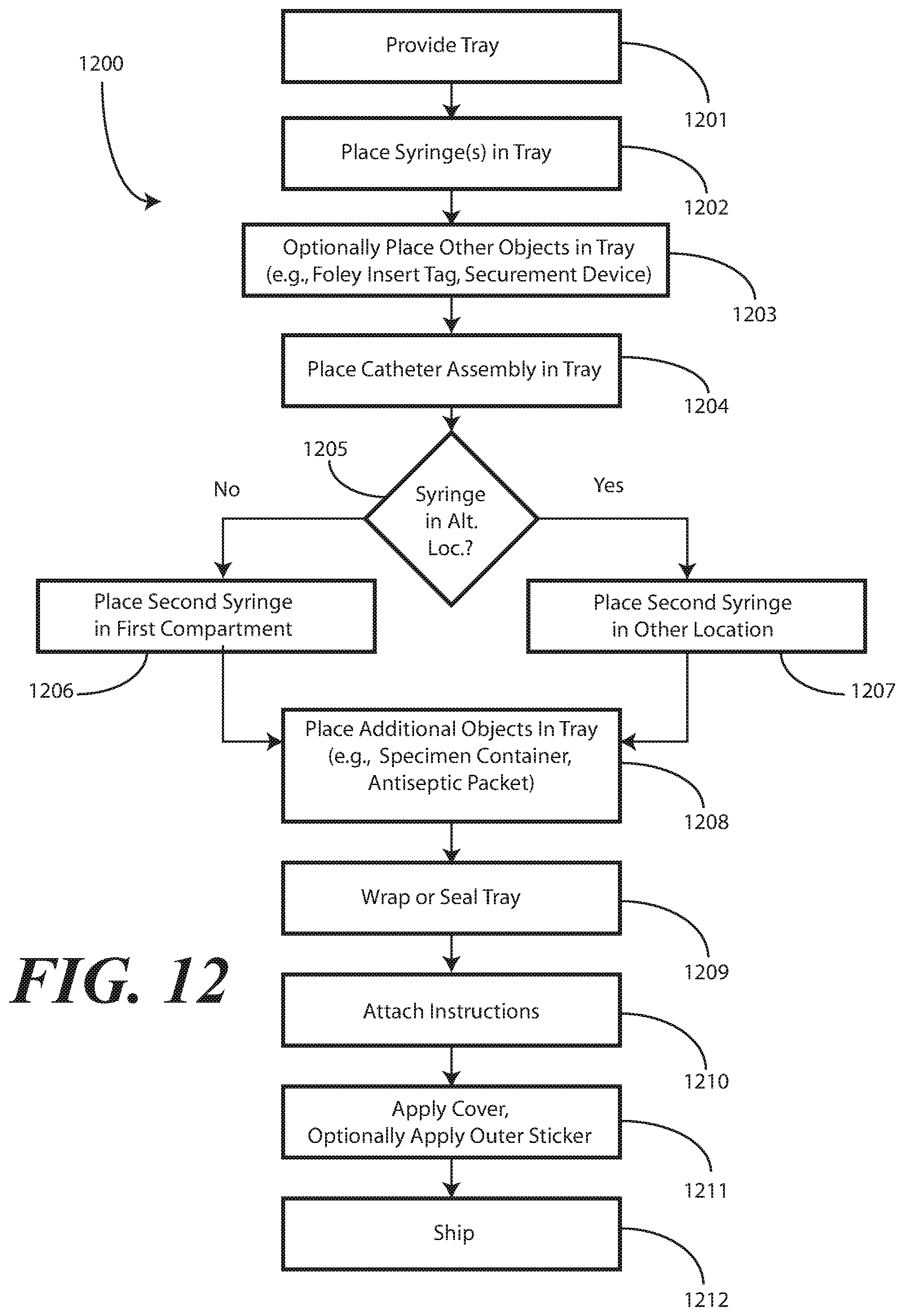
[0016] FIG. 12 illustrates one explanatory method in accordance with one or more embodiments of the disclosure.
[0017] FIG. 13 illustrates various embodiments of the disclosure.
[0018] Skilled artisans will appreciate that elements in the figures are illustrated for simplicity and clarity and have not necessarily been drawn to scale. For example, the dimensions of some of the elements in the figures may be exaggerated relative to other elements to help to improve understanding of embodiments of the present disclosure.
DETAILED DESCRIPTION OF THE DISCLOSURE
[0019] Before describing in detail embodiments that are in accordance with the present disclosure, it should be observed that the embodiments reside primarily in combinations of method steps and apparatus components related to packaging Foley catheters, their corresponding coiled tubing, fluid drain bags, and other components in a single-layer tray. Alternate implementations are included, and it will be clear that any method steps may be executed out of order from that shown or discussed, including substantially concurrently or in reverse order, depending on the desired application. Accordingly, the apparatus components and method steps have been represented where appropriate by conventional symbols in the drawings, showing only those specific details that are pertinent to understanding the embodiments of the present disclosure so as not to obscure the disclosure with details that will be readily apparent to those of ordinary skill in the art having the benefit of the description herein. Further, it is expected that one of ordinary skill, notwithstanding possibly significant effort and many design choices motivated by, for example, available time, current technology, and economic considerations, when guided by the concepts and principles disclosed herein will be readily capable of generating such assemblies and executing such method steps with minimal experimentation.
[0020] Embodiments of the disclosure are now described in detail. Referring to the drawings, like numbers indicate like parts throughout the views. As used in the description herein and throughout the claims, the following terms take the meanings explicitly associated herein, unless the context clearly dictates otherwise: the meaning of "a," "an," and "the" includes plural reference, the meaning of "in" includes "in" and "on." Relational terms such as first and second, top and bottom, and the like may be used solely to distinguish one entity or action from another entity or action without necessarily requiring or implying any actual such relationship or order between such entities or actions.
[0021] As used herein, components may be "operatively coupled" when information can be sent between such components, even though there may be one or more intermediate or intervening components between, or along the connection path. The terms "substantially" and "about" are used to refer to dimensions, orientations, or alignments inclusive of manufacturing tolerances. Thus, a "substantially orthogonal" angle with a manufacturing tolerance of plus or minus two degrees would include all angles between 88 and 92, inclusive. Also, reference designators shown herein in parenthesis indicate components shown in a figure other than the one in discussion. For example, talking about a device (10) while discussing figure A would refer to an element, 10, shown in figure other than figure A.
[0022] Embodiments of the disclosure provide a medical procedure kit comprising a single-layer tray. In one or more embodiments, the single-layer tray comprises a first compartment and a second compartment. The first compartment is at least partially bounded by a first base member in one or more embodiments. The second compartment is at least partially bounded by a second base member in one or more embodiments.
[0023] In one or more embodiments, at least one syringe is situated within the first compartment. In one or more embodiments, a Foley catheter is situated in the second compartment. In one or more embodiments, the Foley catheter is operatively coupled to coiled tubing. In one or more embodiments, the coiled tubing is operatively coupled to a fluid drain bag. In one or more embodiments where the Foley catheter is disposed in the second compartment, the operatively coupled coiled tubing and fluid drain bag are also disposed within the second compartment.
[0024] In one or more embodiments, to provide additional protection for the Foley catheter and to further help ensure it remains sterile when the medical procedure kit is opened, the Foley catheter is placed at the bottom of the second compartment, with the operatively coupled coiled tubing and the operatively coupled fluid drain bag situated atop the Foley catheter. Said differently, in one or more embodiments, the Foley catheter and the coiled tubing are positioned between the second base member and the fluid drain bag. In one or more embodiments, the Foley catheter is positioned between the coiled tubing and the second base member.
[0025] Embodiments of the present disclosure further provide a medical procedure kit that includes medical products for performing a medical procedure. In one embodiment, the medical procedure kit is configured for a Foley catheterization procedure. Such an embodiment will be used herein for illustration purposes. However, it will be clear to those of ordinary skill in the art having the benefit of this disclosure that embodiments of the disclosure are not so limited. Other medical procedure kits for performing other procedures could be substituted for the illustrative Foley catheterization procedure kit disclosed herein by substituting other medical implements for the Foley catheterization implements.
[0026] When a Foley catheter assembly is inserted into a patient, sterile water may be used to inflate the balloon of the Foley catheter. Additionally, the Foley catheter may be coated in a lubricating jelly prior to insertion into the patient. Fluids and other samples may then be monitored and obtained from the patient as they pass into the Foley catheter, through the coiled tubing (which may be uncoiled at this point) and into a syringe via a Luer access port or into the fluid drain bag. Embodiments of the present disclosure provide a single-layer tray configured to accommodate not only the Foley catheter, the operatively coupled coiled tubing, and the operatively coupled fluid bag, but also syringes containing fluids such as sterile water or aqueous lubricants. Further, the single-layer tray can accommodate a sterile specimen jar for capturing samples taken from the patient as they pass into the Foley catheter, through the coiled tubing (which may be uncoiled at this point) and into a syringe via a Luer access port or into the fluid drain bag.
[0027] In addition to simply accommodating these corresponding medical devices, in one or more embodiments the single-layer tray is configured to provide the medical services provider with mnemonic devices instructing them in which order to use each device. For example, a compartment containing syringes, in one embodiment, includes a base member that presents each syringe at, for example, an easy to reach angle and/or at different heights based upon order in which each syringe is used in a Foley catheterization procedure.
[0028] Another advantage of embodiments of the present disclosure is that compartments have multi-purpose functionality. For example, in one embodiment, a compartment configured to accommodate a syringe having lubricating jelly disposed therein is also configured to be used as a lubricating jelly applicator or lubricating jelly application compartment. In one or more embodiments, a medical services provider first dispenses the lubricating jelly into the compartment from which the syringe was taken. The medical services provider then passes at least a tip of the Foley catheter from the second compartment into the first compartment and into the lubricating jelly. Advantageously, the tray not only serves as a shipping and storage container for an assembly of devices used with a Foley catheter procedure, but also as an application device to assist a medical services provider in using those products together, and without compromising the sterile field required for proper aseptic technique.
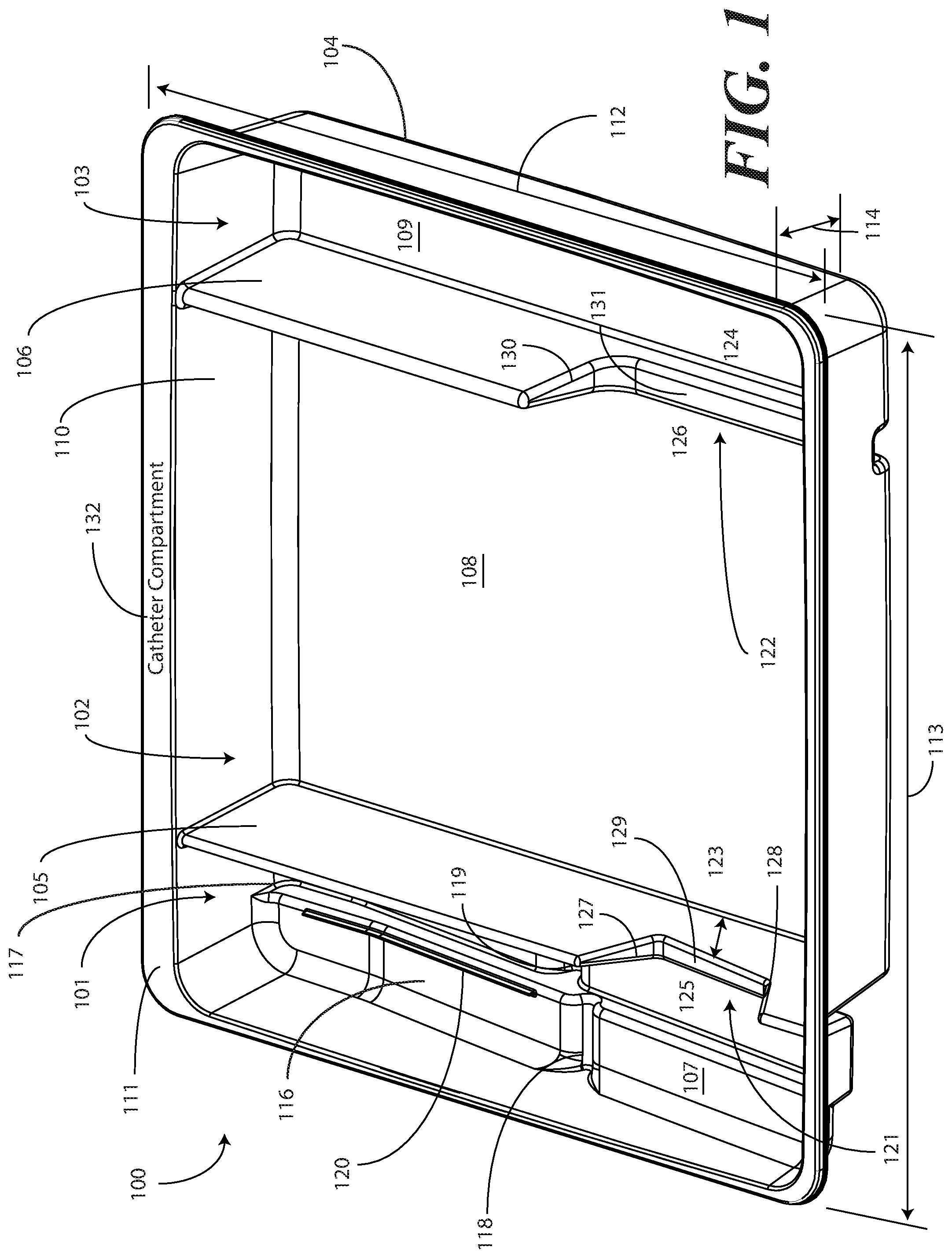
[0029] Turning now to FIGS. 1-6, illustrated therein are views of one embodiment of a single-layer tray 100 configured to accommodate a Foley catheter, its operatively coupled coiled tubing, and its operatively coupled fluid drain bag in accordance with one or more embodiments of the disclosure. FIG. 1 illustrates a top, front right perspective view of the single-layer tray 100. FIG. 2 illustrates a top, front, left perspective view of the single-layer tray 100. FIG. 3 illustrates a top plan view of the single-layer tray 100. FIG. 4 illustrates a front elevation view of the single-layer tray 100. FIG. 5 illustrates a cut-away, left elevation view of one embodiment of a single-layer tray 100. Likewise, FIG. 6 illustrates a bottom plan view of the single-layer tray 100. For simplicity of discussion, these figures will be referred to collectively with like reference numerals referring to identical or functionally similar elements throughout the separate views.
[0030] The single-layer tray 100, in one embodiment, is formed by a contoured surface 104 that defines the various features and compartments of the single-layer tray 100. The contoured surface 104 of the single-layer tray 100 can be manufactured in various ways. For example, in one embodiment, the single-layer tray 100 can be thermally formed on a mold from a soft thermoplastic, such as styrene or polystyrene. In another embodiment, the single-layer tray 100 can be injection molded. In another embodiment, the tray can be poured on a mold using a quick setting plastic, epoxy, or resin. Other methods of manufacture will be obvious to those of ordinary skill in the art having the benefit of this disclosure.
[0031] Exemplary dimensions for one embodiment of the single-layer tray 100 are as follows: The length 112 can be between nine and twelve inches, such as ten inches. One illustrative length 112 may be 10.380 inches. Similarly, the width 113 can be between eight and eleven inches, such as nine inches. One illustrative width 113 is 9.250 inches. The height 114 can be between one and three inches. One illustrative height 114 is 1.750 inches.
[0032] In one embodiment, the single-layer tray 100 includes three main compartments: a first compartment 101, a second compartment 102, and a third compartment 103. The first compartment 101 is separated from the second compartment 102 by a first barrier 105. The second compartment 102 is separated from the third compartment 103 by a second barrier 106.
[0033] In one embodiment, the compartments are open from the top of the single-layer tray 100--the top being opposite the base members of the single-layer tray 100--and are bounded on the bottom by a first base member 107, a second base member 108, and a third base member 109. The compartments are bounded on the sides by a perimeter wall 110. In the illustrative "open top" embodiment of FIG. 1, the perimeter wall 110 ends in a horizontal flange 111 extending substantially orthogonally from the perimeter wall 110. It will be clear to those of ordinary skill in the art having the benefit of this disclosure that embodiments other than that shown in FIG. 1 are possible without departing from the spirit and scope of the disclosure. For instance, the top of the single-layer tray 100 could have a hinged or snap-coupled lid that is opened or removed to reveal the compartments there beneath. Similarly, in one or more embodiments the horizontal flange 111 can be omitted, with each of the first compartment 101, the second compartment 102, and the third compartment 103 being bounded by a wall, be it the perimeter wall 110 or another wall, that extends distally from the various base members 107,108,109 to a terminating edge.
[0034] In one illustrative embodiment, the single-layer tray 100 is configured to hold or otherwise accommodate all of the necessary devices and materials to perform a Foley catheter-based procedure on a patient. Said differently, in one or more embodiments, the single-layer tray 100 is configured to hold not only the Foley catheter, its operatively coupled coiled tubing, and its operatively coupled fluid drain bag, but the medical devices corresponding to Foley catheter use as well. Using one illustrative procedure as an example, the following devices will be used: a syringe holding sterile water, a syringe holding lubricating jelly or another equivalent lubricant, a catheter assembly, skin cleansing or preparation materials, and a specimen jar. The various compartments and features of the single-layer tray 100 shown in FIGS. 1-6 will be described for use with these devices. As will be described in more detail below with reference to FIG. 9, additional objects can be included with the tray, such as one or more towels, a drape to cover the patient, rubber gloves, hand sanitizing materials, swab sticks, a securement device, a Foley insert tag, a printed instruction pamphlet, and so forth. The syringe holding sterile water, syringe holding lubricating jelly, the Foley catheter, its operatively coupled coiled tubing, and its operatively coupled fluid drain bag, and specimen jar are used for illustration purposes only, as it will be clear that other objects may be added to or substituted for these objects. Further, subsets of these objects may be used.
[0035] In one embodiment suitable for procedures using the syringe holding sterile water, syringe holding lubricating jelly, the Foley catheter, its operatively coupled coiled tubing, and its operatively coupled fluid drain bag, and specimen jar, the single-layer tray 100 is configured such that these objects are ordered in accordance with their order of use during the Foley catheterization procedure. For example, in one embodiment the single-layer tray 100 includes a first compartment 101 for accommodating one or more syringes, a second compartment 102 for accommodating the Foley catheter, its operatively coupled coiled tubing, and its operatively coupled fluid drain bag, and optionally one or more syringes, and a third compartment 103 for accommodating at least the specimen jar. These devices stowed in the various compartments will be illustrated and described with respect to FIG. 9 below. The discussion of FIGS. 1-6 will include the features of the single-layer tray 100 that make the single-layer tray 100 suitable for accommodating these devices.
[0036] For example, in one embodiment the first compartment base member 107 is contoured. Illustrating by example, the first compartment base member 107 can include features that hold any syringes stored within the first compartment 101 at different heights. In this illustrative embodiment, the first compartment base member 107 includes a stair-stepped contour 115 suitable that supports syringes at different heights.
[0037] Illustrating by example, a first step portion 116 of the stair-stepped contour 115 may be at a different height within the single-layer tray 100 than a second step portion 117 of the stair-stepped contour 115. In the illustrative embodiment of FIGS. 1-6, the first step portion 116--which is disposed farther from the first barrier 105 than the second step portion 117--is shallower than the second step portion 117. Said differently, the second step portion 117 is disposed at a greater depth within the single-layer tray 100 than the first step portion 116.
[0038] The contours of the first compartment 101 can serve as mnemonic device when for medical implements stored within the first compartment 101. For example, it may be intuitive that a higher syringe may need to be used first. Accordingly, placing this "first to be used" syringe on a higher step portion will indicate that this syringe should to be used first. This intuition is further enforced when the higher position is situated farther to the left in a left-to-right usage, i.e., like reading a book, configuration. Thus, a user receives a mnemonic reminder to use a syringe disposed on the first step portion 116 prior to a syringe disposed on the second step portion 117, as it is both higher and farther to the left.
[0039] Where syringes are stowed in the first compartment 101, the first compartment base member 107 can further be configured for syringe ease of use. For example, in one embodiment the first compartment base member 107 is inclined relative to other compartment base members. In the illustrative embodiment of FIGS. 1-6, the second compartment base member 108 and third compartment base member 109 are substantially coplanar with each other. Further, the second compartment base member 108 and third compartment base member 109 are generally flat in these views, although it will be clear to those of ordinary skill in the art having the benefit of this disclosure that contours could be incorporated into one or both of these base members. Illustrating by example, the first compartment base member 107 could be substantially flat.
[0040] In this illustrative embodiment, however, the first compartment base member 107 is configured to be inclined relative to one or both of the second compartment base member 108 and third compartment base member 109. As such, the stair-stepped contour 115 forms a ramp upon which syringes may be placed so that the plunger of each syringe is predisposed to project upward and out of the single-layer tray 100. Said differently, the stair-stepped contour 115 is configured such that the first step portion 116 and the second step portion 117 are disposed in a non-parallel orientation relative to the second compartment base member 108. This configuration makes it easier for a medical services provider to grasp the syringes and remove them from the single-layer tray 100.
[0041] The first compartment base member 107 may include other features suitable for accommodating one or more syringes as well. In one embodiment, any of the first compartment base member 107, the first step portion 116, or the second step portion 117 can include recesses 118,119 for accommodating a syringe flange. These recesses 118,119 generally function to prevent the syringes from sliding lengthwise within the first compartment 101. Similarly, in one embodiment any of the first compartment base member 107, the first compartment sidewalls, the first step portion 116, or the second step portion 117 include protrusions 120 that help to prevent the syringes from sliding laterally within the first compartment 101.
[0042] In one embodiment, one or both of the first barrier 105 and the second barrier 106 include optional openings disposed therein. In the illustrative embodiment shown in FIGS. 1-6, the first barrier 105 includes a first opening 121 between the first compartment 101 and the second compartment 102. Similarly, the second barrier 106 includes a second opening 122 between the second compartment 102 and the third compartment 103. Each of these openings has an opening depth associated therewith. Similarly, each opening has an opening width associated therewith. In the illustrative embodiment of FIGS. 1-6, the first opening 121 is bounded by a first opening base member 129 and two inclined first opening side members 127,128, while the second opening 122 is bounded by a second opening base member 131, an inclined second opening side member 130, and the perimeter wall 110.
[0043] While the opening depths can be the same, in one embodiment the opening depths are different. For example, in the illustrative embodiments of FIGS. 1-6, the first opening 121 has a first opening depth 123 that is less than the second opening depth 124 of the second opening 122. Similarly, in one embodiment the opening widths are different. For example, in the illustrative embodiments of FIGS. 1-6, the first opening 121 has a first opening width 125 that is less than the second opening width 126 of the second opening 122. Such a disparity in opening depths and widths, as well as the inclusion of inclined opening side members, provides an advantage in some applications.
[0044] For instance, in many Foley catheter procedures a pair of syringes--such as syringes having a one-half inch diameter--fits easily into the first compartment 101 when the single-layer tray 100 is made with the illustrative dimensions set forth above. However, some procedures require one or more of the syringes to be larger. Additionally, in still other procedures syringes are used in different orders. Where syringes that are larger in diameter are required, these larger syringes are capable of nesting within the first opening 121 and second opening 122. The inclined opening side members prevent the syringe from moving lengthwise, while the disparate opening heights present the plunger of the syringe to the medical services provider for easy removal from the single-layer tray 100. Where the syringes are used in different orders, or simply for design choice, one syringe can be placed in the first compartment 101, while another syringe can be placed in the second compartment 102, and so forth.
[0045] The stair-stepped contour 115, working in tandem with the first opening 121, gives the tray additional advantages over prior art catheter containers. For instance, the first compartment base member 107 allows the first compartment 101 to be used as a lubricant applicator for the catheter.
[0046] Specifically, the medical services provider may dispense the lubricating jelly into the first compartment 101 after removing the syringes therefrom. In one embodiment, this lubricating jelly is dispensed along the second step portion 117. Where included, and where lower than the first step portion 116, the second step portion 117 serves as a channel in which the lubricating jelly may spread. A medical services provider may then pass the at least a tip of the Foley catheter from the first compartment 101 into the second compartment 102, optionally through the first opening 121, and into the lubricating jelly. In one or more embodiments, the tip or more of the Foley catheter passes through the channel formed by the second step portion 117, i.e., along the second step portion 117 through the dispensed lubricating jelly. From there, the Foley catheter is passed out the top of the single-layer tray 100 to the patient.
[0047] This feature of the single-layer tray 100 greatly eases the application of lubricating jelly to the catheter when compared to prior art solutions. In one embodiment, the single-layer tray 100 is packaged with printed instructions showing the medical services provider how to apply lubricating jelly in this manner.
[0048] It will be clear to those of ordinary skill in the art having the benefit of this disclosure that alternative methods may be used to apply the lubricating jelly as well. For example, in another embodiment, the lubricating jelly is dispensed directly onto the Foley catheter and/or its operatively coupled tubing while these components are situated in or above either the first compartment 101 or the second compartment 102. Excess lubricant falling from the catheter tubing can then collect, and be retained, in any of the first compartment 101, the second step portion 117 of the first compartment 101, or the second compartment 102.
[0049] This particular feature highlights another advantage of the "compartmentalized" structure of various embodiments of the disclosure. As the single-layer tray 100 includes multiple compartments, various tasks associated with a Foley catheterization procedure can be completed while keeping the Foley catheter within the single-layer tray 100. The ability to keep the catheter in the single-layer tray 100 reduces the risk that the Foley catheter, its operatively coupled coiled tubing, and its operatively coupled fluid drain bag, or corresponding devices, will be contaminated with bacteria or microbes on other objects within the procedure room.
[0050] Illustrating by example, when the first compartment 101 is used to apply lubricating jelly to the Foley catheter or its operatively coupled coiled tubing, the lubricating jelly can be applied while these components are completely contained within the confines of the single-layer tray 100. Advantageously, this reduces the risk that the Foley catheter or its operatively coupled coiled tubing will become contaminated. This correspondingly reduces the risk of infection for the patient receiving the catheter.
[0051] Prior art systems, for example such as those in which the catheterization procedure components are shipped in separate and/or stacked containers, may contribute to substandard techniques in that the catheter can become contaminated when moving it from its shipping container. Consequently, the patient can be at an elevated risk of infection as the catheter is moved from one tray to another. Embodiments of the present disclosure solve this problem by providing a single-layer tray 100 with compartments. Further, in one embodiment the first compartment 101 allows the Foley catheter can stay in place during and after lubrication. By having easy access to the components disposed in the single-layer tray 100, the medical services provider can more easily prepare and use the components within the single-layer tray 100. This helps to minimize the risk of contaminating the patient or the sterile field during the procedure.
[0052] In one embodiment, the second step portion 117 is configured to be inclined at a shallower angle than the first step portion 116 in at least a portion opposite the recess 119 from the first opening 121. When configured in such a fashion, the second step portion 117 includes a "cutdown" so that the catheter can stay within the channel both during and after lubrication.
[0053] Additionally, the Foley catheter can be placed in both the first opening 121 and second opening 122 during lubrication. When positioned in this configuration, the second opening 122 helps to align the catheter with the first opening for easy passage through the lubrication channel formed by the second step portion 117.
[0054] The single-layer tray 100 of FIGS. 1-6 includes additional advantages over prior art catheter packaging as well. For example, in one embodiment, instructions 132 or other graphical indicia can be printed, placed upon, or molded into the tray. In this illustrative embodiment, the graphical indicia are molded into the horizontal flange 111. However, it can be molded into other portions of the single-layer tray 100, including the base members of the compartments, along the barriers, and so forth. In one embodiment, compartment designations can be placed above each compartment to ensure the medical services provider uses the correct device or material at the correct time. In another embodiment, expiratory dates for materials or devices disposed within the single-layer tray 100 may be molded into portions of the single-layer tray 100.
[0055] It will be obvious to those of ordinary skill in the art having the benefit of this disclosure that the disclosure is not so limited. Any number of various text or picture combinations can be printed on, placed upon, or molded into various parts of the tray. For instance, graphical indicia can be applied to the compartment base members in addition to the horizontal flange 111. Note that the horizontal flanges, in one embodiment, can terminate in downwardly protruding vertical flanges for increased stability during the printing process.
[0056] Another advantage of the single-layer tray 100 is that its compartmentalized configuration helps to reduce the risk of contaminating a patient or compromising the sterile nature of the components stored in the single-layer tray 100. Since Foley catheter, its operatively coupled coiled tubing, and its operatively coupled fluid drain bag, and medical devices corresponding to Foley catheter use, are stored within the same single-layer tray 100, the risk of cross-contamination between sterile work areas and non-sterile spaces is minimized. Further, by having the Foley catheter, its operatively coupled coiled tubing, and its operatively coupled fluid drain bag, and the devices corresponding to catheter use stowed in a one-level tray rather than a multi-level, stacked configuration, the medical services provider can more easily prepare and use the catheter and corresponding devices disposed within the single-layer tray 100.
[0057] Turning now to FIG. 7, illustrated therein is one explanatory embodiment of a catheter assembly 700 configured in accordance with one or more embodiments of the disclosure. In one or more embodiments, the catheter assembly 700 comprises a Foley catheter 701, its operatively coupled coiled tubing 702, and its operatively coupled fluid drain bag 703. As shown in FIG. 7, the coiled tubing 702 is coupled between the Foley catheter 701 and the fluid drain bag 703.
[0058] A clip or other hanger 704 can be coupled to the fluid drain bag 703 so that the fluid drain bag 703 can be coupled to a stand, bedrail, or other object. In one or more embodiments the coiled tubing 702 may be coupled to the Foley catheter 701, and the fluid drain bag 703 coupled to the coiled tubing 702, before the assembly is placed in a tray. Alternatively the Foley catheter 701, the coiled tubing 702, and the fluid drain bag 703 can be separately stored in a tray, with each being coupled together once the tray is opened.
[0059] In one or more embodiments, the Foley catheter 701 includes an inflation port 705. A syringe containing sterile water or other fluid can be coupled to the inflation port 705. The sterile water or other fluid can be injected into the inflation port 705 so that the balloon of the Foley catheter 701 can be inflated. The Foley catheter 701 also includes a drainage port 706, which is operatively coupled to the coiled tubing 702.
[0060] The Foley catheter 701 is suitable for insertion into the urethra of a patient. In one or more embodiments, the Foley catheter 701 is an elongated, flexible device. The Foley catheter 701 can be manufactured from flexible material such as polymers, elastomers, flexible steel, or other materials. Other materials suitable for manufacturing the Foley catheter 701 will be obvious to those of ordinary skill in the art having the benefit of this disclosure.
[0061] In one or more embodiments, the Foley catheter 701 includes an insertion end and a second end, which is coupled to the coiled tubing 702 in one or more embodiments. A central lumen passes through the Foley catheter 701 so that fluids may pass from the insertion end to the second end, through the operatively coupled coiled tubing 702, and into the fluid drain bag 703.
[0062] When inserted into a patient, an inflatable retaining balloon (not shown) operatively coupled to the Foley catheter 701 can be inflated using the inflation port 705 to retain the Foley catheter 701 within the patient. In one or more embodiments, a balloon is inflated with sterile water to retain the insertion end of the Foley catheter 701 within the patient's bladder.
[0063] Turning now to FIG. 8, illustrated therein is the catheter assembly 700 turned upside down. As shown, the coiled tubing 702 is disposed between the Foley catheter 701 and the fluid drain bag 703. Embodiments of the disclosure contemplate that inverting the catheter assembly 700 prior to placing the same in a tray offers numerous advantages. First, having the fluid drain bag 703 as the outer-most component provides an additional protective layer for both the coiled tubing 702 and the Foley catheter 701. This additional protective layer helps to ensure that the coiled tubing 702 and the Foley catheter 701 remain sterile, even after the packaging or tray is opened.
[0064] Second, inverting the catheter assembly 700 allows the fluid drain bag 703 to be removed from the tray or packaging first, and without disturbing the coiled tubing 702 and the Foley catheter 701. This provides more workspace within the tray or packaging for a medical services provider. Additionally, since the fluid drain bag 703 need not remain sterile, removing it from the tray or packaging will not risk contamination of the sterile field about the coiled tubing 702 and the Foley catheter 701.
[0065] Third, removal of the fluid drain bag 703 first allows it to be placed in a position that will help to increase the efficiency of fluid flow once the Foley catheter 701 is placed into a patient. Illustrating by example, when the fluid drain bag 703 is placed at a lower potential energy (with respect to gravity) than the patient, gravity will immediately assist in facilitating fluid flow through the coiled tubing 702 and the Foley catheter 701 once the Foley catheter 701 is inserted into a patient.
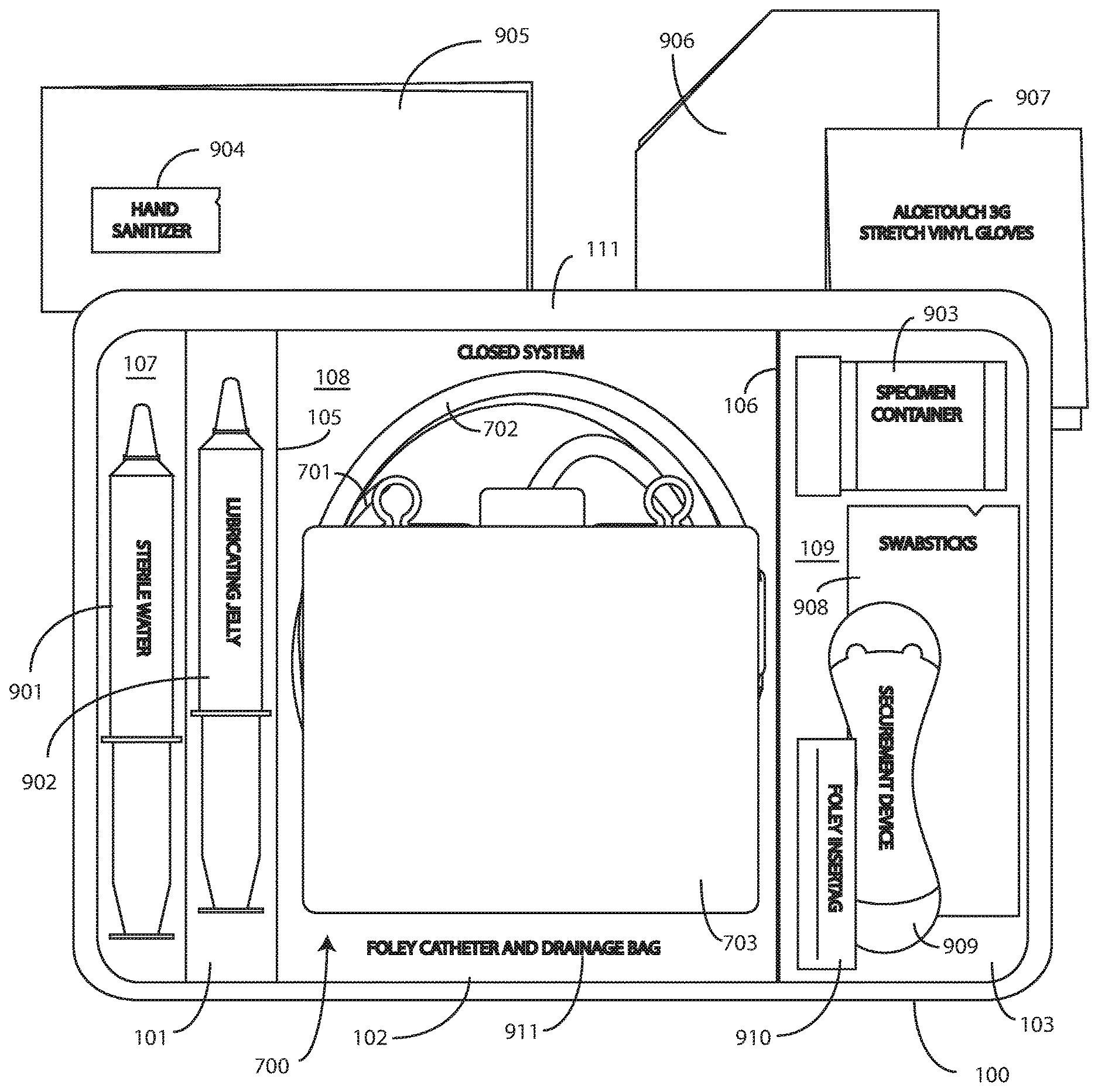
[0066] Turning now to FIG. 9, illustrated therein is illustrated therein is a single-layer tray 100 having the catheter assembly 700 of FIG. 8, syringes 901,902, and a specimen container 903 stored therein as a catheter packaging system in accordance with one or more embodiments of the disclosure. The illustrative catheter packaging system of FIG. 9 includes a single-layer tray 100 having a first compartment 101, a second compartment 102, and a third compartment 103.
[0067] In this illustrative embodiment, the first compartment 101 is configured to accommodate syringes 901,902. The second compartment 102 is configured to accommodate a coiled medical device, such as catheter assembly 700. The third compartment 103 is configured to accommodate the specimen container 903. The third compartment 103 can accommodate other materials as well, including skin sanitizers 904 and cleansing liquids, solutions, or gels. Additional devices corresponding to Foley catheter use, including towels 905, drapes 906, rubber gloves 907, one or more swab sticks 908, a Foley catheter securement device 909, a Foley catheter insertion tag 910, and a Foley insertion tag, which is a dated and/or time stamped label that is secured to the catheter tubing once the Foley catheter 701 is inserted, and so forth, can be disposed in the single-layer tray 100 as well. As an illustration of this flexibility, one or more towels can be disposed beneath the catheter assembly in one or more embodiments.
[0068] In this illustrative embodiment, the catheter assembly 700 is inverted in the second compartment. This means that the Foley catheter 708 is adjacent to the second compartment base member 108, with the coiled tubing 702 atop the Foley catheter 701, and the fluid drain bag 703 atop the coiled tubing 702. Said differently, the Foley catheter 701 is positioned between the second compartment base member 108 and the coiled tubing. Similarly, the coiled tubing 702 is positioned between the Foley catheter 701 and the fluid drain bag 703. Alternatively, where towels or other components are placed beneath the catheter assembly 700, the Foley catheter 701 can be positioned between those components and the coiled tubing 702.
[0069] In this illustrative embodiment, the both the Foley catheter 701 and the coiled tubing 702 are positioned between the second base member 108 and the fluid drain bag 703. In this illustrative embodiment, the Foley catheter 701 is positioned between the coiled tubing 702 and the second base member 108.
[0070] As noted above, this inverted positioning of the catheter assembly 700 in the second compartment 102 offers numerous advantages over prior art designs. First, having the fluid drain bag 703 as the outer-most component provides an additional protective layer for both the coiled tubing 702 and the Foley catheter 701. This additional protective layer helps to ensure that the coiled tubing 702 and the Foley catheter 701 remain sterile, even after the single-layer tray 100, with its open top, is opened.
[0071] Second, inverting the catheter assembly 700 allows the fluid drain bag 703 to be removed from the second compartment 102 first, and without disturbing the coiled tubing 702 and the Foley catheter 701. This provides more workspace within the single-layer tray 100 for a medical services provider. Third, removal of the fluid drain bag 703 first from the single-layer tray 100 allows it to be placed in a position that will help to increase the efficiency of fluid flow once the Foley catheter 701 is placed into a patient.
[0072] As also noted above, in one embodiment the flange 111 or other parts of the single-layer tray 100, e.g., the first compartment base member 107, the second compartment base member 108, or the third compartment base member, can include instructions 911 or other graphical indicia. In one or more embodiments, the implements disposed in the various compartments 101,102,103 can have implements therein arranged in accordance with use during a Foley catheterization procedure. In one embodiment, the instructions 911 can be coordinated with this arrangement, indicating that components disposed in the first compartment 101 should be used first, components disposed in the second compartment 102 should be used next, and so forth. To assist the user in understanding workflow, arrows or other directional elements can be included on the flange 111 or other parts of the single-layer tray 100 as well.
[0073] As illustrated in FIGS. 1-6, each compartment of the single-layer tray 100 includes a compartment base member. Further, each compartment is separated by a barrier having an opening therein. A first barrier 105, optionally having a first opening therein, separates the first compartment 101 from the second compartment 102. Similarly, a second barrier 106, also optionally having a second opening 122 therein separates, the second compartment 102 from the third compartment 103.
[0074] Syringes 901,902 are disposed in the first compartment 101. In one or more embodiments, one syringe 902 contains a sterile liquid, such as sterile water. In one or more embodiments, another syringe 901 contains a lubricant, such as lubricating jelly. The lubricating jelly can be discharged into the first compartment 101 to lubricate at least a portion of the Foley catheter 701 in one or more embodiments when the Foley catheter 701 is passed from the second compartment 102 into the first compartment 101.
[0075] In one or more embodiments, one syringe 901 is supported at a different elevation within the single-layer tray 100 than the other syringe 902. The different elevations can be relative to each syringe 901,902, or to other components of the single-layer tray 100, such as the second compartment base member 108. Said differently, in one or more embodiments one syringe 901 is supported by the first compartment base member 107 at a shallower depth within the single-layer tray 100 than the depth of the second compartment base member 108. Further, where the first compartment base member 107 is inclined relative to other base members, in one or more embodiments one or both syringes 901,902 can be supported in a non-parallel configuration relative to the second compartment base member 108.
[0076] As noted above, some medical procedures will call for more materials than can be accommodated by a syringe capable of fitting within the first compartment 101. For such procedures, the single-layer tray 100 can be packed with larger syringes. A large syringe (not shown) can be supported laterally within the single-layer tray 100 when it is placed across the single-layer tray 100 such that it lies within one or more of the first compartment 101, the second compartment 102, or the third compartment 103. For example, the larger syringe can be placed within an opening of the first barrier 105 and an opening of the second barrier 106 (where included). Such a syringe can pass across the top of the catheter assembly 700. In other embodiments, the syringe (where fitting) can simply be placed adjacent to the catheter assembly 700 in the second compartment 102.
[0077] Once the necessary components are disposed within the single-layer tray 100, the tray can be sealed with a wrap to keep the internal components sterile. The wrap can be any of a number of types of material. In one embodiment, the wrap comprises a Central Sterile Reprocessing (CSR) wrap that is used widely by medical professionals in hospitals, ambulatory surgical centers, and the like during medical procedures. While a CSR wrap is one example of a wrap that can be used, it will be clear to those of ordinary skill in the art that other wraps, such as plastic, cotton, linen, paper, or combinations thereof, can be substituted without departing from the spirit and scope of the disclosure.
[0078] Using a CSR wrap as an illustrative example, in one embodiment the CSR wrap is folded about the single-layer tray 100 for sealing, and can be correspondingly unfolded to reveal the single-layer tray 100. Once unfolded, the CSR wrap can then be used in the catheter insertion process. For example, an unfolded CSR wrap can be used to provide a sterile field in which the single-layer tray 100 sits for unloading and subsequent use.
[0079] Printed instructions can then be attached to, disposed upon, or disposed within the single-layer tray 100. In one embodiment, the printed instructions include a health care services portion and a patient portion. The health care services portion can include instructions telling the health care services provider, for example, how to set up a sterile or otherwise clean work environment, how to prepare the catheter assembly 700 disposed within the tray, how to use the other devices within the tray, how to insert the catheter, how to secure the drainage bag to the catheter, how to empty the drainage bag, how to obtain a urine sample, and so forth. The instructions can include pictures or illustrations showing visually how the various steps should be done as well.
[0080] The patient portion can include helpful suggestions or instructions for the patient. The patient portion can be detachably coupled to the health care services portion, such as by a perforated line that is easily torn to separate the patient portion from the health care services portion. Examples of suggestions or instructions that may be included in the patient portion include information on what a catheter is, what the patient should understand about the catheter, how to reduce the chance of getting an infection, information about infections commonly associated with catheters, symptoms of infections commonly associated with catheters, and suggestions for home use of the catheter assembly 700. In one embodiment, the health care services portion may include an instruction for the health care services provider to detach the patient portion from the health care services portion and instructions to discuss the patient portion with the patient.
[0081] The health care services portion can tell the medical services provider how to perform a standard catheterization procedure. For instance, in one embodiment, the single-layer tray 100 is equipped with an adhesive label that can be used to identify the patient or specimen in the specimen container 903. Further, a label can be included to mark or otherwise identify the material in the fluid bag attached to the catheter. Such labels can include pre-printed fields, such as date, time and name. Further the printed instructions can notify the medical services provider that the devices disposed within the single-layer tray 100 are ordered corresponding to use during the catheterization procedure.
[0082] In another embodiment, the printed instructions can inform the medical services provider of special instructions. For instance, in one embodiment the printed instructions can inform the medical services provider not to leave a catheter in a patient for more than forty-eight hours without a physician's approval. Where the printed instructions include such information, the labels included in the single-layer tray 100 may have pre-printed fields for the time of insertion that can be filled in by the medical services provider performing the catheterization procedure.
[0083] Once the printed instructions have been affixed to, or placed with, within, or atop the single-layer tray 100, the assembly can be sealed in a sterile wrap such as a thermally sealed bag. The thermally sealed bag can optionally include a preformed opening. For example, in one embodiment, the opening can include one or more tabs that a health care services provider is instructed to pull to open the bag. Inclusion of a sterile wrap not only keeps the contents within the bag sterile, but also allows the instructions to be included with the tray assembly, yet outside the CSR wrap.
[0084] In one embodiment the printed instructions are disposed atop the CSR wrap such that the health care services portion of the printed instructions is disposed on the top of the printed instructions, with the patient portion being disposed adjacent to the CSR wrap, such as when the printed instructions are configured as an accordion-style folded instruction pamphlet. While the printed instructions of one embodiment are configured as a folded, printed, separate article disposed atop the CSR wrap, it will be clear to those of ordinary skill in the art having the benefit of this disclosure that the disclosure is not so limited. For example, in one embodiment the sterile wrap can be optional. In one embodiment, rather than including separate printed instructions, the instructions for use can be printed on the CSR wrap as well.
[0085] Additional instruction materials may be included with the completed assembly as well. For example, in one embodiment an adhesive instruction tag can be affixed to the sterile wrap. In another embodiment the instruction tag may be adhered to an outer packaging, that encloses the tray, the sterile wrap material or both. For example, in one embodiment the instruction tag can include information regarding whether a catheter procedure is needed. Text such as "Is there a valid clinical reason?" may be included under an instruction to "Stop" that includes the following information: [0086] Before inserting the Foley catheter, at least one of the following conditions should exist: [0087] Acute urinary retention or obstruction [0088] Precise measurement of urinary output needed [0089] Select surgical procedures [0090] Open sacral or perineal wounds in incontinent patient [0091] Prolonged immobilization [0092] End of life care
[0093] Further, checklist text may be included, such as "Checklist for Foley Catheter Insertion" included under the word "Check" that includes the following information: [0094] Check Each Box Upon Completion: [0095] Obtain order from physician/provider [0096] Document clinical reason for insertion [0097] Explain procedure to patient [0098] Use smallest catheter possible [0099] Perform hand hygiene [0100] Follow aseptic technique
[0101] Additional information may also be included, such as a fillable form that provides fields for the date and time of insertion of the catheter to be recorded, the name of the health care services provider, and the signature of the health care services provider. The above text for the instruction tag is illustrative only, and may be customized as desired by the manufacturer.
[0102] Turning now to FIG. 10, illustrated therein is another single-layer tray 1000 configured in accordance with one or more embodiments of the disclosure. In this illustrative embodiment, the single-layer tray 1000 comprises a main compartment 1001, a syringe or catheter compartment 1002, a swab compartment 1003, a small storage or overflow compartment 1004, and a corner storage compartment 1005. In one or more embodiments, the single-layer tray 1000 also includes one or more stiffening ribs 1020. Where included, the stiffening ribs 1020 can help to strengthen the single-layer tray 1000, as well as preventing bending.
[0103] In the illustrative catheter packaging system of FIG. 10, the syringe or catheter compartment 1002 defines a first section of the single-layer tray 1000. In the illustrative catheter packaging system of FIG. 10, the main compartment 1001 defines a second section of the single-layer tray 1000. In the illustrative catheter packaging system of FIG. 10, the swab compartment 1003, small storage or overflow compartment 1004, and corner storage compartment 1005 collectively define a third section of the single-layer tray 1000.
[0104] In one or more embodiments, the swab compartment 1003 includes a well and one or more channels configured to respectively hold the one or more swabs therein. In one or more embodiments, the overflow compartment 1004 fluidly connects to the well through the one or more channels.
[0105] In one or more embodiments, sides 1008 and 1009 of the single-layer tray 1000 define orthogonal inner walls. These orthogonal inner walls bound the main compartment 1001. They can further define a corner of the main compartment 1001 at an intersection location. The main compartment 1001 can include interior fillets 1018 at each corner. The fillets 1018, where included, can somehow provide a reinforcing function.
[0106] Interior partitions 1010 and 1012 can separate the main compartment 1001 from other compartments. In one or more embodiments, the two interior partitions 1010 and 1012 are shorter in height than are the sides 1008,1009. The one or more partitions 1010,1012 can separate, for example, the first section of the single-layer tray 1000, the second section of the single-layer tray 1000, the third section of the single-layer tray 1000, and so forth.
[0107] Turning now to FIG. 11, illustrated therein is the single-layer tray 1000 from FIG. 10 having the catheter assembly 700 of FIG. 8, syringes 901,902, and a specimen container 903 stored therein as a catheter packaging system in accordance with one or more embodiments of the disclosure. In this illustrative embodiment, first section of the single-layer tray 1000 is configured to accommodate syringes 901,902. The second section of the single-layer tray 1000 is configured to accommodate a coiled medical device, such as catheter assembly 700. The third section of the single-layer tray 1000 is configured to accommodate the specimen container 903. The third section of the single-layer tray 1000 can accommodate other materials as well, such as one or more swab sticks 908.
[0108] In this illustrative embodiment, the catheter assembly 700 is inverted in the second section of the single-layer tray 1000. This means that the Foley catheter 708 is adjacent to the second compartment base member defining the base of the second section of the single-layer tray 1000, with the coiled tubing 702 atop the Foley catheter 701, and the fluid drain bag 703 atop the coiled tubing 702. Said differently, the Foley catheter 701 is positioned between the second compartment base member and the coiled tubing. Similarly, the coiled tubing 702 is positioned between the Foley catheter 701 and the fluid drain bag 703. Alternatively, where towels or other components are placed beneath the catheter assembly 700, the Foley catheter 701 can be positioned between those components and the coiled tubing 702.
[0109] In this illustrative embodiment, the both the Foley catheter 701 and the coiled tubing 702 are positioned between the second base member and the fluid drain bag 703. In this illustrative embodiment, the Foley catheter 701 is positioned between the coiled tubing 702 and the second base member.
[0110] As noted above, this inverted positioning of the catheter assembly 700 in the second compartment 102 offers numerous advantages over prior art designs. First, having the fluid drain bag 703 as the outer-most component provides an additional protective layer for both the coiled tubing 702 and the Foley catheter 701. This additional protective layer helps to ensure that the coiled tubing 702 and the Foley catheter 701 remain sterile, even after the single-layer tray 1000, with its open top, is opened.
[0111] Second, inverting the catheter assembly 700 allows the fluid drain bag 703 to be removed from the second compartment 102 first, and without disturbing the coiled tubing 702 and the Foley catheter 701. This provides more workspace within the single-layer tray 100 for a medical services provider. Third, removal of the fluid drain bag 703 first from the single-layer tray 1000 allows it to be placed in a position that will help to increase the efficiency of fluid flow once the Foley catheter 701 is placed into a patient.
[0112] Syringes 901,902 are disposed in the first section of the single-layer tray 1000. In one or more embodiments, one syringe 901 is supported at a different elevation within the single-layer tray 1000 than the other syringe 902. The different elevations can be relative to each syringe 901,902, or to other components of the single-layer tray 100, such as the second compartment base member. Said differently, in one or more embodiments one syringe 901 is supported in the first section of the single-layer tray 1000 at a shallower depth within the single-layer tray 1000 than second syringe 902.
[0113] Turning now to FIG. 12, illustrated therein is a method 1200 for manufacturing a packaged catheter assembly in accordance with embodiments of the disclosure. At step 1201, the manufacturer provides a single-layer tray having at least a first compartment for accommodating one or more syringes and a second compartment for accommodating a flexible medical device, such as a catheter assembly. As noted above, in one embodiment the first compartment will have a first compartment base member. The first compartment and second compartment can be separated by a first barrier, which can optionally have an opening therein.
[0114] Once the single-layer tray is procured, the manufacturer can dispose at least one syringe in the first compartment at step 1202. Optionally, at step 1203, the manufacturer may include additional components with the single-layer. For example, a catheter securement device, a Foley insert tag, or other complementary components may be included at this step 1203.
[0115] In one embodiment, as determined at decision 1205, a second syringe can be disposed in the first compartment at step 1206. In another embodiment, the second syringe will be disposed in the second compartment with the catheter assembly. In still another embodiment, the second syringe can be disposed laterally across one or more components.
[0116] At step 1204, the manufacturer will place the catheter assembly in the second compartment. In one or more embodiments, this step 1204 comprises inverting the catheter assembly prior to placement in the second compartment such that a coiled tubing of the catheter assembly, coupled between a Foley catheter and a fluid drain bag of the catheter assembly, is positioned or situated between the Foley catheter and the fluid drain bag. Accordingly, this results in the coiled tubing, the drain bag, and the Foley catheter being disposed within the compartment with the Foley catheter and the coiled tubing are positioned between the drain bag and the base member.
[0117] Other components may be disposed in the single-layer tray as well, including a specimen container that is disposed in a third compartment at step 1208. Further, other devices may be included, such as towels, drapes, printed instructions, one or more antiseptic packets, and so forth. These other devices can be disposed in various compartments within the single-layer tray.
[0118] At step 1209, the single-layer tray is sealed. This can be accomplished by folding a CSR wrap about the single-layer tray. In such an embodiment, the CSR wrap can be used during the catheter insertion procedure as well. At optional step 1210, the manufacturer can enclose printed instructions. In one embodiment, the printed instructions will direct a user to discharge contents of at least one syringe into the first compartment and to pass at least a portion of the catheter assembly through the opening and into the contents to lubricate the Foley catheter.
[0119] At step 1211, the manufacturer can place a sterile wrap about the tray and the printed instructions, where included. A sticker or other sealing device can be applied that indicates the contents to be sterile as well. At step 1212, the completed assembly can be shipped to a medical services provider.
[0120] Turning now to FIG. 13, illustrated therein are various embodiments of the disclosure. At 1301, a medical procedure kit comprises a single-layer tray comprising a first compartment at least partially bounded by a first base member and a second compartment at least partially bounded by a second base member. At 1301, the medical procedure kit comprises at least one syringe situated within the first compartment. At 1301, the medical procedure kit comprises a Foley catheter, coupled to coiled tubing and a fluid drain bag, and disposed within the second compartment. At 1301, the Foley catheter and the coiled tubing are positioned between the second base member and the fluid drain bag.
[0121] At 1302, the Foley catheter of 1301 is positioned between the coiled tubing and the second base member. At 1303, the first compartment and second compartment of 1302 each define open top compartments.
[0122] At 1304, the single-layer tray of 1303 comprises a perimeter wall. At 1304, the first compartment is at least partially bounded by the perimeter wall. At 1305, the single-layer tray of 1303 comprises a perimeter wall. At 1305, the second compartment is at least partially bounded by the perimeter wall.
[0123] At 1306, the at least one syringe of 1303 comprises a first syringe and a second syringe. At 1307, the first compartment of 1306 defines a lubricating jelly application chamber to lubricate at least a portion of the Foley catheter.
[0124] At 1308, the single-layer tray of 1303 further comprises a third compartment bounded by a third base member. At 1309, the medical procedure kit of 1308 further comprises a specimen jar. At 1309, the specimen jar is positioned within the third compartment. At 1310, the medical procedure kit of 1308 further comprises one or more swab sticks positioned within the third compartment.
[0125] At 1311, a medical procedure kit comprises a single-layer tray. At 1311, the single-layer tray comprises a first section, a second section, and a third section. At 1311, each of the first section, the second section, and the third section is bounded by a base member. At 1311, one or more partitions separate at least one of the first section, the second section, or the third section from another one of the first section, the second section, or the third section.
[0126] At 1311, a Foley catheter, coupled to coiled tubing and a fluid drain bag, is disposed within the first section. At 1311, the Foley catheter and the coiled tubing are positioned between the base member of the first section and the fluid drain bag.
[0127] At 1312, the Foley catheter of 1311 is positioned between the coiled tubing and the base member of the first section. At 1313, the medical procedure kit of 1311 further comprises a syringe. At 1313, the syringe comprises a lubricant. At 1313, the syringe comprising lubricant is positioned in the second section.
[0128] At 1314, one or more swabs are positioned within the third section of the single-layer tray of 1313. At 1315, the medical procedure kit of 1314 further comprises a specimen jar. At 1315, the specimen jar is positioned within the third section.
[0129] At 1316, the third section of the single-layer tray 1315 comprises a swab compartment. At 1316, the swab compartment includes a well and one or more channels configured to respectively hold the one or more swabs therein. At 1316, the third section of the single-layer tray 1315 comprises an overflow compartment fluidly connected to the well through the one or more channels. At 1316, the third section of the single-layer tray 1315 comprises a corner storage compartment. At 1317, the specimen jar of 1316 is positioned within the corner storage compartment.
[0130] At 1318, a medical procedure kit comprises a single-layer tray comprising a compartment bounded at its bottom by a base member and a lubricating jelly application chamber. At 1318, a container of lubricating jelly disposed within the single-layer tray. At 1318, coiled tubing is coupled between a Foley catheter and a drain bag. At 1318, the coiled tubing, the drain bag, and the Foley catheter are disposed within the compartment with the Foley catheter and the coiled tubing positioned between the drain bag and the base member.
[0131] At 1319, the lubricating jelly application chamber of 1318 is configured to lubricate at least a portion of the Foley catheter with the lubricating jelly. At 1320, the Foley catheter of 1319 is positioned between the coiled tubing and the base member.
[0132] The following applications are incorporated herein by reference for all purposes: Ser. No. 14/793,455, filed Jul. 7, 2015; Ser. No. 13/860,902, filed Apr. 11, 2013; Ser. No. 13/155,026, filed Jun. 7, 2011; Ser. No. 61/352,140, filed Jun. 7, 2010; Ser. No. 61/352,155, filed Jun. 7, 2010; Ser. No. 61/428,944, filed Dec. 31, 2010; Ser. No. 61/437,796, filed Jan. 31, 2011; Ser. No. 12/495,148, filed Jun. 30, 2009; Ser. No. 12/647,515, filed Dec. 27, 2009; Ser. No. 13/153,265, filed Jun. 3, 2011; and Ser. No. 13/153,300, filed Jun. 3, 2011.
[0133] In the foregoing specification, specific embodiments of the present disclosure have been described. However, one of ordinary skill in the art appreciates that various modifications and changes can be made without departing from the scope of the present disclosure as set forth in the claims below. Thus, while preferred embodiments of the disclosure have been illustrated and described, it is clear that the disclosure is not so limited. Numerous modifications, changes, variations, substitutions, and equivalents will occur to those skilled in the art without departing from the spirit and scope of the present disclosure as defined by the following claims. Accordingly, the specification and figures are to be regarded in an illustrative rather than a restrictive sense, and all such modifications are intended to be included within the scope of present disclosure. The benefits, advantages, solutions to problems, and any element(s) that may cause any benefit, advantage, or solution to occur or become more pronounced are not to be construed as a critical, required, or essential features or elements of any or all the claims.
* * * * *
D00000
D00001
D00002
D00003
D00004
D00005
D00006
D00007
D00008
D00009
D00010
D00011
XML
uspto.report is an independent third-party trademark research tool that is not affiliated, endorsed, or sponsored by the United States Patent and Trademark Office (USPTO) or any other governmental organization. The information provided by uspto.report is based on publicly available data at the time of writing and is intended for informational purposes only.
While we strive to provide accurate and up-to-date information, we do not guarantee the accuracy, completeness, reliability, or suitability of the information displayed on this site. The use of this site is at your own risk. Any reliance you place on such information is therefore strictly at your own risk.
All official trademark data, including owner information, should be verified by visiting the official USPTO website at www.uspto.gov. This site is not intended to replace professional legal advice and should not be used as a substitute for consulting with a legal professional who is knowledgeable about trademark law.