Cardiac Treatment System
Hjelle; Aaron J. ; et al.
U.S. patent application number 16/523607 was filed with the patent office on 2019-11-14 for cardiac treatment system. The applicant listed for this patent is Mardil Inc.. Invention is credited to James F. Buck, William E. Cohn, Aaron J. Hjelle, Karl R. Leinsing, Richard F. Schroeder.
| Application Number | 20190343636 16/523607 |
| Document ID | / |
| Family ID | 50475941 |
| Filed Date | 2019-11-14 |

| United States Patent Application | 20190343636 |
| Kind Code | A1 |
| Hjelle; Aaron J. ; et al. | November 14, 2019 |
CARDIAC TREATMENT SYSTEM
Abstract
A cardiac device for implantation proximate an exterior of a heart, the cardiac device including an inflatable bladder including an inner wall and an outer wall, wherein the inner wall itself is more expandable than the outer wall itself such that the inflatable bladder itself is configured to deform substantially inwardly to exert localized pressure against a region of the heart when the inflatable bladder is positioned adjacent the region of the heart and inflated.
| Inventors: | Hjelle; Aaron J.; (Andover, MN) ; Cohn; William E.; (Bellaire, TX) ; Schroeder; Richard F.; (Fridley, MN) ; Buck; James F.; (Independence, MN) ; Leinsing; Karl R.; (Dover, NH) | ||||||||||
| Applicant: |
|
||||||||||
|---|---|---|---|---|---|---|---|---|---|---|---|
| Family ID: | 50475941 | ||||||||||
| Appl. No.: | 16/523607 | ||||||||||
| Filed: | July 26, 2019 |
Related U.S. Patent Documents
| Application Number | Filing Date | Patent Number | ||
|---|---|---|---|---|
| 15218675 | Jul 25, 2016 | 10405981 | ||
| 16523607 | ||||
| 14053261 | Oct 14, 2013 | 9421101 | ||
| 15218675 | ||||
| 61713351 | Oct 12, 2012 | |||
| Current U.S. Class: | 1/1 |
| Current CPC Class: | A61F 2002/2484 20130101; A61F 2250/0003 20130101; A61F 2250/0098 20130101; A61M 1/107 20130101; D04B 21/12 20130101; A61M 1/122 20140204; A61F 2/9517 20200501; D10B 2509/08 20130101; A61B 2090/3966 20160201; A61M 2205/32 20130101; A61M 1/1008 20140204; A61M 1/12 20130101; A61M 1/106 20130101; A61F 2/2481 20130101; A61M 1/1068 20130101 |
| International Class: | A61F 2/24 20060101 A61F002/24; D04B 21/12 20060101 D04B021/12; A61M 1/10 20060101 A61M001/10 |
Claims
1. A cardiac device for implantation adjacent an exterior of a heart, the cardiac device comprising: an inflatable bladder comprising an inner wall and an outer wall, wherein the inner wall itself is more expandable than the outer wall itself such that the inflatable bladder itself is configured to deform substantially inwardly to exert localized pressure against a region of the heart when the inflatable bladder is positioned adjacent the region of the heart and inflated.
2. The cardiac device of claim 1, wherein the region of the heart comprises a mitral valve of the heart.
3. The cardiac device of claim 1, wherein: the inflatable bladder comprises a first inflatable bladder; the region comprises a first region; and the cardiac device further comprises a second inflatable bladder configured to exert localized pressure against a second region of the heart when the second inflatable bladder is positioned adjacent the second region of the heart and inflated.
4. The cardiac device of claim 3, wherein the second region comprises a papillary muscle of the heart.
5. The cardiac device of claim 3, further comprising a third inflatable bladder configured to exert localized pressure against a third region of the heart when the third inflatable bladder is positioned adjacent the third region of the heart and inflated.
6. The cardiac device of claim 5, wherein the third region of the heart comprises a tricuspid valve of the heart.
7. The cardiac device of claim 1, further comprising: a jacket configured for implantation circumferentially around ventricles of the heart, the jacket including an open top end configured to be positioned in an atrial-ventricular (A-V) groove of the heart, wherein the inflatable bladder is positioned adjacent the jacket.
8. The cardiac device of claim 7, wherein the inflatable bladder is located such that, when the top end of the jacket is in the A-V groove, the inflatable bladder is positionable adjacent to a mitral valve of the heart.
9. The cardiac device of claim 7, wherein the inflatable bladder is attached to the jacket.
10. The cardiac device of claim 1, further comprising a fluid supply line configured to be coupled to the inflatable bladder and provide fluid to the inflatable bladder.
11. The cardiac device of claim 1, wherein the inflatable bladder comprises silicon.
12. A method of providing localized pressure to one or more regions of a heart to improve heart functioning, the method comprising: a) positioning a cardiac device adjacent the heart, wherein the cardiac device comprises: an inflatable bladder comprising an inner wall and an outer wall, wherein the inner wall itself is more expandable than the outer wall itself such that the inflatable bladder itself is configured to deform substantially inwardly to exert localized pressure against a region of the heart when the inflatable bladder is positioned adjacent the region of the heart and inflated; and (b) inflating the inflatable bladder such that the inflatable bladder exerts localized pressure to the region of the heart.
13. The method of claim 12, wherein: the inflatable bladder comprises a first inflatable bladder; the region comprises a first region; and the method further comprises inflating a second inflatable bladder of the cardiac device to exert a localized pressure against a second region of the heart.
14. The method of claim 13, wherein: the first region comprises a mitral valve of the heart; the second region comprises a papillary muscle of the heart; and wherein inflating the first inflatable bladder reshapes the mitral valve and inflating the second inflatable bladder repositions the papillary muscle to relieve tension on chordae of the mitral valve.
15. The method of claim 14, further comprising inflating a third inflatable bladder of the cardiac device to exert a localized pressure on a third region of the heart.
16. The method of claim 15, wherein the third region comprises a tricuspid valve of the heart.
17. The method of claim 12, wherein said inflating the inflatable bladder occurs after fibrotic encapsulation.
18. The method of claim 12, wherein the cardiac device further comprises a jacket configured for implantation circumferentially around ventricles of the heart, the jacket including an open top end configured to be positioned in an atrial-ventricular (A-V) groove of the heart, wherein the inflatable bladder is positioned adjacent the jacket.
19. The method of claim 12, wherein inflating the inflatable bladder comprises filling the inflatable bladder with a fluid via a fluid supply line coupled to the inflatable bladder.
20. The method of claim 12, wherein inflating the inflatable bladder comprises filling the inflatable bladder with at least one of a group consisting of: air, inert gas, silicone gel, saline, and contrast agents.
Description
CROSS-REFERENCE TO RELATED APPLICATIONS
[0001] This application is a continuation of U.S. application Ser. No. 15/218,675 filed on Jul. 25, 2016, which claims priority to U.S. application Ser. No. 14/053,261 (now U.S. Pat. No. 9,421,101) filed on Oct. 14, 2013, which claims priority to U.S. Provisional Application Ser. No. 61/713,351 filed on Oct. 12, 2012. The contents of the aforementioned applications are hereby fully incorporated herein by reference.
TECHNICAL FIELD
[0002] The present disclosure relates to medical devices for treating heart diseases and valvular dysfunction, including valvular regurgitation.
BACKGROUND OF THE INVENTION
[0003] Various compression-style systems currently exist for treating heart diseases and conditions such as congestive heart disease and valvular dysfunction. These systems typically involve either: (a) jackets that are placed around the heart to limit heart expansion to treat congestive heart disease, or (b) bands that are placed around the heart with fillable chambers to exert localized pressure to re-form the shape of heart valves, for example to minimize valve leakage.
[0004] An example of the former is found in the Acorn Cardiovascular Inc. system set forth in U.S. Published Patent Application 2010/0160721 entitled "Cardiac Support Device With Differential Compliance." This device is used to treat congestive heart disease. Congestive heart disease is the progressive enlargement of the heart. This enlargement requires the heart to perform an increasing amount of work. In time, the heart cannot supply an adequate amount of blood, resulting in a patient that is fatigued and in discomfort. The Acorn Cardiovascular Inc. system is a cardiac support device that limits heart expansion using a flexible jacket positioned around the heart. In operation, the jacket surrounds the myocardium and provides reduced expansion of the heart during diastole. The jacket has upper and lower ends. The upper end is open. The lower end may be open or closed. The jacket is sized for the particular heart to be contained within its volume. When placed on the heart, the upper end of the jacket extends up to the valvular annulus and terminates along the AV groove. The jacket itself further extends down to constrain the lower ventricular extremities. In this position, the jacket provides sufficient constraint at the valvular annulus. Alternatively, the jacket may not cover the apex of the heart (but it will cover its left and right ventricles). This placement is desirable as it presents a constraint against enlargement of the ventricular walls of the heart. After the jacket is positioned on the heart, it can then be secured to the heart, for example, by suturing at various locations around its circumference. However, it is preferred to avoid excessive suturing locations as this would restrict contraction of the heart during systole. Once placed, the jacket's volume and shape can be adjusted by gathering together and suturing excess material. Specifically, the jacket is adjusted to be snug during diastole (without being too tight such that left ventricular pressure will rise). The jacket then constrains enlargement of the heart beyond this volume.
[0005] An example of the second type of system is found in Mardil, Inc.'s U.S. Pat. No. 8,092,363 entitled "Heart Band With Fillable Chambers To Modify Heart Valve Function." This device has a plurality of fillable chambers that exert inward radial forces on heart valves. These fillable chambers are disposed within the inner and outer layers of a silicone rubber band. In operation, this device is used to treat dilation of heart valves by applying localized pressure to the surface of the heart. For example, a pair of these fillable chambers positioned on either side of the mitral valve can be used to re-shape the mitral valve such that mitral valve leakage is minimized or stopped.
[0006] As can be seen, these two above systems operate quite differently on the patient's heart. The first (i.e.: Acorn) system stabilizes the base of the heart, but does not provide localized therapeutic pressure on the heart valves. The second (i.e. Mardil) system provides localized pressure to heart valves through all heart phases; however, it does not stabilize the base of the heart.
[0007] It would instead be desirable to provide a system that permits localized pressure on selected regions of the heart (similar to the Mardill '363 device), but avoids its use of a solid silicone rubber band wrapped around the heart that may interfere with contraction and dilation.
[0008] It would also be advantageous to provide a system that provides localized pressure on the heart and also offers the advantages of a knit mesh jacket. Advantages of a knit mesh could include the fact that it allows for more freedom in heart contraction and dilation. In addition, a mesh band will advantageously self-attach to the heart by way of fibrotic encapsulation. This would assist in positioning the inflatable bladder(s) at a desired location and preventing unwanted movement of the bladder(s) in the future.
SUMMARY
[0009] In preferred aspects, some embodiments described herein provide a mesh structure (which may be polyester) to position a bladder for deformation of the mitral valve or papillary muscle to decrease valvular regurgitation.
[0010] Particular embodiments of the present invention provide a system for providing localized pressure on regions of a patient's heart to treat various heart problems. In various applications, it can be used to apply pressure to the mitral valve to reshape the valve and prevent mitral regurgitation, or to the papillary muscle to prevent mitral regurgitation (by relieving tension on the chordae which prohibits proper valve function), or to the tricuspid valve to prevent regurgitation. With regard to the mitral valve, the anatomical target for deformation is the P2 area of the valve. By pressing on this spot, the distance across the valve is artificially reduced, thereby preventing the gap in the valve responsible for the regurgitation.
[0011] In preferred embodiments, the system comprises a jacket received around the heart, with one or more inflatable bladders positioned inside this jacket. The bladder(s) are differentially expandable such that they have an inner (heart-facing) surface that is more compliant than their outer (jacket-facing) surface. As a result, when the bladder(s) is inflated, its inner surface expands more than its outer surface (which may not expand at all). As such, the inflated bladder exerts an inward pressure on a localized region of the heart.
[0012] In one aspect, some embodiments described herein provide an assembly for providing localized pressure to a region of a patient's heart to improve heart functioning, comprising: (a) a jacket made of a flexible biocompatible material, the jacket having an open top end that is received around the heart and a bottom portion that is received around the apex of the heart; and (b) at least one inflatable bladder disposed on an interior surface of the jacket, the inflatable bladder having an inelastic outer (jacket facing) surface positioned adjacent to the jacket and an elastic inner (heart facing) surface such that inflation of the bladder causes the bladder to deform substantially inwardly to exert localized pressure against a region of the heart.
[0013] In another aspect, particular embodiments of the present invention provide a method of providing localized pressure to a region of a patient's heart to improve heart functioning, comprising: (a) positioning an assembly around a patient's heart, wherein the assembly comprises: a jacket and at least one inflatable bladder, wherein the jacket is made of a flexible biocompatible material having an open top end that is received around the heart and a bottom portion that is received around the apex of the heart, and the inflatable bladder is disposed on an interior surface of the jacket, the inflatable bladder having an inelastic outer surface positioned adjacent to the jacket and an elastic inner surface; and (b) inflating the bladder causing the bladder to expand such that the bladder deforms substantially inwardly to exert localized pressure against a region of the heart.
[0014] An important advantage of some embodiments of the system described herein not seen in existing systems is that its bladder(s) are differentially expandable, meaning that one side of the bladder expands more than the other when it is inflated. This provides very precisely targeted pressure to specific regions of the heart.
[0015] Another advantage of the some embodiments of the system described herein is that it uses a mesh jacket to support and position the inflatable bladder(s). An advantage of using a knit mesh (as opposed to a polymer band) to hold the bladder in position is that the mesh is self-attaching to the heart (i.e.: after fibrotic encapsulation). Moreover, there is an anticipated benefit for many patients as the mesh jacket can itself be used to treat the problem of congestive heart disease concurrently with bladder(s) treating valve leakage problems.
[0016] In preferred embodiments, the jacket has an elastic band with radiopaque markers at its open top end. With these features, the jacket can then be easily guided and placed at the heart's A-V groove. This makes it easy to position the inflatable bladder(s) at the desired locations on the patient's heart.
BRIEF DESCRIPTION OF THE DRAWINGS
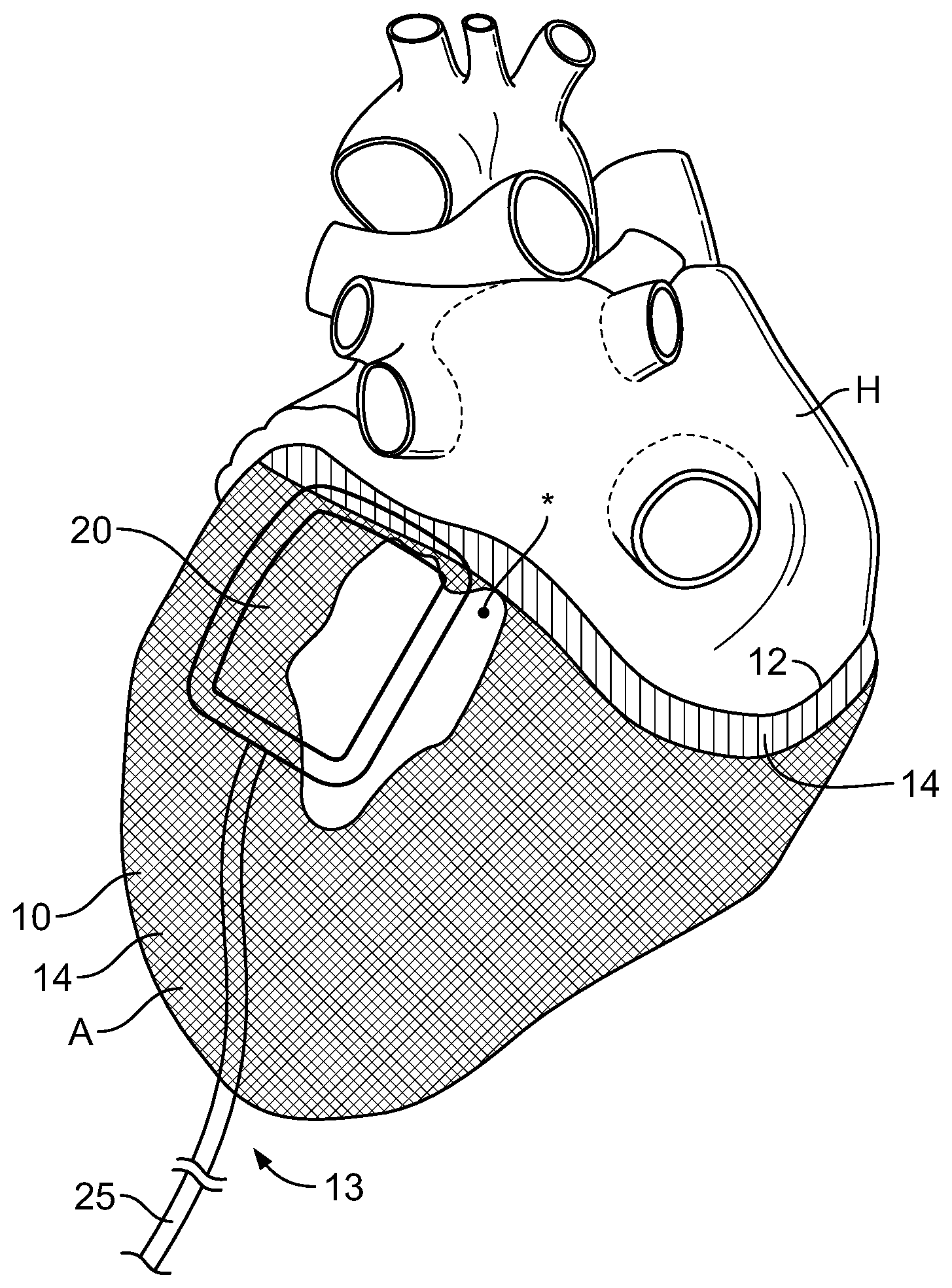
[0017] FIG. 1 A is a perspective view of the present assembly positioned on a patient's heart, showing an inflatable bladder positioned adjacent to the mitral valve.
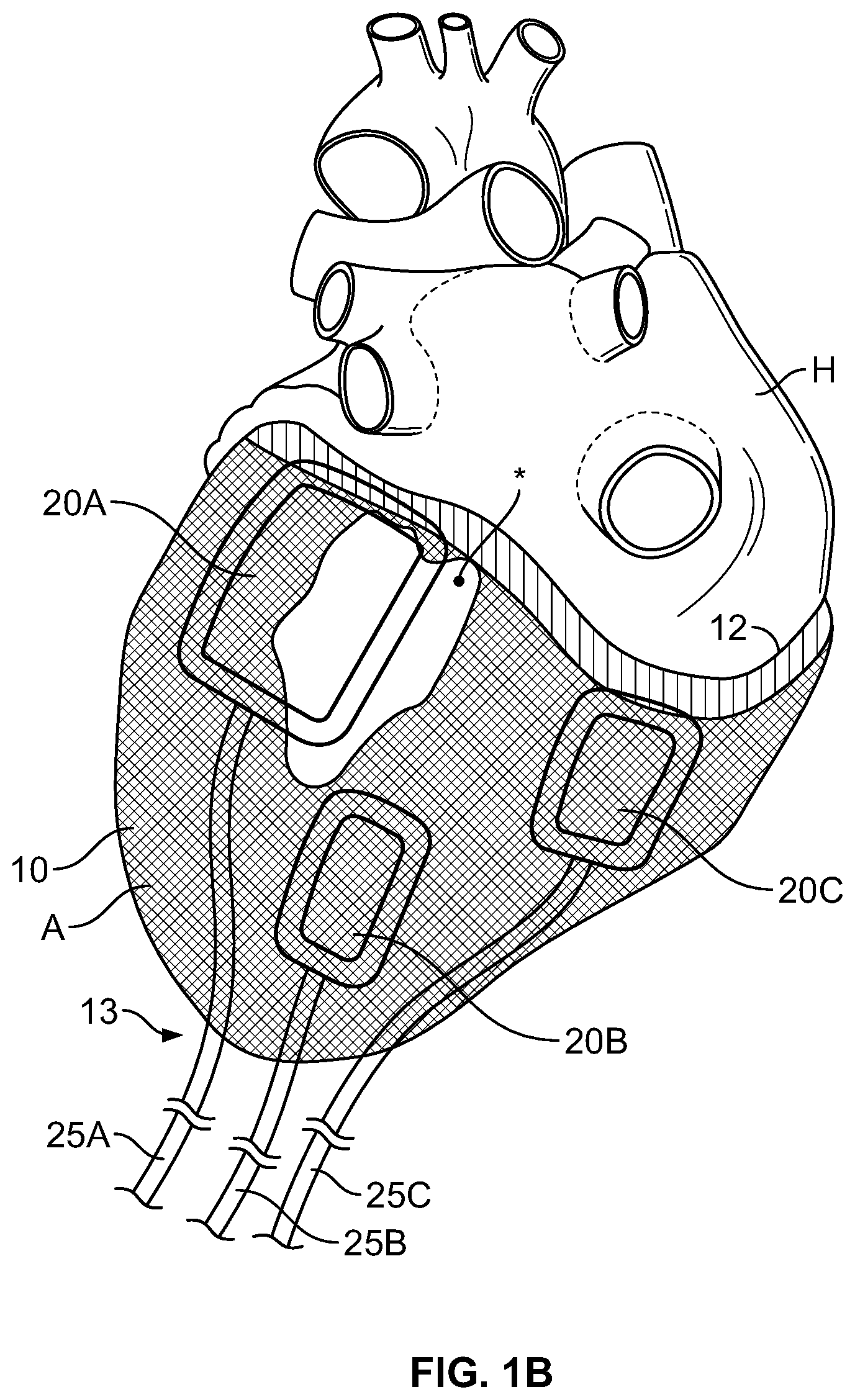
[0018] FIG. 1 B is a view similar to FIG. 1 A, but showing three optional bladder locations at the mitral valve, papillary muscle and tricuspid valve.
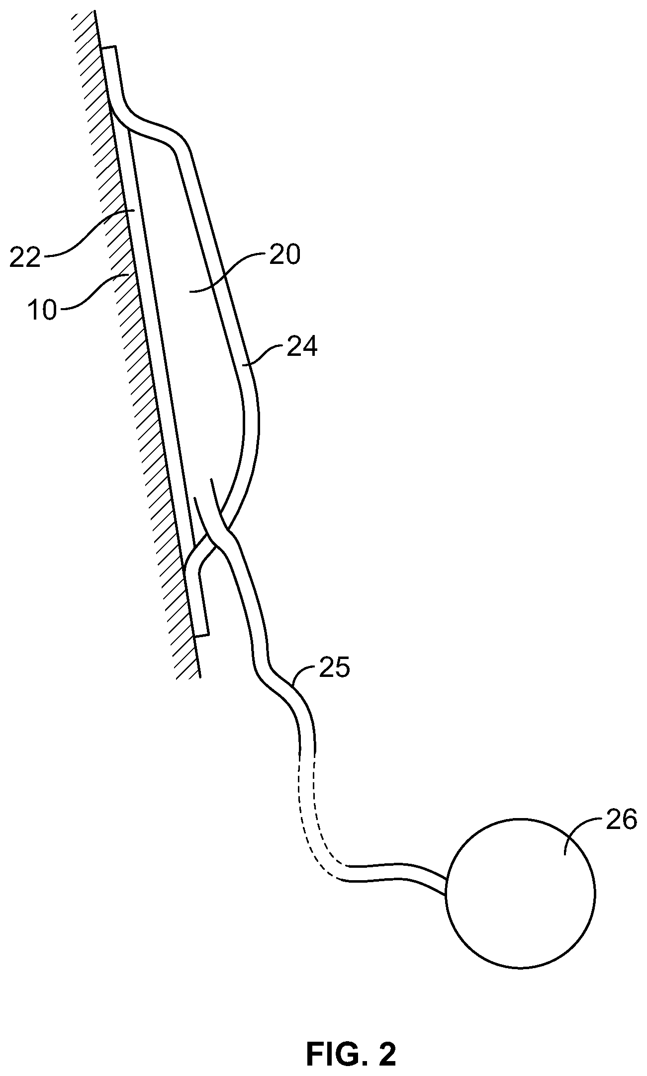
[0019] FIG. 2 is a sectional elevation view through one of the inflatable bladders.
DETAILED DESCRIPTION
[0020] Particular embodiments of the present invention provide an assembly for providing localized pressure to a region of a patient's heart. As will be described below, some embodiments described herein provide a jacket with one or more inflatable bladders received therein. Thus, the bladder(s) are positioned between the patient's heart and the jacket when the jacket is slipped over the heart.
[0021] FIGS. 1A and 1B show embodiments having one or more inflatable bladders, as follows. In FIG. 1A, the inflatable bladder is positioned adjacent to the patient's mitral valve. FIG. 1B shows additional placement locations of bladders adjacent to the papillary muscle and tricuspid valve. It is to be understood that the description herein encompasses embodiments with only one or with more than one inflatable bladder. Thus, FIGS. 1A and 1B simply show preferred locations for the bladder placement(s).
[0022] As seen in FIGS. 1A-B and 2, the depicted embodiment provides an assembly comprising: a jacket 10 and at least one inflatable bladder 20. Jacket 10 is made of a flexible biocompatible material and has an open top end 12 that is received around the heart H and a bottom portion 14 that is received around the apex A of the heart. In optional aspects, jacket 10 may be made of a knit mesh. This knit mesh may optionally be made of a polymer, including but not limited to high-density polyethylene. Alternatively, jacket 10 may be made of metal.
[0023] In one preferred embodiment, jacket 10 is made of a suitable knit material. An example of such a knit material may be the well known "Atlas Knit" material, being a knit structure formed from generally inelastic fibers. In an Atlas Knit, the fibers are interwoven into sets of parallel spaced-apart strands. In response to the low pressures of the heart during diastole, the fibers are generally non-elastic. Alternatively, jacket 10 may be elastic. Optionally, the fibers may be made of Denier polyester. However, other suitable materials, including but not limited to, PTFE, ePTFE, polypropylene and stainless steel may also be used. Advantages of using a knit material include flexibility, fluid permeability and minimizing the amount of heart surface area in direct contact with the jacket (thereby minimizing the potential of scar tissue development).
[0024] Inflatable bladder 20 is disposed on an interior surface of jacket 10. Bladder 20 may or may not be attached to jacket 10. FIG. 1B illustrates three separate inflatable bladders 20, being positioned at the mitral valve (bladder 20A), the papillary muscle (bladder 20B) and the tricuspid valve (bladder 20C). When bladder 20 is positioned adjacent to the mitral valve, it is preferably positioned at the P2 area of the valve (in the center of the posterior leaflet) to reduce the distance across the valve, thereby reducing the gap in the valve responsible for the regurgitation. When bladder 20 is positioned adjacent to the tricuspid valve, it performs a similar function, reducing regurgitation through the tricuspid valve. When bladder 20 is positioned adjacent to the papillary muscle, it gently corrects papillary muscle position and relieves tension on the chordae (which otherwise prohibits normal valve functioning).
[0025] As seen in FIG. 2, inflatable bladder 20 has an inelastic outer surface 22 positioned adjacent to jacket 10 and an elastic inner surface 24 positioned adjacent to the heart. Bladder 20 may optionally be made of silicon. In preferred aspects, jacket 10 is inelastic, the outer surface 22 of bladder 20 positioned adjacent to the bladder is inelastic and the inner surface 24 of bladder 10 is elastic. As a result, when inflated through fluid supply line 25, inflation of bladder 20 causes the bladder to deform substantially inwardly (i.e.: towards the heart). This then exerts localized pressure against a region of the heart. As can be seen, supply line(s) 25 are preferably positioned inside jacket 10 and extend out of an open bottom end 13 of the jacket adjacent to the apex of the heart. Bottom end 13 may be cinched closed after the jacket 10 has been positioned around the heart.
[0026] In preferred aspects, bladder 20 may be is inflated with fluids including air, inert gasses (such as fluorocarbons), silicone gel, saline and contrast agents. Supply lines 25 may optionally be inflated through a blunt needle port, a Luer port fitting, a subcutaneous port 26, etc. Supply lines 25 are made of a suitable bio-compatible material, including but not limited to silicone. The present invention preferably includes mechanisms for inflating and deflating bladders 20 post-implementation. For example, in one approach the device is first received onto the heart. After a period of time (e.g.: 30 days) fibrotic encapsulation of mesh jacket 10 will have occurred. At this time, the bladder(s) 20 can then be inflated (through supply line 25 using a needle to percutaneously access filling reservoir 26. Thus, subcutaneous ports 26 are useful for percutaneous inflation and deflation for therapy optimization or abandonment. Alternatively, the fluid path tube may stay in the intercostal space and be accessed by a small "cut-down" procedure to access the tube.
[0027] In optional embodiments, jacket 10 has an elastic band 14 passing around its top end 12. In addition, radiopaque markers 15 can also be provided around top end 12.
[0028] The present jacket and bladder system can be placed around the patient's heart in a variety of different approaches. In a preferred method of use, the present system further includes a delivery device for positioning the jacket onto the heart. Exemplary jacket designs and methods of placement are illustrated in US Published Patent Application 2010/0160721, incorporated herein by reference in its entirety. In one preferred aspect of the method, the assembly is implanted into the patient in a left intercostal mini-thoracotomy using contrast pericardiography and fluoroscopic visualization. After opening the parietal pericardium, the lower portion of the heart is free for applying the jacket over the apex. An example system for positioning the jacket is found in U.S. Pat. No. 5,702,343, incorporated herein by reference.
[0029] Particular embodiments described herein also include a preferred method of providing localized pressure to a region of a patient's heart H to improve heart functioning, by: (a) positioning an assembly around a patient's heart, wherein the assembly comprises: a jacket 10 and at least one inflatable bladder 20, wherein jacket 10 is made of a flexible biocompatible material having an open top end 12 that is received around the heart and a bottom portion 14 that is received around the apex of the heart, and the inflatable bladder 20 is disposed on an interior surface of the jacket, and the inflatable bladder 20 has an inelastic outer surface positioned adjacent to the jacket and an elastic inner surface. Next, bladder 20 is inflated causing it to expand such that the bladder deforms substantially inwardly to exert localized pressure against a region of the heart.
[0030] In another method of use, Pericardial Edge Management Strips (PEMS) are used. PEMS are sheets having one "peel and stick" side, and may be made of Teflon. These sheets can be used to keep the opening into the pericardium open to facilitate insertion of the device without damage to the pericardium (i.e.: the insertion tool getting hung up on the edges of the opening). In addition, Epicardial Management Strips (EMS) can be used to initially separate the heart from the mesh fabric. After the EMS are pulled out, the jacket fabric can then engage the heart.
[0031] An example of a suitable system for measuring the size of the heart is illustrated in International Patent Publication WO 2010/111592, entitled Intra-Operative Heart Size Measuring Tool. This device has a flexible measuring cord with length indicia that is placed around the heart. The distal end of the tool can be inserted through an opening in the patient's chest and pericardium and then positioned at a measurement position at the apex of the patient's heart. Circumference measurements can be made at the A-V groove or at other heart locations, as desired.
* * * * *
D00000
D00001
D00002
D00003
XML
uspto.report is an independent third-party trademark research tool that is not affiliated, endorsed, or sponsored by the United States Patent and Trademark Office (USPTO) or any other governmental organization. The information provided by uspto.report is based on publicly available data at the time of writing and is intended for informational purposes only.
While we strive to provide accurate and up-to-date information, we do not guarantee the accuracy, completeness, reliability, or suitability of the information displayed on this site. The use of this site is at your own risk. Any reliance you place on such information is therefore strictly at your own risk.
All official trademark data, including owner information, should be verified by visiting the official USPTO website at www.uspto.gov. This site is not intended to replace professional legal advice and should not be used as a substitute for consulting with a legal professional who is knowledgeable about trademark law.