Complex Sliding Desk System
OK; Cheor Sik ; et al.
U.S. patent application number 16/335156 was filed with the patent office on 2019-11-14 for complex sliding desk system. The applicant listed for this patent is Cheor Sik OK. Invention is credited to Se Hee CHO, Cheor Sik OK.
| Application Number | 20190343273 16/335156 |
| Document ID | / |
| Family ID | 60384930 |
| Filed Date | 2019-11-14 |


View All Diagrams
| United States Patent Application | 20190343273 |
| Kind Code | A1 |
| OK; Cheor Sik ; et al. | November 14, 2019 |
COMPLEX SLIDING DESK SYSTEM
Abstract
The present invention relates to a complex sliding desk system comprising a monitor supporting desk unit for supporting at least one monitor, wherein the monitor supporting desk unit comprises: a unit base; a column connected to the unit base; a desk plate disposed on an upper portion of the column; a monitor supporting part, disposed on the desk plate, for supporting the monitor; and a plate driving part, connected to the desk plate, for forward and rearward moving or rotating the desk plate.
| Inventors: | OK; Cheor Sik; (Yongin-si, KR) ; CHO; Se Hee; (Yongin-si, KR) | ||||||||||
| Applicant: |
|
||||||||||
|---|---|---|---|---|---|---|---|---|---|---|---|
| Family ID: | 60384930 | ||||||||||
| Appl. No.: | 16/335156 | ||||||||||
| Filed: | September 21, 2017 | ||||||||||
| PCT Filed: | September 21, 2017 | ||||||||||
| PCT NO: | PCT/KR2017/010410 | ||||||||||
| 371 Date: | March 20, 2019 |
| Current U.S. Class: | 1/1 |
| Current CPC Class: | A47C 1/022 20130101; A47B 2200/004 20130101; A47B 2083/025 20130101; A47B 39/023 20170801; A47B 2021/066 20130101; A47B 2200/0042 20130101; H02J 7/00 20130101; A47B 13/081 20130101; H04R 1/028 20130101; A47B 17/03 20130101; A47B 21/03 20130101 |
| International Class: | A47B 13/08 20060101 A47B013/08; A47B 17/03 20060101 A47B017/03 |
Foreign Application Data
| Date | Code | Application Number |
|---|---|---|
| Sep 21, 2016 | KR | 10-2016-0120743 |
Claims
1. A complex sliding desk system, comprising a monitor-supporting desk unit for supporting at least one monitor, wherein the monitor-supporting desk unit comprises: unit bases; columns respectively connected to the unit bases; a desk plate disposed on the column; a monitor supporting part, disposed on the desk plate, for supporting the monitor; and a plate driving part, connected to the desk plate, for moving forward and rearward or rotating the desk plate.
2. The complex sliding desk system according to claim 1, wherein the plate driving part comprises: a forward and reverse actuator for forward and rearward moving the desk plate with respect to a rail for supporting the desk plate; and a rotating actuator for rotating the desk plate, wherein a cut-out portion is formed on a front surface of the desk plate, and a non-slip part is provided on the desk plate.
3. The complex sliding desk system according to claim 1, wherein the monitor-supporting desk unit further comprises: a driving-part mounting part in which the plate driving part is mounted; and a speaker unit disposed at a rear of the desk plate.
4. The complex sliding desk system according to claim 1, wherein the monitor-supporting desk unit further comprises: a switch that is provided on one side of the desk plate and is used to input a signal to move forward and rearward or rotate the desk plate; and a switch panel that is provided on another side of the desk plate and comprises at least one of an earphone jack, a USB charging jack, and a data connection jack.
5. The complex sliding desk system according to claim 1, further comprising a chair unit that is disposed on one side of the monitor-supporting desk unit and has a backward-tilted structure allowing work in the most ideal posture on the waist of the human body such as a lying posture.
6. The complex sliding desk system according to claim 5, further comprising a rotary disc for rotatably supporting the chair unit.
7. The complex sliding desk system according to claim 5, further comprising a side table unit disposed on a side of the chair unit.
Description
TECHNICAL FIELD
[0001] The present invention relates to a complex sliding desk system, and more particularly, to a complex sliding desk system having a compact and simple structure, whereby manufacturing or purchasing costs may be reduced, thus increasing market penetration thereof, and convenience of use may be greatly improved, compared with conventional cases, because work may be performed in the most ideal posture on the waist of the human body, such as performing work in a lying posture.
BACKGROUND ART
[0002] Unlike the past, computers have recently been used to perform personal work or company work, or to play games in PC rooms.
[0003] In this respect, computers in modern society can be regarded as the closest electronic devices to people.
[0004] Accordingly, furniture companies are continuing to research and develop various types of desks, especially a desk system, in which a computer can be mounted, and various products are currently being marketed.
[0005] However, since computer-exclusive desks, or system furniture or desk systems corresponding thereto which are currently on the market have complicated structures, manufacturing or purchasing costs thereof are high, such that supply thereof is limited.
[0006] In particular, computer-exclusive desks, or system furniture or desk systems corresponding thereto which are currently on the market are not suitable for performing work in the most ideal posture on the waist of the human body, such as performing work in a lying posture. Considering the fact that conventional systems are not effective for people who perform work in a sitting position for long time, there is a need for a new concept of complex sliding desk system that is different from the conventional systems.
DISCLOSURE
Technical Problem
[0007] Therefore, the present invention has been made in view of the above problems, and it is one object of the present invention to provide a complex sliding desk system having a compact and simple structure, whereby manufacturing or purchasing costs may be reduced, thus increasing market penetration thereof, and convenience of use may be greatly improved, compared with conventional cases, because work may be performed in the most ideal posture on the waist of the human body, such as performing work in a lying posture.
Technical Solution
[0008] In accordance with an aspect of the present invention, the above and other objects can be accomplished by the provision of a complex sliding desk system including a monitor-supporting desk unit for supporting at least one monitor, wherein the monitor-supporting desk unit includes unit bases; columns respectively connected to the unit bases; a desk plate disposed on the column; a monitor supporting part, disposed on the desk plate, for supporting the monitor; and a plate driving part, connected to the desk plate, for moving forward and rearward or rotating the desk plate.
[0009] The plate driving part may include a forward and reverse actuator for forward and rearward moving the desk plate; and a rotating actuator for rotating the desk plate, with respect to a rail for supporting the desk plate, wherein a cut-out portion is formed on a front surface of the desk plate, and a non-slip part is provided on the desk plate.
[0010] The monitor-supporting desk unit may further include a driving-part mounting part in which the plate driving part is mounted; and a speaker unit disposed at a rear of the desk plate.
[0011] The monitor-supporting desk unit may further include a switch that is provided on one side of the desk plate and is used to input a signal to move forward and rearward or rotate the desk plate; and a switch panel that is provided on another side of the desk plate and includes at least one of an earphone jack, a USB charging jack, and a data connection jack.
[0012] The complex sliding desk system may further include a chair unit that is disposed on one side of the monitor-supporting desk unit and has a backward-tilted structure allowing work in the most ideal posture on the waist of the human body such as a lying posture.
[0013] The complex sliding desk system may further include a rotary disc for rotatably supporting the chair unit.
[0014] The complex sliding desk system may further include a side table unit disposed on a side of the chair unit.
Advantageous Effects
[0015] As apparent from the fore-going, the present invention advantageously provides a complex sliding desk system having a compact and simple structure. Accordingly, manufacturing or purchasing costs can be reduced, thus increasing market penetration thereof. Further, convenience of use can be greatly improved, compared with conventional cases, because work can be performed in the most ideal posture on the waist of the human body, such as performing work in a lying posture.
DESCRIPTION OF DRAWINGS
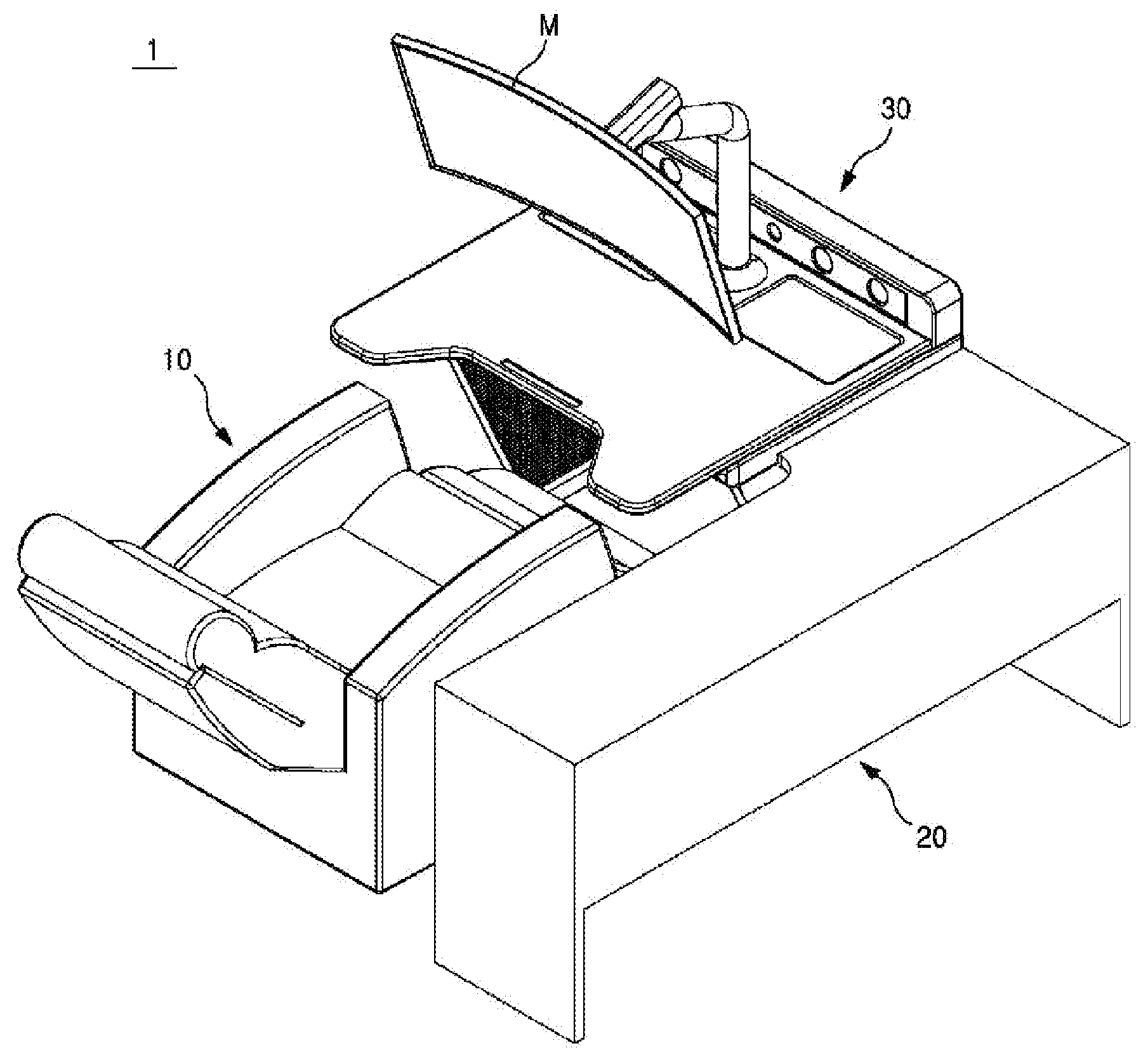
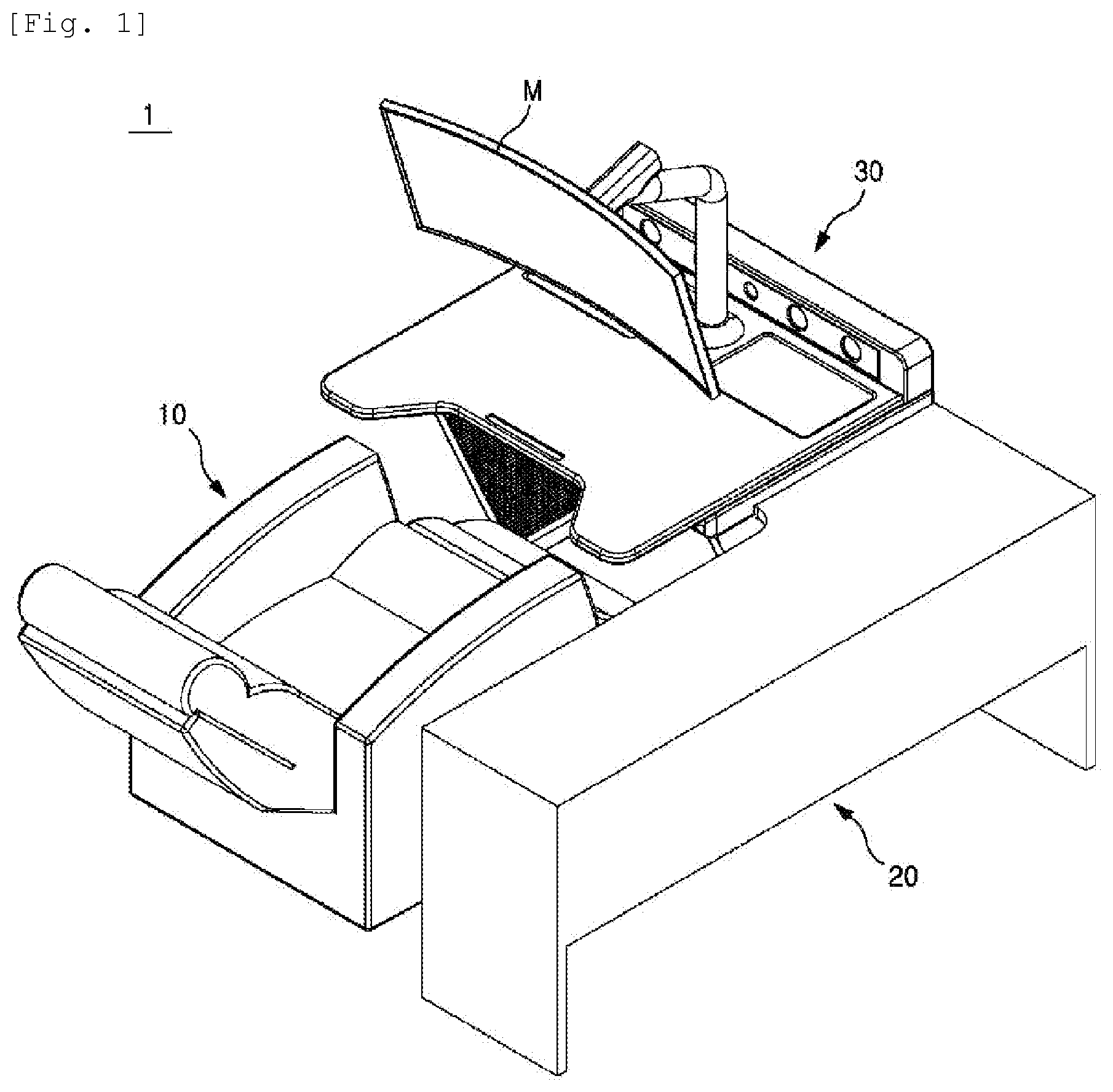
[0016] FIG. 1 illustrates a perspective view of a complex sliding desk system according to a first embodiment of the present invention.
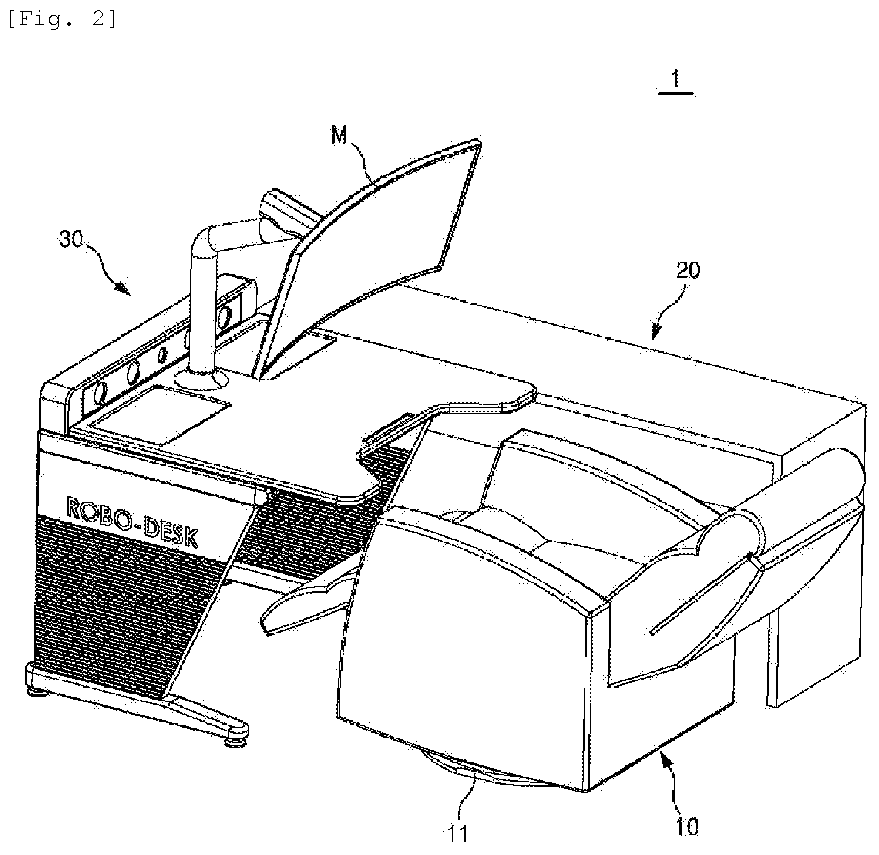
[0017] FIG. 2 illustrates a view of the complex sliding desk system of FIG. 1 taken at a different angle.
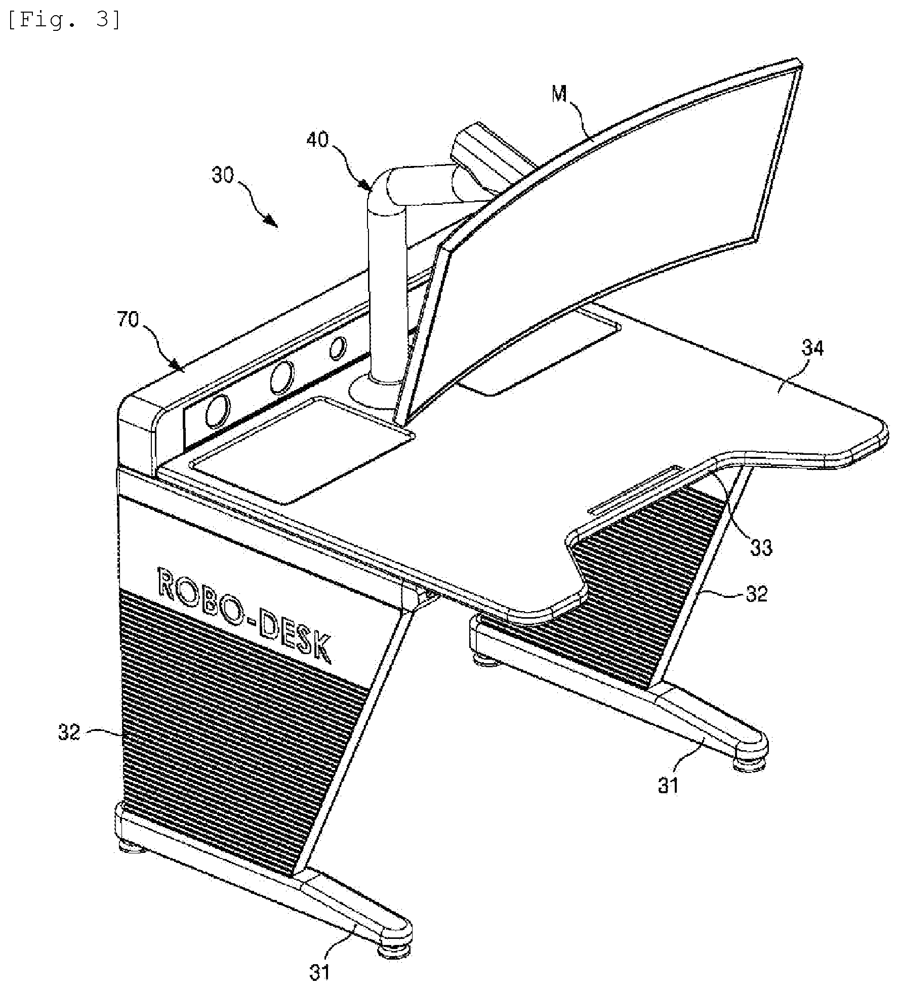
[0018] FIG. 3 illustrates a perspective view of a monitor-supporting desk unit.
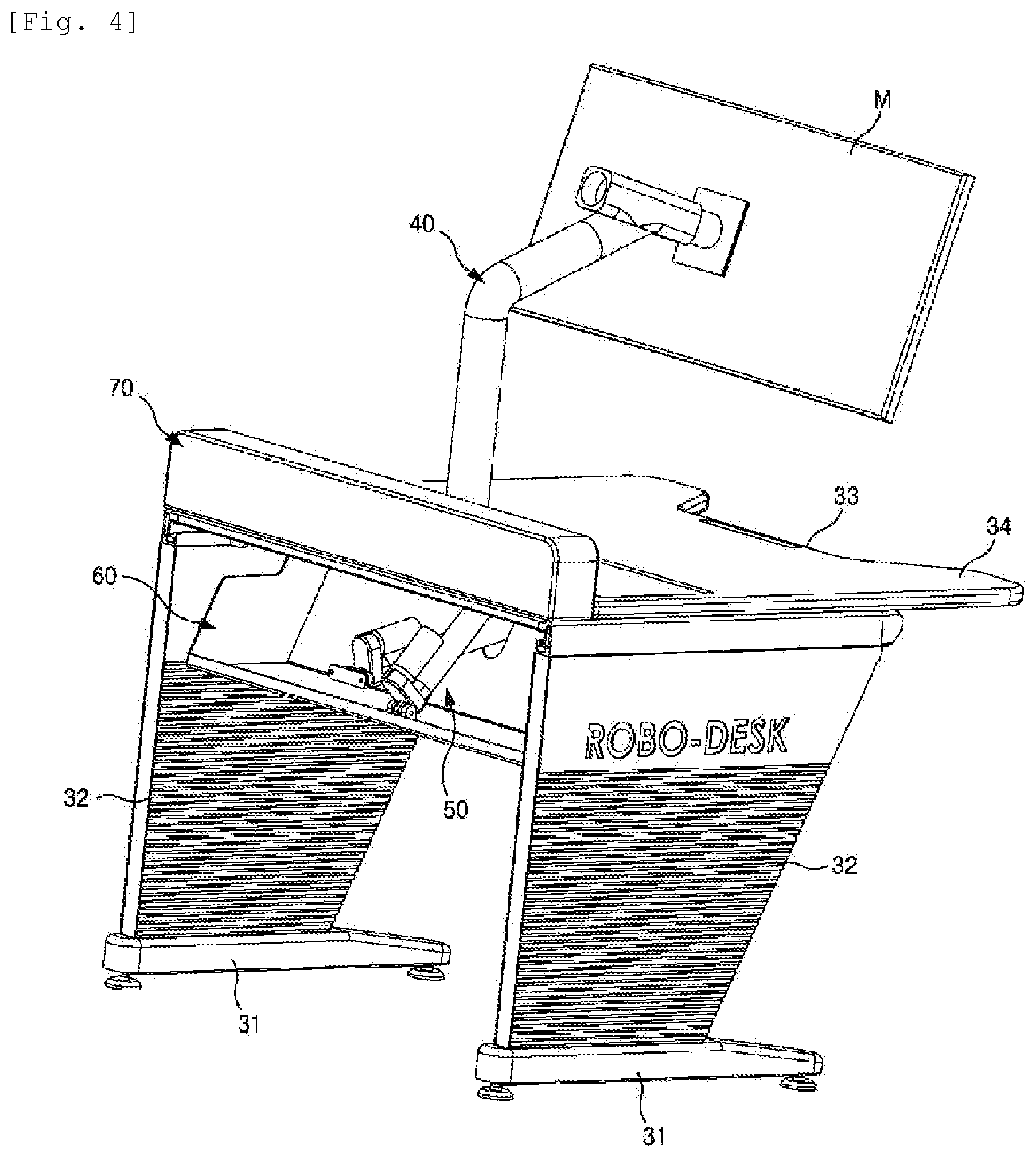
[0019] FIGS. 4 and 5 illustrate partially cutaway perspective views of the monitor-supporting desk unit of FIG. 3.
[0020] FIG. 6 illustrates a perspective view of a complex sliding desk system according to a second embodiment of the present invention.
[0021] FIGS. 7 and 8 illustrate views of the complex sliding desk system of FIG. 6 taken at different angles.
[0022] FIG. 9 illustrates a left side view of the complex sliding desk system of FIG. 6.
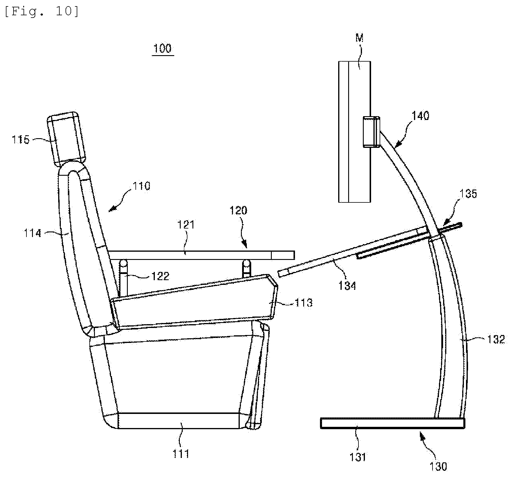
[0023] FIG. 10 illustrates a right side view of the complex sliding desk system of FIG. 6.
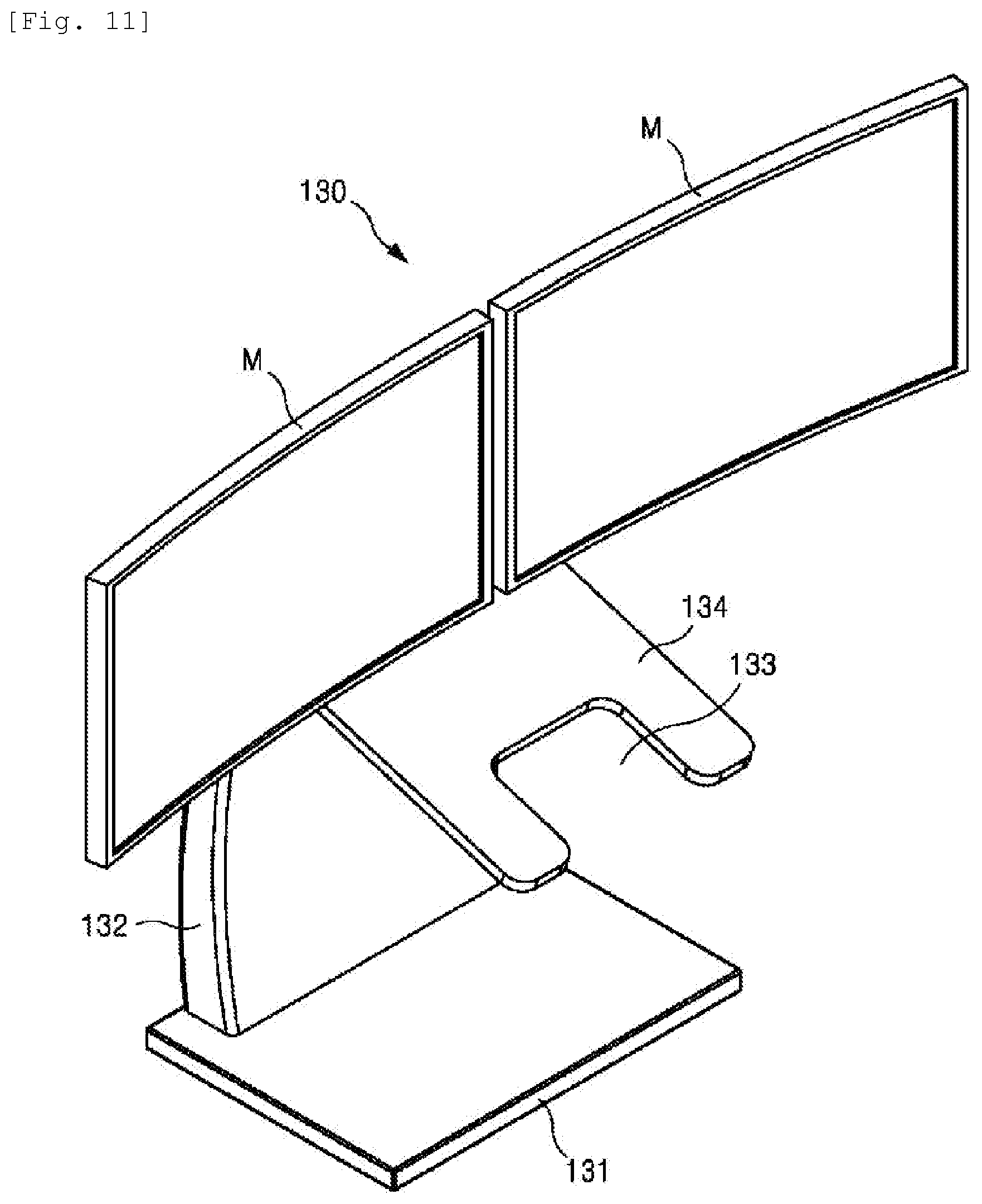
[0024] FIG. 11 illustrates an enlarged perspective view of a monitor-supporting desk unit.
[0025] FIG. 12 illustrates a rear perspective view of the monitor-supporting desk unit of FIG. 11.
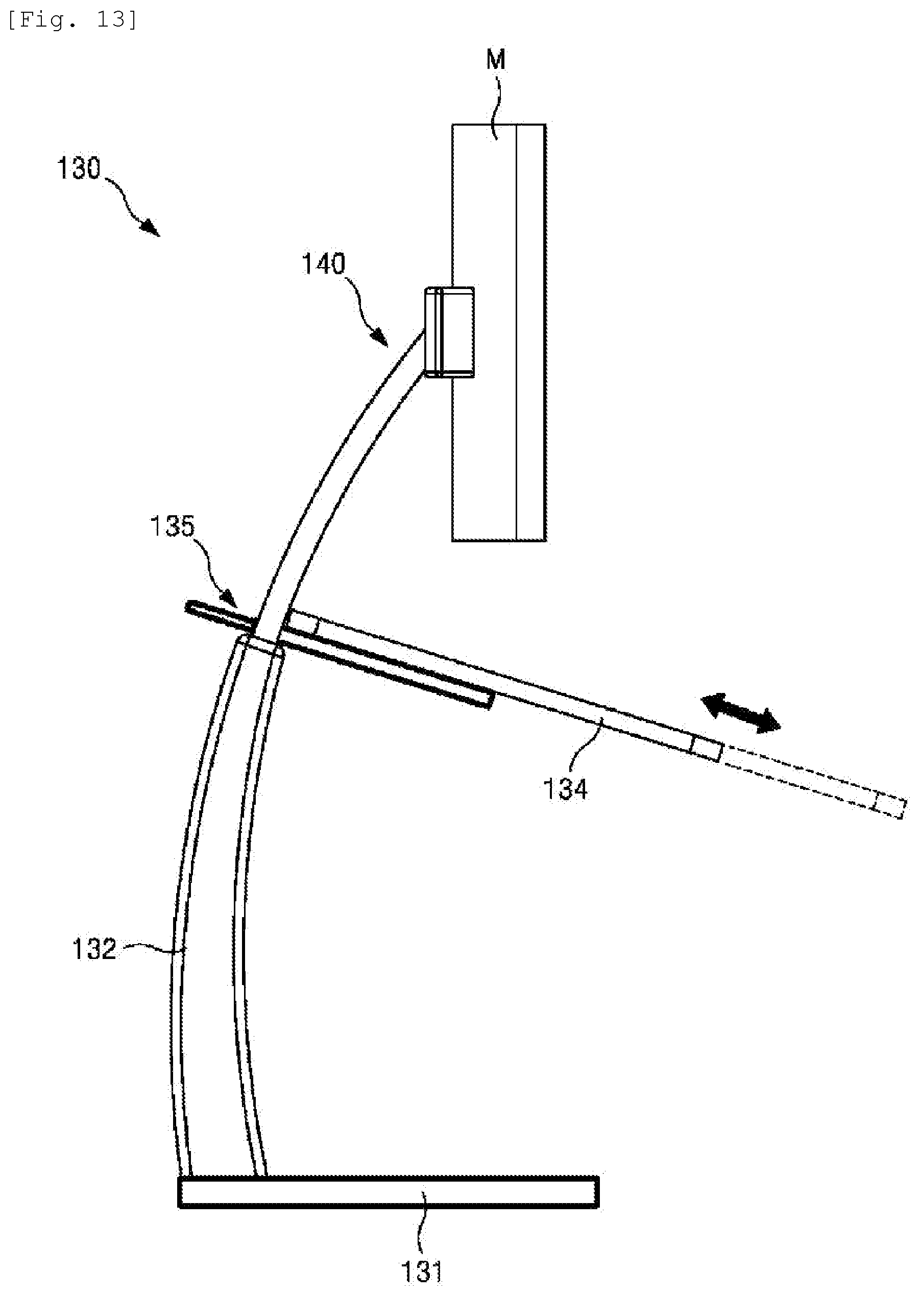
[0026] FIG. 13 illustrates a side view of the monitor-supporting desk unit of FIG. 11.
[0027] FIG. 14 illustrates a complex sliding desk system according to a third embodiment of the present invention.
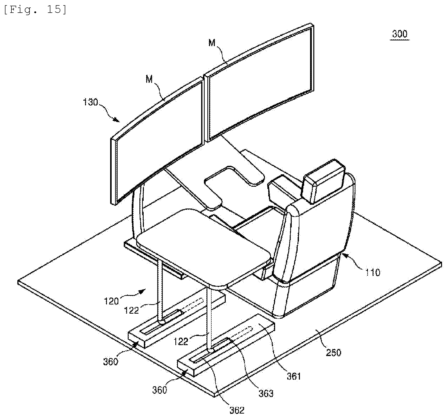
[0028] FIG. 15 illustrates a complex sliding desk system according to a fourth embodiment of the present invention.
[0029] FIG. 16 illustrates a monitor-supporting desk unit of a complex sliding desk system according to a fifth embodiment of the present invention.
[0030] FIG. 17 illustrates a complex sliding desk system according to a sixth embodiment of the present invention.
[0031] FIG. 18 illustrates an exploded view of the complex sliding desk system of FIG. 17.
[0032] FIG. 19 illustrates a complex sliding desk system according to a seventh embodiment of the present invention.
[0033] FIG. 20 illustrates a plan of a chair unit and a chair unit-supporting base of a complex sliding desk system according to an eighth embodiment of the present invention.
[0034] FIG. 21 illustrates a plan view of the chair unit-supporting base illustrated in FIG. 20.
[0035] FIG. 22 illustrates a perspective view of a complex sliding desk system according to a ninth embodiment of the present invention.
BEST MODE
[0036] Hereinafter, the attached drawings for illustrating exemplary embodiments of the present invention are referred to in order to gain a sufficient understanding of the present invention, the merits thereof, and the objectives accomplished by the implementation of the present invention.
[0037] The invention may, however, be embodied in many different forms and should not be construed as being limited to the embodiments set forth herein.
[0038] Rather, these embodiments are provided so that this disclosure will be thorough and complete, and will fully convey the concept of the invention to one of ordinary skill in the art. Meanwhile, the terminology used herein is for the purpose of describing particular embodiments and is not intended to limit the invention.
[0039] Accordingly, in certain embodiments, detailed descriptions of components, operations, and techniques well known in the art may be omitted to avoid obscuring appreciation of the present invention by a person of ordinary skill in the art.
[0040] Like reference numerals in the drawings denote like elements. The terminology used herein is for the purpose of describing particular embodiments only and is not intended to be limiting of the inventive concept.
[0041] The expression of singularity in the present specification includes the expression of plurality unless clearly specified otherwise in context. It will be further understood that the terms "comprise" or "provided with", when used in this specification, specify the presence of stated components and operations (actions), but do not preclude the presence or addition of one or more other components and operations.
[0042] Unless otherwise defined, all terms (including technical and scientific terms) used herein have the same meaning as commonly understood by one of ordinary skill in the art.
[0043] Also, it will be further understood that terms, such as those defined in commonly used dictionaries, will not be interpreted in an idealized or overly formal sense unless expressly so defined herein.
[0044] Hereinafter, the present invention will be described in detail by explaining exemplary embodiments of the invention with reference to the attached drawings.
[0045] FIG. 1 illustrates a perspective view of a complex sliding desk system according to a first embodiment of the present invention, FIG. 2 illustrates a view of the complex sliding desk system of FIG. 1 taken at a different angle, FIG. 3 illustrates a perspective view of a monitor-supporting desk unit, and FIGS. 4 and 5 illustrate partially cutaway perspective views of the monitor-supporting desk unit of FIG. 3.
[0046] Referring to the drawings, a complex sliding desk system 1 according to the first embodiment has a compact and simple structure. Accordingly, manufacturing or purchasing costs can be reduced, thus increasing market penetration thereof. Further, convenience of use can be greatly improved, compared with conventional cases, because work can be performed in the most ideal posture on the waist of the human body, such as performing work in a lying posture.
[0047] Accordingly, the complex sliding desk system 1 may prevent a neck disc or a back disc, thereby being effective for people who perform computer work or play games for a long time. Therefore, the complex sliding desk system 1 according to the first embodiment may be installed in Internet cafes, game rooms, and multipurpose complex spaces and may be used for various purposes such as personal business, company business, and design business.
[0048] The complex sliding desk system 1 configured to provide the aforementioned effects includes a chair unit 10, a side table unit 20, and a monitor-supporting desk unit 30 as illustrated in FIGS. 1 and 2.
[0049] Since the complex sliding desk system 1 including the chair unit 10, the side table unit 20, and the monitor-supporting desk unit 30, as in the embodiment, has a simple and compact structure, manufacturing or purchasing costs may be reduced, thereby increasing market penetration thereof. Among the components, the side table unit 20 and the like may be excluded.
[0050] The chair unit 10 is disposed on one side of the monitor-supporting desk unit 30. In the embodiment, the chair unit 10 has a backward-tilted structure allowing work in the most ideal posture on the waist of the human body such as a lying posture.
[0051] A rotary disc 11 is provided under the chair unit 10. The chair unit 10 may be rotated by the rotary disc 11. Accordingly, the chair unit 10 may face the monitor-supporting desk unit 30 or the side table unit 20. Therefore, convenience of use may be greatly improved.
[0052] The side table unit 20 is disposed on a side of the chair unit 10. Unlike the monitor-supporting desk unit 30 for supporting a monitor (M), the side table unit 20 may be utilized as a place for handwriting and as a place for placing simple articles, such as a mobile phone and a cup, thereon.
[0053] The side table unit 20 has a structure that is easy to move. Wheels may be provided under the side table unit 20.
[0054] Meanwhile, the monitor-supporting desk unit 30 may support the monitor (M). Although one monitor (M) is illustrated in the drawing, a dual monitor may be applied.
[0055] The monitor-supporting desk unit 30 may include unit bases 31, columns 32 respectively connected to the unit bases 31, a desk plate 34 disposed on the column 32, a monitor supporting part 40 disposed on the desk plate 34 and serving to support the monitor (M), and a plate driving part 50 connected to the desk plate 34 and serving to move forward and rearward or rotate the desk plate 34, as particularly illustrated in FIGS. 3 to 5.
[0056] The desk plate 34 serves to support a keyboard, a mouse, and the like. For convenience, a cut-out portion 33 may be formed on a front surface of the desk plate 34.
[0057] The monitor supporting part 40, which serves to support the monitor (M), may rotatably support the monitor (M) in addition to simply support the monitor (M). Such a structure is described in the following embodiments.
[0058] The plate driving part 50 may be mounted in a driving-part mounting part 60 provided in a box shape under the desk plate 34. Although the driving-part mounting part 60 is illustrated as being open for convenience in FIG. 4, the driving-part mounting part 60 is blocked by a wall. Accordingly, the driving-part mounting part 60 is not visible from the outside.
[0059] A speaker unit 70 may be provided at the rear of the desk plate 34. Accordingly, a complete computer system may be configured without connection of a separate speaker.
[0060] Although not shown in the drawings, the monitor-supporting desk unit 30 may further include a switch and a switch panel. The switch is provided on one side of the desk plate 34, particularly on one side of the front of the desk plate 34, and is used to input a signal to move forward and rearward or rotate the desk plate 34. Separate switches may be used to separately perform a forward and rearward moving operation and a rotation operation. The switch panel may be provided on another side of the desk plate 34 and may include at least one of an earphone jack, a USB charging jack, and a data connection jack. When the switch panel is provided, convenience of use may increase. In particular, when the switch panel is directly connected to the desk plate 34, the switch panel may be moved together with the movement of the desk plate 34, whereby convenience of use may be greatly improved.
[0061] Meanwhile, the plate driving part 50 includes a forward and reverse actuator 52 for moving (L) the desk plate 34 forward and rearward and a rotating actuator 53 for rotating (R) the desk plate 34 with respect to a rail 51 for supporting the desk plate 34, as particularly illustrated in FIG. 5. Both the forward and reverse actuator 52 and the rotating actuator 53 may be electric motors or pneumatic or hydraulic cylinders.
[0062] When the desk plate 34 is rotated in an R direction in FIG. 5 by operation of the rotating actuator 53, a keyboard or a mouse placed on the desk plate 34 may fall off. To prevent this, a non-slip part (not shown) may be provided on the desk plate 34. The non-slip part may be made of a special material having frictional force or may be a magnet.
[0063] Since the complex sliding desk system having the aforementioned structure and functions is simple and compact, manufacturing or purchasing costs may be reduced, thereby increasing market penetration thereof. Further, convenience of use may be greatly improved, compared with conventional cases, because work may be performed in the most ideal posture on the waist of the human body, such as performing work in a lying posture.
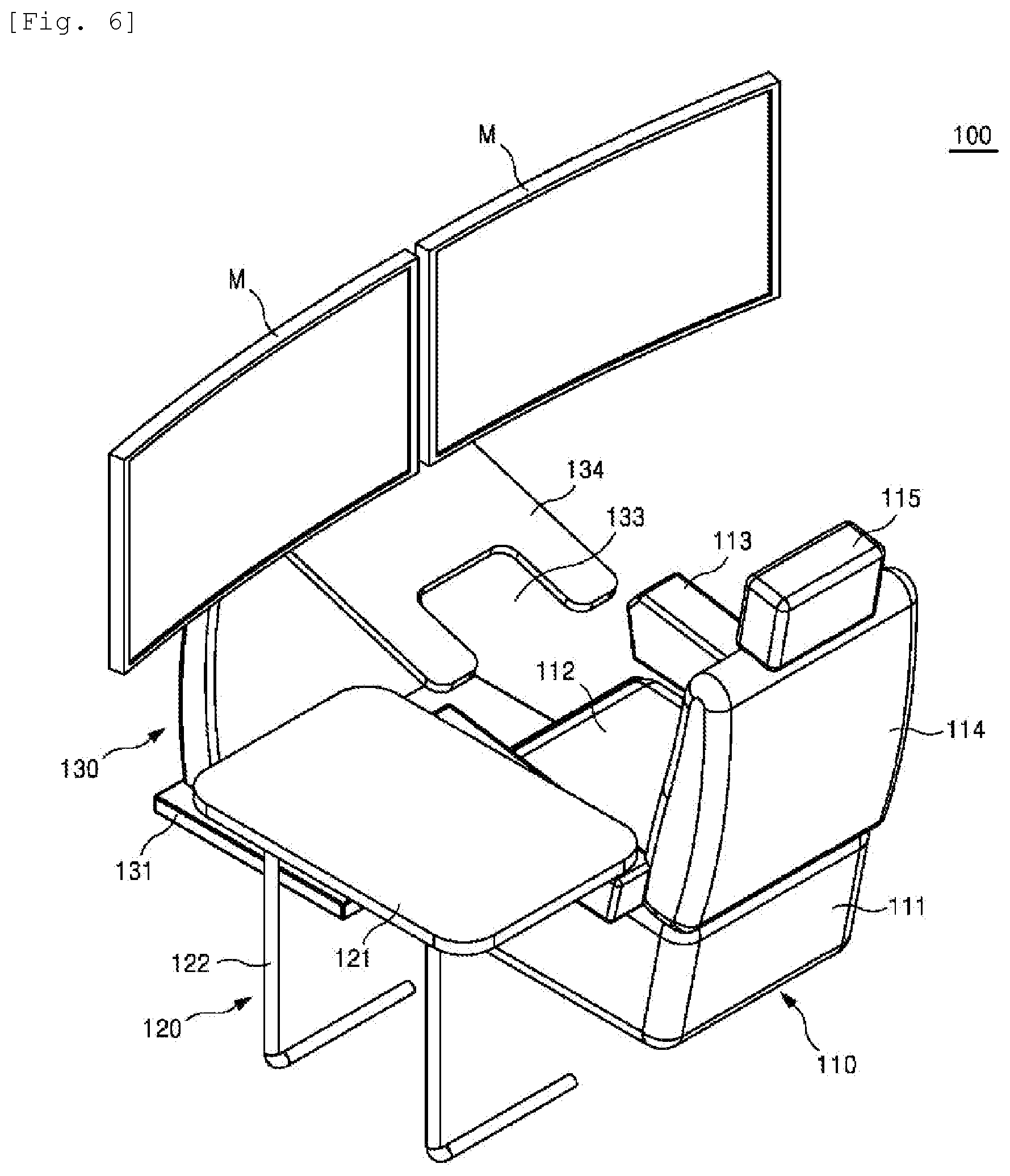
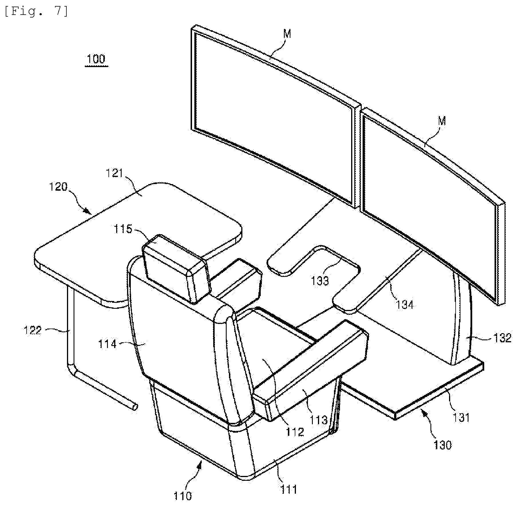
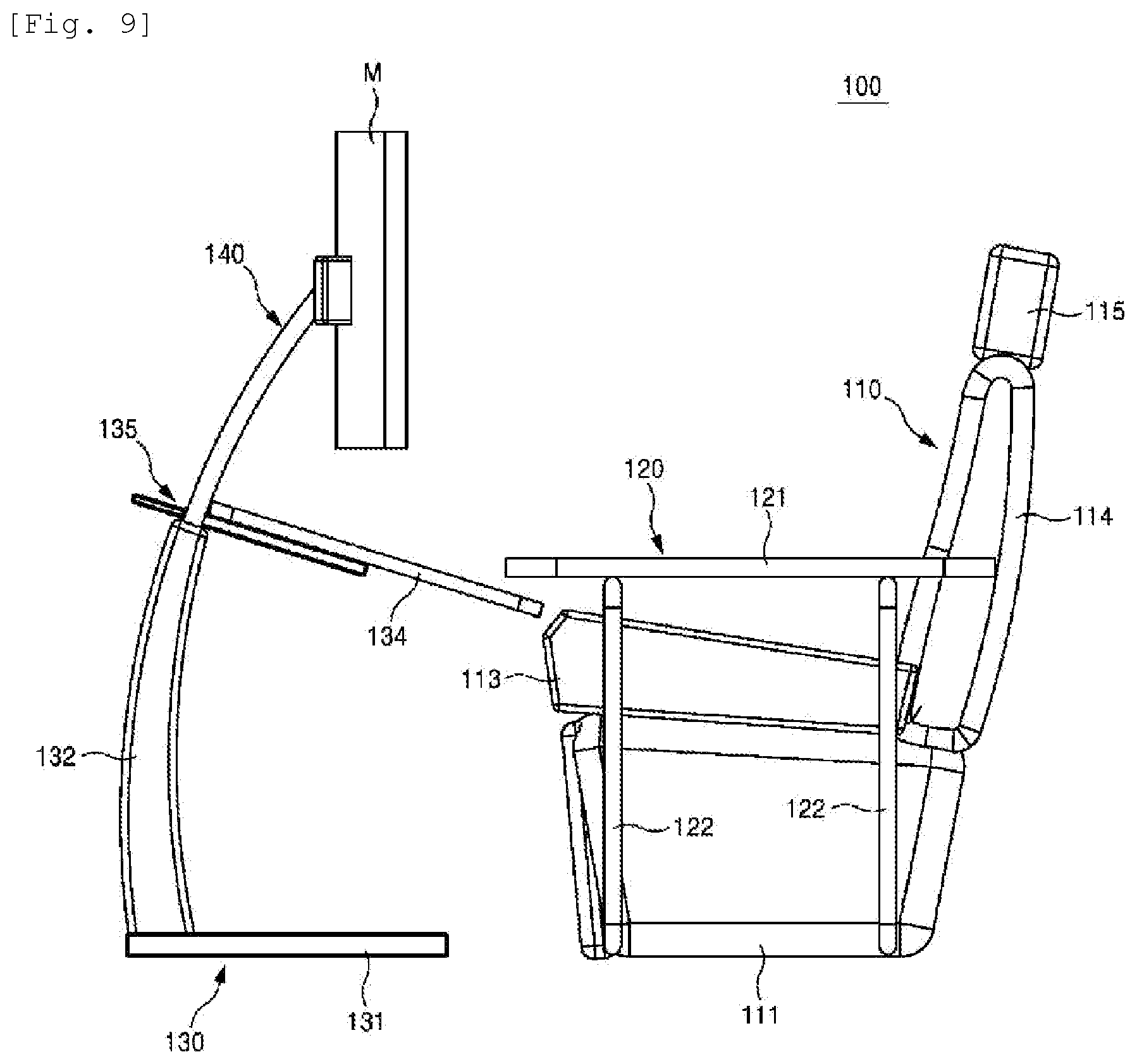
[0064] FIG. 6 illustrates a perspective view of a complex sliding desk system according to a second embodiment of the present invention, FIGS. 7 and 8 illustrate views of the complex sliding desk system of FIG. 6 taken at different angles, FIG. 9 illustrates a left side view of the complex sliding desk system of FIG. 6, FIG. 10 illustrates a right side view of the complex sliding desk system of FIG. 6, FIG. 11 illustrates an enlarged perspective view of a monitor-supporting desk unit, FIG. 12 illustrates a rear perspective view of the monitor-supporting desk unit of FIG. 11, and FIG. 13 illustrates a side view of the monitor-supporting desk unit of FIG. 11.
[0065] Referring to the drawings, a complex sliding desk system 100 according to the second embodiment of the present invention includes a chair unit 110 having a backward-tilted structure allowing work in the most ideal posture on the waist of the human body such as a lying posture, a side table unit 120 disposed on a side of the chair unit 110, and a monitor-supporting desk unit 130 disposed in front of the chair unit 110, serving to support a monitor (M), and being movable to change the position of the monitor (M) to a position corresponding to the chair unit 110.
[0066] The arrangement of the chair unit 110, the side table unit 120, and the monitor-supporting desk unit 130 illustrated in FIGS. 6 to 8 may be an optimized structure.
[0067] Examining the respective components, first, the chair unit 110 may be a general chair, particularly a recliner-like sofa with a cushion. In this case, it is possible to comfortably sit for a long time.
[0068] The chair unit 110 may include a supporter 111 supported by the ground surface, a seat 112 disposed on the supporter 111, a pair of armrests 113 disposed on both sides of the seat 112, a backrest 114 for supporting the back of a user, and a headrest 115 for supporting the head of a user. In particular, the seat 112 preferably has cushioning.
[0069] Although the chair unit 110 is shown in a standing state for convenience in FIGS. 6 to 8, the chair unit 110 preferably has a structure that is capable of being freely tilted backward, as illustrated in FIG. 22. In this case, a user may perform work (including studying) in a laying posture on the chair unit 110. As such, convenience of use may be greatly improved, compared with conventional cases, because work may be performed in the most ideal posture on the waist of the human body, such as performing work in a lying posture.
[0070] Next, the side table unit 120 is a table disposed on a side of the chair unit 110.
[0071] The side table unit 120 may include the side table plate 121; and a plurality of bent bridges 122 which support the side table plate 121 and one side of each of which is bent.
[0072] The side table plate 121 may be utilized upon performance of document work or to place documents or other stationery thereon.
[0073] In addition, the bent bridges 122 support the side table plate 121. Since an end of each of the bent bridges 122 has a bent shape, interference of the bent bridges 122 may be prevented even when the side table plate 121 approaches a user.
[0074] Finally, the monitor-supporting desk unit 130 is disposed in front of the chair unit 110 and serves to support a dual monitor (M).
[0075] Although a dual monitor (M) is illustrated and described in the embodiment, one monitor or three or more monitors may be applied. Therefore, the scope of the present invention is not limited as to the number of monitors (M).
[0076] The monitor-supporting desk unit 130 may include a unit base 131, a column 132, a desk plate 134, and a monitor supporting part 140. In particularly, the monitor-supporting desk unit 130 movably supports a dual monitor (M) such that the dual monitor (M) is disposed according to a position of a user when the chair unit 110 is tilted backward and thus the user lies down as illustrated in FIG. 22.
[0077] The unit base 131 is disposed at the bottom of the monitor-supporting desk unit 130. The column 132, the desk plate 134, and the monitor supporting part 140 are stably supported by the ground through the unit base 131.
[0078] The column 132 is disposed in an arc shape on one side of an upper part of the unit base 131. The dual monitor (M) may approach a user due to the column 132.
[0079] The desk plate 134, which is connected to the column 132, may be utilized upon performance of document work or to place documents thereon, other stationery, a keyboard, and the like, as in the side table plate 121 of the side table unit 120. In particular, when a keyboard is mounted thereon, the desk plate 134 may move forward to be located in front of a lying user, and thus a keyboard work may be sufficiently performed even when the user lies down.
[0080] A cut-out portion 133 is formed at the desk plate 134. The cut-out portion 133 may be provided for weight reduction or for arrangement of a keyboard, a mouse, and the like.
[0081] As indicated by an arrow in FIG. 13, a plate driving part 135 is connected to the desk plate 134 such that the desk plate 134 can move forward and backward. That is, the plate driving part 135 is respectively connected to the column 132 and the desk plate 134, and serves to move the desk plate 134 forward and backward with respect to the column 132.
[0082] The plate driving part 135 may have a telescoping bar structure such as an antenna structure. The plate driving part 135 may be implemented in an LM guide form or, in some cases, in a motorized structure with a motor and a ball screw or in a motorized structure combined with a slide rail structure.
[0083] The monitor supporting part 140 serves to substantially support the dual monitor (M). That is, one side of the monitor supporting part 140 is connected to the column 132, and another side thereof supports the dual monitor (M).
[0084] The monitor-supporting desk unit 130 may include a pair of length-adjusting bars 141, which are disposed on both sides of the plate driving part 135 and lengths of which exposed from the column 132 are adjustable; a back support 142 connected to the length-adjusting bars 141 and supporting the back of the dual monitor (M); and a pair of monitor connectors 143 connected to both ends of the back support 142 and fixed to the back of the dual monitor (M).
[0085] In particular, the monitor-supporting desk unit 130 according to the embodiment has a bar-shaped structure. Accordingly, the monitor-supporting desk unit 130 has a simple structure and exhibits excellent effects.
[0086] The complex sliding desk system according to the embodiment has structural efficiency as described above, thereby preventing the neck disc and the back disc. Accordingly, the complex sliding desk system is very effective for people in occupations who perform computer work for a long time.
[0087] In addition, since the complex sliding desk system exhibits excellent effects, but has a very simple structure as described above, it is possible to reduce manufacturing costs and thus secure competitiveness.
[0088] In addition, since the complex sliding desk system has a very compact structure, it occupies a small space.
[0089] Accordingly, the complex sliding desk system may be easily installed in Internet cafes, game rooms, multipurpose complex spaces, and the like in which a limited space needs to be efficiently used.
[0090] The complex sliding desk system may also be easily installed in homes or companies for personal business, corporate business, design, or design business.
[0091] Since the complex sliding desk system according to the embodiment has a compact and simple structure, manufacturing or purchasing costs may be reduced, thereby increasing market penetration thereof. Further, convenience of use may be greatly improved, compared with conventional cases, because work may be performed in the most ideal posture on the waist of the human body, such as performing work in a lying posture.
[0092] FIG. 14 illustrates a complex sliding desk system according to a third embodiment of the present invention.
[0093] Referring to FIG. 14, a complex sliding desk system 200 according to the third embodiment of the present invention may include a chair unit 110, a side table unit 120, and a monitor-supporting desk unit 130 arranged in an optimal combination.
[0094] The complex sliding desk system 200 according to the embodiment having the structure may be further provided with a chair unit-supporting base 250.
[0095] A chair unit 110, a side table unit 120, and a monitor-supporting desk unit 130 may be mounted at and fixed to respective positions thereof one by one on the chair unit-supporting base 250. Due to such a structure, the position of a set of the chair unit 110, the side table unit 120, and the monitor-supporting desk unit 130 may be changed by moving the chair unit-supporting base 250, thereby improving the convenience of construction.
[0096] Since the complex sliding desk system 200 according to the embodiment has a simple and compact structure, manufacturing or purchasing costs may be reduced, thereby increasing market penetration thereof. Further, convenience of use may be greatly improved, compared with conventional cases, because work may be performed in the most ideal posture on the waist of the human body, such as performing work in a lying posture.
[0097] FIG. 15 illustrates a complex sliding desk system according to a fourth embodiment of the present invention.
[0098] Referring to FIG. 15, a complex sliding desk system 300 according to the fourth embodiment of the present invention may also include a chair unit 110, a side table unit 120, and a monitor-supporting desk unit 130 arranged in an optimal combination.
[0099] In addition, the chair unit 110, the side table unit 120, and the monitor-supporting desk unit 130 are respectively mounted at optimal positions of the chair unit-supporting base 250.
[0100] Table-guiding modules 360 for guiding forward and backward positions of the side table unit 120 are provided on one side of the chair unit-supporting base 250. The table-guiding modules 360 may be disposed one by one at the positions of the bent bridges 122 of the side table unit 120. Each of the table-guiding modules 360 may include a module body 361 that includes a guide groove 362 in which a bent bridge 122 moves; and a bridge hole 363 which is formed on inner wall sides of the guide groove 362 and into which the bent bridge 122 is fitted.
[0101] When the table-guiding modules 360 are provided on the chair unit-supporting base 250, the bent bridges 122 of the side table unit 120 may be stably supported and the bent bridges 122 of the side table unit 120 may stably move forward and rearward.
[0102] Since the complex sliding desk system 300 according to the embodiment has a simple and compact structure, manufacturing or purchasing costs may be reduced, thereby increasing market penetration thereof. Further, convenience of use may be greatly improved, compared with conventional cases, because work may be performed in the most ideal posture on the waist of the human body, such as performing work in a lying posture.
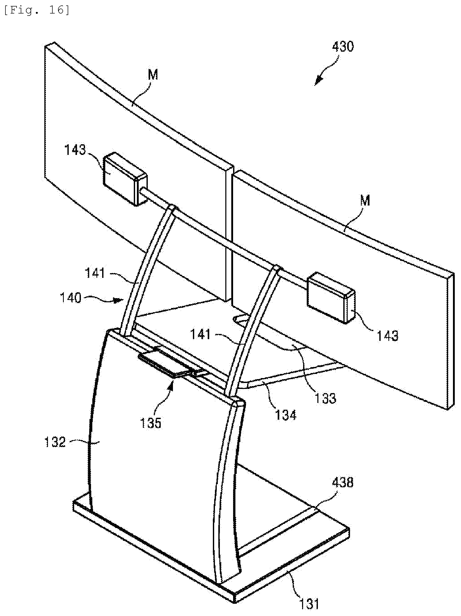
[0103] FIG. 16 illustrates a monitor-supporting desk unit of a complex sliding desk system according to a fifth embodiment of the present invention.
[0104] Referring to FIG. 16, a monitor-supporting desk unit 430 applicable to the complex sliding desk system according to the embodiment may also include a unit base 131, a column 132, a desk plate 134, and a monitor supporting part 140.
[0105] Column-forward/backward-moving units 438 that are connected to the column 132 and serve to move the column 132 forward and backward are provided on the unit base 131. The column-forward/backward-moving units 438 may be provided, for example, in an LM guide form or the like. When the column-forward/backward-moving units 438 are applied, the dual monitor (M) may be moved closer or farther away, so that convenience of use may increase.
[0106] Since the complex sliding desk system according to the embodiment has a compact and simple structure, manufacturing or purchasing costs may be reduced, thereby increasing market penetration thereof. Further, convenience of use may be greatly improved, compared with conventional cases, because work may be performed in the most ideal posture on the waist of the human body, such as performing work in a lying posture.
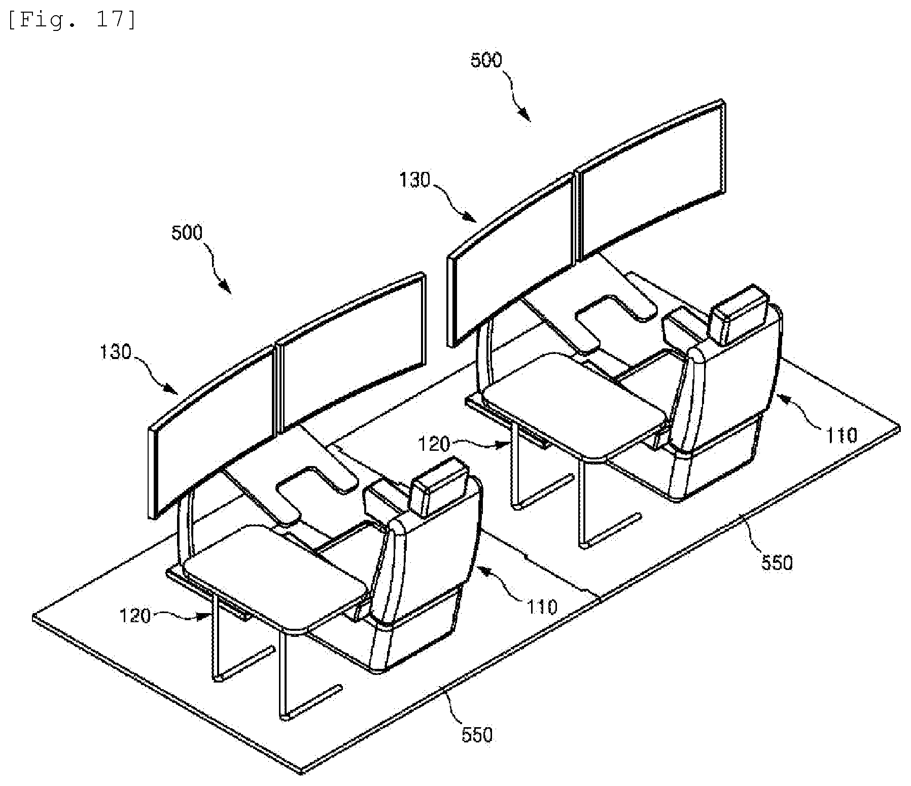
[0107] FIG. 17 illustrates a complex sliding desk system according to a sixth embodiment of the present invention, and FIG. 18 illustrates an exploded view of the complex sliding desk system of FIG. 17.
[0108] Referring to FIG. 17, a complex sliding desk system 500 according to the sixth embodiment of the present invention may also include chair units 110, side table units 120, and monitor-supporting desk units 130 arranged in an optimal combination.
[0109] In addition, the chair units 110, the side table units 120, and the monitor-supporting desk units 130 are mounted at optimal positions of the chair unit-supporting bases 550.
[0110] Concave-convex protrusions 551 are provided on one side of one of the chair unit-supporting bases 550 having the structure, and concave-convex grooves 552 are provided on one side of the other one of the chair unit-supporting bases 550, so that the concave-convex protrusions 551 may be fitted into the concave-convex grooves 552.
[0111] When the concave-convex protrusions 551 and the concave-convex grooves 552 are formed on the chair unit-supporting bases 550 as in the embodiment, construction work thereof is convenient and neat finishing work is possible.
[0112] Since the complex sliding desk system according to the embodiment has a compact and simple structure, manufacturing or purchasing costs may be reduced, thereby increasing market penetration thereof. Further, convenience of use may be greatly improved, compared with conventional cases, because work may be performed in the most ideal posture on the waist of the human body, such as performing work in a lying posture.
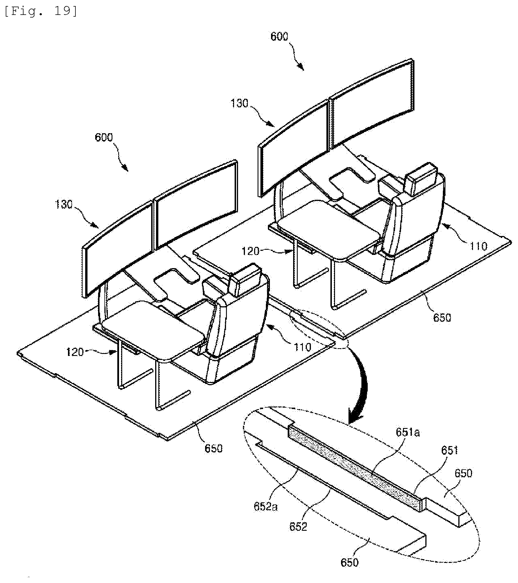
[0113] FIG. 19 illustrates a complex sliding desk system according to a seventh embodiment of the present invention.
[0114] Referring to FIG. 19, a complex sliding desk system 500 according to the seventh embodiment of the present invention may also include chair units 110, side table units 120, and monitor-supporting desk units 130 arranged in an optimal combination.
[0115] In addition, the chair units 110, the side table units 120, and the monitor-supporting desk units 130 are mounted at optimal positions on the chair unit-supporting bases 650.
[0116] Concave-convex protrusions 651 are provided on one side of one of the chair unit-supporting bases 650, and concave-convex grooves 652 are provided on one side of the other one of the chair unit-supporting bases 650, so that the concave-convex protrusions 651 may be fit into the concave-convex grooves 652, as in the above embodiment.
[0117] Magnets 651a and 652a are respectively provided on ends of the concave-convex protrusions 651 and the concave-convex grooves 652.
[0118] When the magnets 651a and 652a are respectively provided on ends of the concave-convex protrusions 651 and the concave-convex grooves 652 as in the embodiment, it is easy to install the chair unit-supporting bases 650 in a lateral direction due to the magnetic force thereof, and the bonding force therebetween after the installation increases.
[0119] Since the complex sliding desk system according to the embodiment has a compact and simple structure, manufacturing or purchasing costs may be reduced, thereby increasing market penetration thereof. Further, convenience of use may be greatly improved, compared with conventional cases, because work may be performed in the most ideal posture on the waist of the human body, such as performing work in a lying posture.
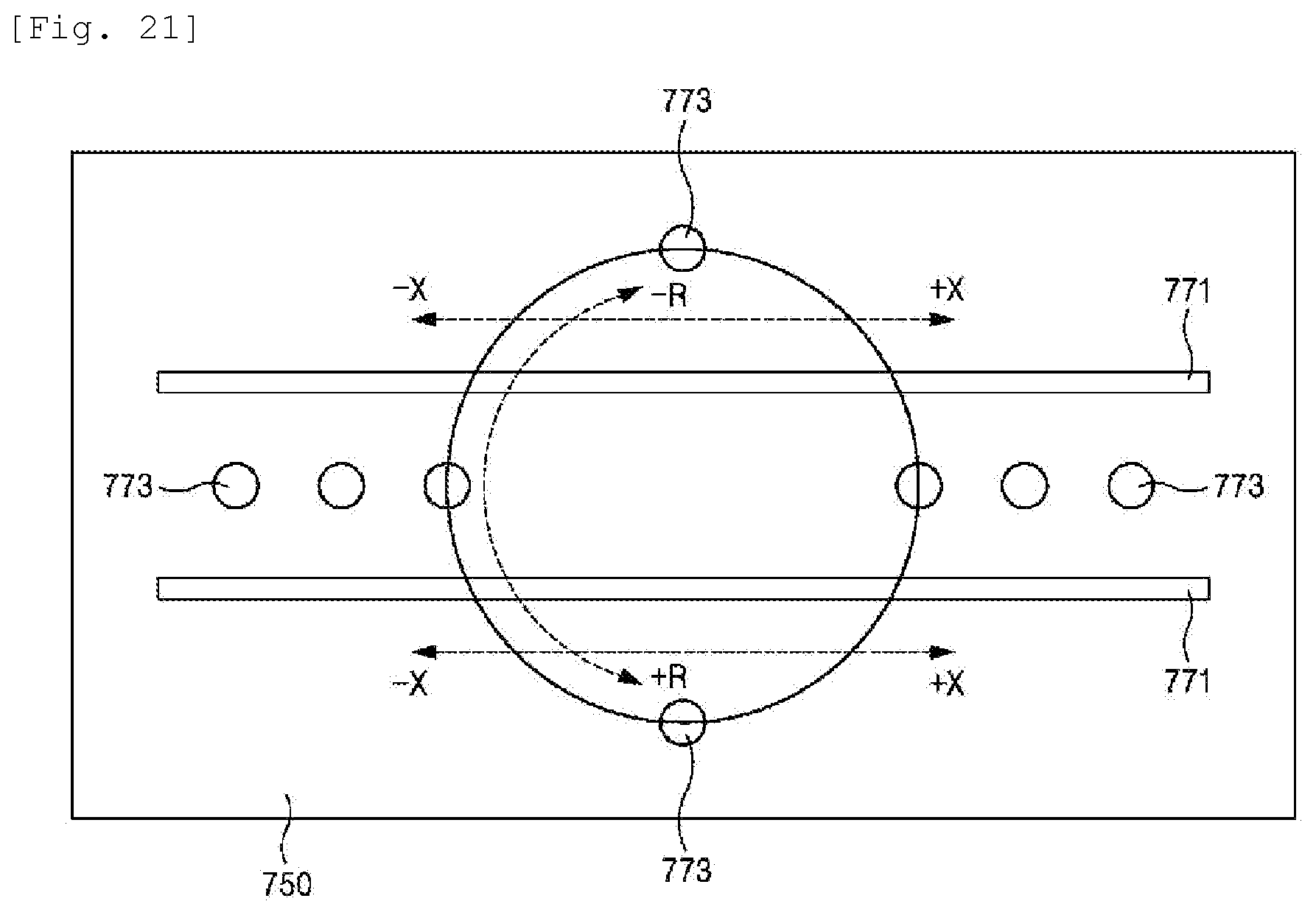
[0120] FIG. 20 illustrates a plan of a chair unit and a chair unit-supporting base of a complex sliding desk system according to an eighth embodiment of the present invention, and FIG. 21 illustrates a plan view of the chair unit-supporting base illustrated in FIG. 20.
[0121] Referring to the drawings, a chair unit 710 may be supported by a chair unit-supporting base 750. Here, a pair of rails 771 that are rail-coupled with the chair unit 710 and thus serve to move the chair unit 710 in a +X or -X axis direction, i.e., in a linear direction, are provided on the chair unit-supporting base 750. Therefore, it is easy to move the chair unit 710 in a +X or -X axis direction.
[0122] However, it is difficult to fix a movement position of the chair unit 710 when the rails 771 are applied alone. That is, it is necessary to fix the chair unit 710 to a desired position after moving the chair unit 710 to the desired position. For this, a plurality of ball plungers 773 may be provided. The ball plungers 773 allow smooth movement and stoppage of the chair unit 710 due to a ball/spring structure thereof.
[0123] In this embodiment, the ball plungers 773 may be applied inside the rails 771, and a portion of the ball plungers 773 may be provided outside the rails 771. The ball plungers 773 provided inside and outside the rails 771 may rotatably move the chair unit 710 in a +R or -R axis direction.
[0124] Since the complex sliding desk system according to the embodiment has a compact and simple structure, manufacturing or purchasing costs may be reduced, thereby increasing market penetration thereof. Further, convenience of use may be greatly improved, compared with conventional cases, because work may be performed in the most ideal posture on the waist of the human body, such as performing work in a lying posture.
[0125] FIG. 22 illustrates a perspective view of a complex sliding desk system according to a ninth embodiment of the present invention.
[0126] Referring to FIG. 22, a complex sliding desk system 800 according to the ninth embodiment of the present invention may also include a chair unit 810, a side table unit 820, a monitor-supporting desk unit 830, and a chair unit-supporting base 850 for supporting the chair unit 810 and the monitor-supporting desk unit 830.
[0127] The chair unit 810 may be operated so as to allow a lying posture slightly titled from a sitting posture as illustrated in the drawing.
[0128] The monitor-supporting desk unit 830, which is a structure for supporting a dual monitor (M), may include a column 832, a desk plate 834, and a monitor supporting part 840.
[0129] Here, the desk plate 834 may approach the chair unit 810 by being folded or unfolded by foldable arms 835. In addition, the monitor supporting part 840 also moves along an arc line with respect to the column 832 so that the dual monitor (M) approaches the chair unit 810.
[0130] When such a structure is applied, the dual monitor (M) may be viewed in a more relaxed posture by positioning the desk plate 834 and the dual monitor (M) to approach a user after lying down the chair unit 810, as illustrated in the drawing. In particular, since work may be performed in the most ideal posture on the waist of the human body, such as performing work in a lying posture, according to the embodiment, convenience of use may be greatly improved.
[0131] While the present invention has been described referring to the preferred embodiments, those skilled in the art will appreciate that many modifications and changes can be made to the present invention without departing from the spirit and scope of the present invention. Therefore, it should be understood that the modifications and changes are included in the claims of the present invention.
* * * * *
D00000
D00001
D00002
D00003
D00004
D00005
D00006
D00007
D00008
D00009
D00010
D00011
D00012

D00013
D00014

D00015
D00016
D00017
D00018

D00019
D00020

D00021
D00022

XML
uspto.report is an independent third-party trademark research tool that is not affiliated, endorsed, or sponsored by the United States Patent and Trademark Office (USPTO) or any other governmental organization. The information provided by uspto.report is based on publicly available data at the time of writing and is intended for informational purposes only.
While we strive to provide accurate and up-to-date information, we do not guarantee the accuracy, completeness, reliability, or suitability of the information displayed on this site. The use of this site is at your own risk. Any reliance you place on such information is therefore strictly at your own risk.
All official trademark data, including owner information, should be verified by visiting the official USPTO website at www.uspto.gov. This site is not intended to replace professional legal advice and should not be used as a substitute for consulting with a legal professional who is knowledgeable about trademark law.