Sole Structure And An Article Of Footwear
PISANO; Nicholas ; et al.
U.S. patent application number 15/974793 was filed with the patent office on 2019-11-14 for sole structure and an article of footwear. The applicant listed for this patent is C & J CLARK INTERNATIONAL LIMITED. Invention is credited to Lance BURWELL, Nicholas PISANO.
| Application Number | 20190343227 15/974793 |
| Document ID | / |
| Family ID | 66476640 |
| Filed Date | 2019-11-14 |


| United States Patent Application | 20190343227 |
| Kind Code | A1 |
| PISANO; Nicholas ; et al. | November 14, 2019 |
SOLE STRUCTURE AND AN ARTICLE OF FOOTWEAR
Abstract
A sole structure for an article of footwear. The sole structure comprises a sole component; and an insole, the insole being mounted to the sole component so as to define a cavity within the sole structure, the insole comprising a resiliently deformable diaphragm element that is constructed and arranged to force air through the cavity when depressed.
| Inventors: | PISANO; Nicholas; (Waltham, MA) ; BURWELL; Lance; (Hudson, MA) | ||||||||||
| Applicant: |
|
||||||||||
|---|---|---|---|---|---|---|---|---|---|---|---|
| Family ID: | 66476640 | ||||||||||
| Appl. No.: | 15/974793 | ||||||||||
| Filed: | May 9, 2018 |
| Current U.S. Class: | 1/1 |
| Current CPC Class: | A43B 13/206 20130101; A43B 7/144 20130101; A43B 13/12 20130101; A43B 13/141 20130101; A43B 13/125 20130101; A43B 7/081 20130101; A43B 7/088 20130101; A43B 13/38 20130101; A43B 13/122 20130101; A43B 7/06 20130101; A43B 13/181 20130101 |
| International Class: | A43B 13/20 20060101 A43B013/20; A43B 13/12 20060101 A43B013/12; A43B 13/14 20060101 A43B013/14; A43B 13/38 20060101 A43B013/38 |
Claims
1. A sole structure for an article of footwear, the sole structure comprising: a sole component; and an insole, the insole being mounted to the sole component so as to define a cavity within the sole structure, the insole comprising a resiliently deformable diaphragm element that is constructed and arranged to force air through the cavity when depressed.
2. A sole structure according to claim 1, wherein the sole component is a midsole.
3. A sole structure according to claim 1, wherein the sole component is an outsole.
4. A sole structure according to claim 1, wherein the resiliently deformable diaphragm element comprises a first surface that protrudes above the insole and a second surface recessed into the insole.
5. A sole structure according to claim 1, wherein the resiliently deformable diaphragm element is located at a heel region of the insole.
6. A sole structure according to claim 1, wherein the sole component comprises an air pump formation constructed and arranged to interact with the resiliently deformable diaphragm element when the resiliently deformable diaphragm element is depressed.
7. A sole structure according to claim 6, wherein the air pump formation comprises one or more resilient pillars arranged on a first surface of the sole component.
8. A sole structure according to claim 1, wherein the sole component comprises a plurality of resilient pillars arranged on a first surface of the sole component, the plurality of resilient pillars protruding into the cavity, thereby dividing the cavity into a series of air circulation channels.
9. A sole structure according to claim 8, wherein the resiliently deformable diaphragm element forces air through the air circulation channels when depressed by deforming at least one of the plurality of resilient pillars, thereby generating a pumping action.
10. A sole structure according to claim 8, wherein one or more of the plurality of resilient pillars is disposed in a first region of the sole structure, and one or more of the plurality of resilient pillars is disposed in a second region of the sole structure.
11. A sole structure according to claim 10, wherein the one or more resilient pillars disposed in the first region comprise a generally teardrop shaped cross section.
12. A sole structure according to claim 9, wherein the first region is a toe region and/or a midfoot region of the sole structure.
13. A sole structure according to claim 9, wherein the one or more resilient pillars disposed in the second region comprise a generally lens shaped cross section.
14. A sole structure according to claim 13, wherein the second region is a heel region of the sole structure.
15. A sole structure according to claim 1, wherein the sole component comprises a plurality of air passages for increasing air flow into the cavity of the sole structure, and wherein the sole structure comprises an insert having a plurality of tubes, each tube being inserted into an air passage.
16. A sole structure according to claim 15, wherein the insert comprises a base and the plurality of tubes is mounted onto the base.
17. A sole structure according to claim 15, wherein the sole component comprises a hollow for housing the insert.
18. An article of footwear comprising a sole structure for an article of footwear, the sole structure comprising: a sole component; and an insole, the insole being mounted to the sole component so as to define a cavity within the sole structure, the insole comprising a resiliently deformable diaphragm element that is constructed and arranged to force air through the cavity when depressed.
19. An article of footwear according to claim 18, wherein the sole component comprises an air pump formation constructed and arranged to interact with the resiliently deformable diaphragm element when the resiliently deformable diaphragm element is depressed.
20. An article of footwear according to claim 18, wherein the sole component comprises a plurality of resilient pillars arranged on a first surface of the outsole, the plurality of resilient pillars protruding into the cavity, thereby dividing the cavity into a series of air circulation channels.
Description
TECHNICAL FIELD
[0001] The present disclosure relates to a sole structure for an article of footwear, and an article of footwear.
BACKGROUND
[0002] An article of footwear, such as a shoe, a cleat, a sandal, a boot or the like, is used to protect and provide comfort to a user's foot. An article of footwear is typically formed from many components including an upper and a sole structure. The upper and the sole structure are bound together during the shoemaking process to form a space for receiving a user's foot. The sole structure includes an outsole as its bottommost surface. The outsole comes into direct contact with the ground and so it is normally formed from a hardwearing material. The sole structure may also include an insole (also known as a footbed), which is a layer of material inserted into the space formed between the upper and the outsole. In normal use of the article of footwear, a user's foot rests on the insole. Some articles of footwear also include a midsole, which is a layer of material provided between the insole and the outsole. The midsole is used to enhance comfort and improve shock absorption.
SUMMARY
[0003] According to a first aspect disclosed herein, there is provided a sole structure for an article of footwear, the sole structure comprising: a sole component; and an insole, the insole being mounted to the sole component so as to define a cavity within the sole structure, the insole comprising a resiliently deformable diaphragm element that is constructed and arranged to force air through the cavity when depressed.
[0004] In an example, the sole component is a midsole.
[0005] In an example, the sole component is an outsole.
[0006] In an example, the resiliently deformable diaphragm element comprises a first surface that protrudes above the insole and a second surface recessed into the insole.
[0007] In an example, the resiliently deformable diaphragm element is located at a heel region of the insole.
[0008] In an example, the sole component comprises an air pump formation constructed and arranged to interact with the resiliently deformable diaphragm element when the resiliently deformable diaphragm element is depressed.
[0009] In an example, the air pump formation comprises one or more resilient pillars arranged on a first surface of the sole component.
[0010] In an example, the sole component comprises a plurality of resilient pillars arranged on a first surface of the sole component, the plurality of resilient pillars protruding into the cavity, thereby dividing the cavity into a series of air circulation channels.
[0011] In an example, the resiliently deformable diaphragm element forces air through the air circulation channels when depressed by deforming at least one of the plurality of resilient pillars, thereby generating a pumping action.
[0012] In an example, one or more of the plurality of resilient pillars is disposed in a first region of the sole structure, and one or more of the plurality of resilient pillars is disposed in a second region of the sole structure.
[0013] In an example, the one or more resilient pillars disposed in the first region comprise a generally teardrop shaped cross section.
[0014] In an example, the first region is a toe region and/or a midfoot region of the sole structure.
[0015] In an example, the one or more resilient pillars disposed in the second region comprise a generally lens shaped cross section.
[0016] In an example, the second region is a heel region of the sole structure.
[0017] In an example, the sole component comprises a plurality of air passages for increasing air flow into the cavity of the sole structure, and wherein the sole structure comprises an insert having a plurality of tubes, each tube being inserted into an air passage.
[0018] In an example, the insert comprises a base and the plurality of tubes is mounted onto the base.
[0019] In an example, the sole component comprises a hollow for housing the insert.
[0020] According to a second aspect disclosed herein, there is provided an article of footwear comprising a sole structure for an article of footwear, the sole structure comprising: a sole component; and an insole, the insole being mounted to the sole component so as to define a cavity within the sole structure, the insole comprising a resiliently deformable diaphragm element that is constructed and arranged to force air through the cavity when depressed.
[0021] In an example, the sole component comprises an air pump formation constructed and arranged to interact with the resiliently deformable diaphragm element when the resiliently deformable diaphragm element is depressed.
[0022] In an example, the sole component comprises a plurality of resilient pillars arranged on a first surface of the sole component, the plurality of resilient pillars protruding into the cavity, thereby dividing the cavity into a series of air circulation channels.
BRIEF DESCRIPTION OF THE DRAWINGS
[0023] To assist understanding of the present disclosure and to show how embodiments may be put into effect, reference is made by way of example to the accompanying drawings in which:
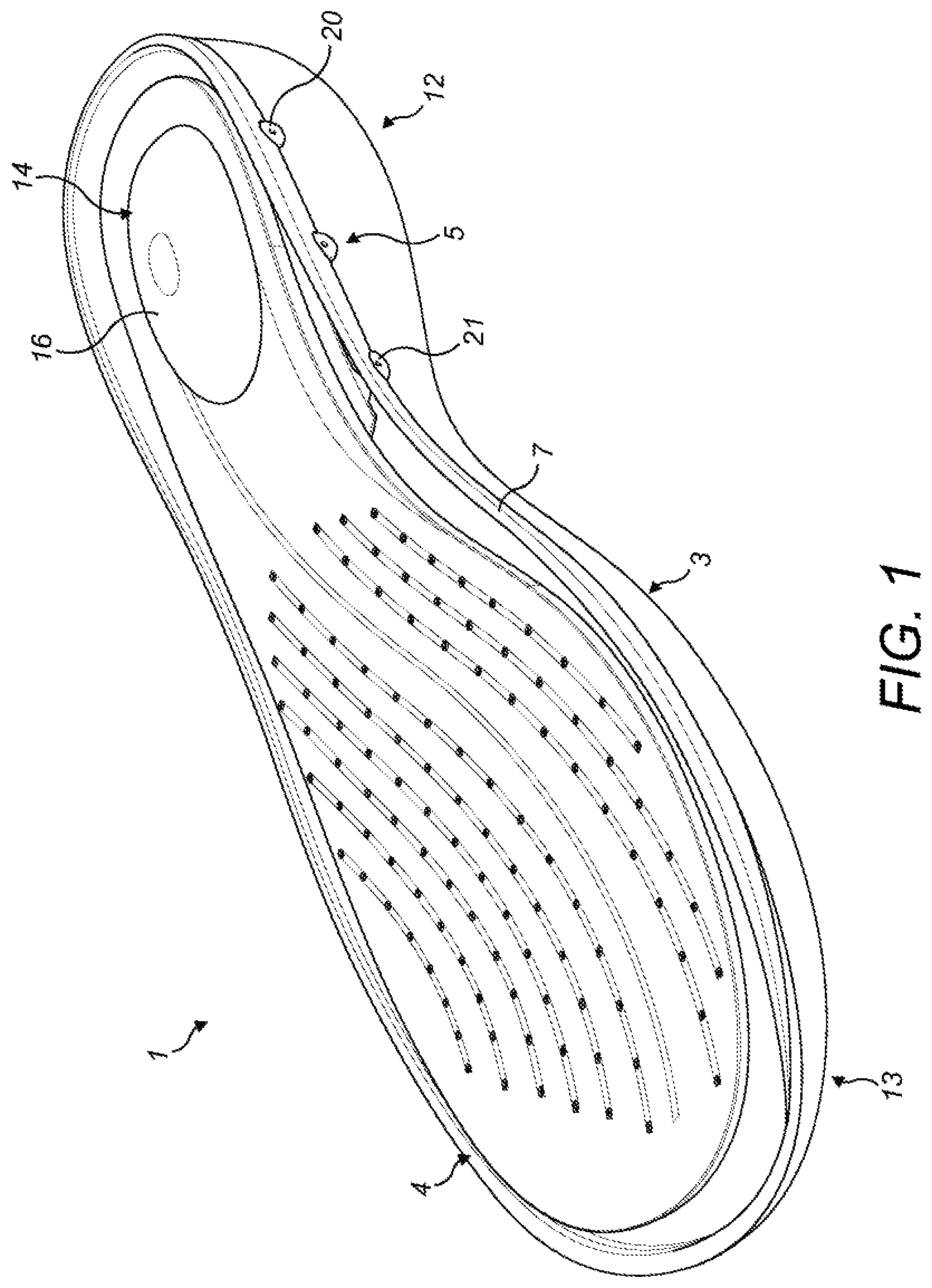
[0024] FIG. 1 shows schematically a perspective view of an example of a sole structure for an article of footwear, the sole structure including an insole, a sole component and an insert;
[0025] FIG. 2 shows schematically a perspective view of the sole component and the insert shown in FIG. 1;
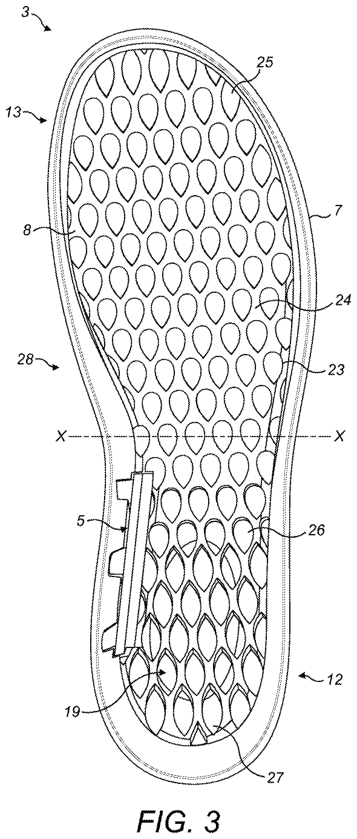
[0026] FIG. 3 shows schematically a plan view of the sole component shown in FIGS. 1 and 2;
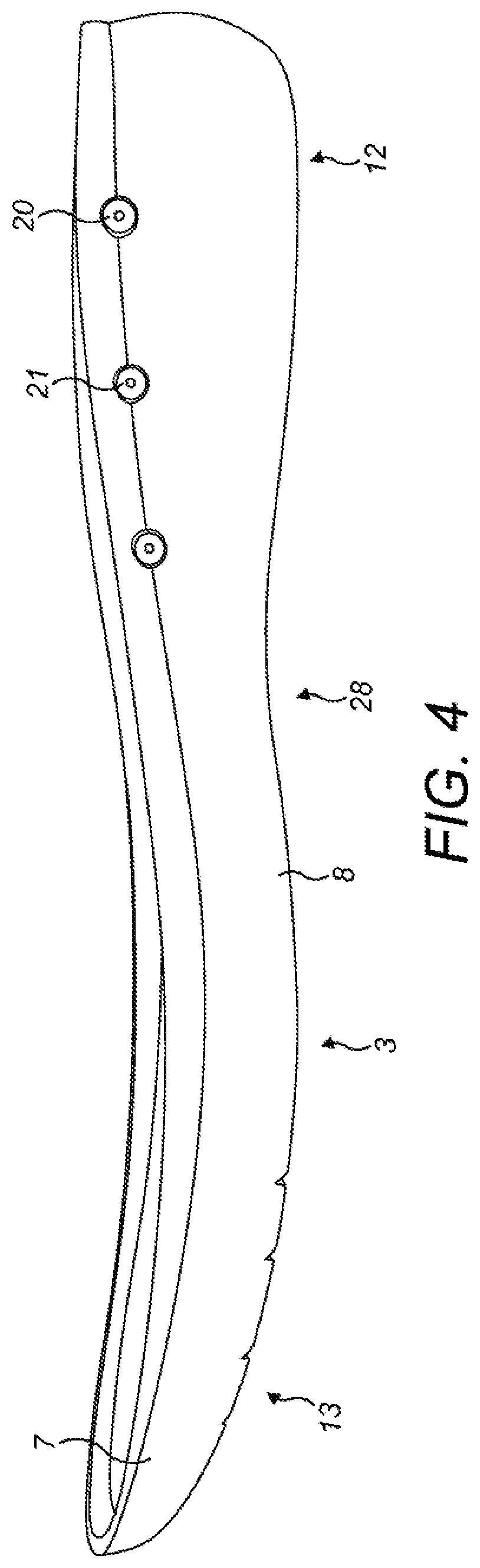
[0027] FIG. 4 shows schematically a side view of the sole component shown in FIGS. 1-3;
[0028] FIG. 5 shows schematically a longitudinal cross section view of the sole component shown in FIG. 3, along the line X-X, with the insole mounted to the sole component.
[0029] FIG. 6 shows schematically a perspective view of the insert shown in FIGS. 1-4;
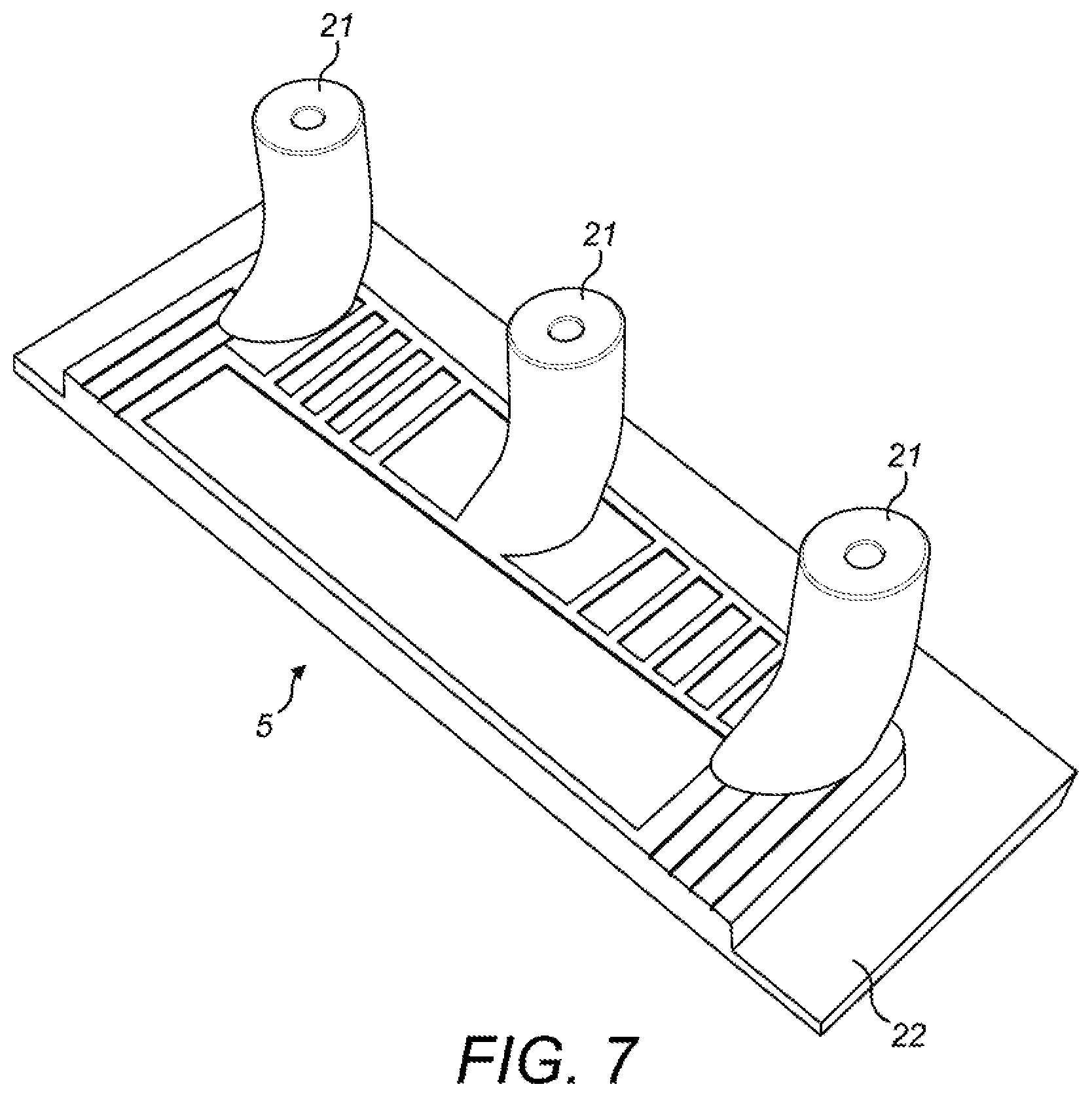
[0030] FIG. 7 shows schematically a perspective view of the insert shown in FIGS. 1-4;
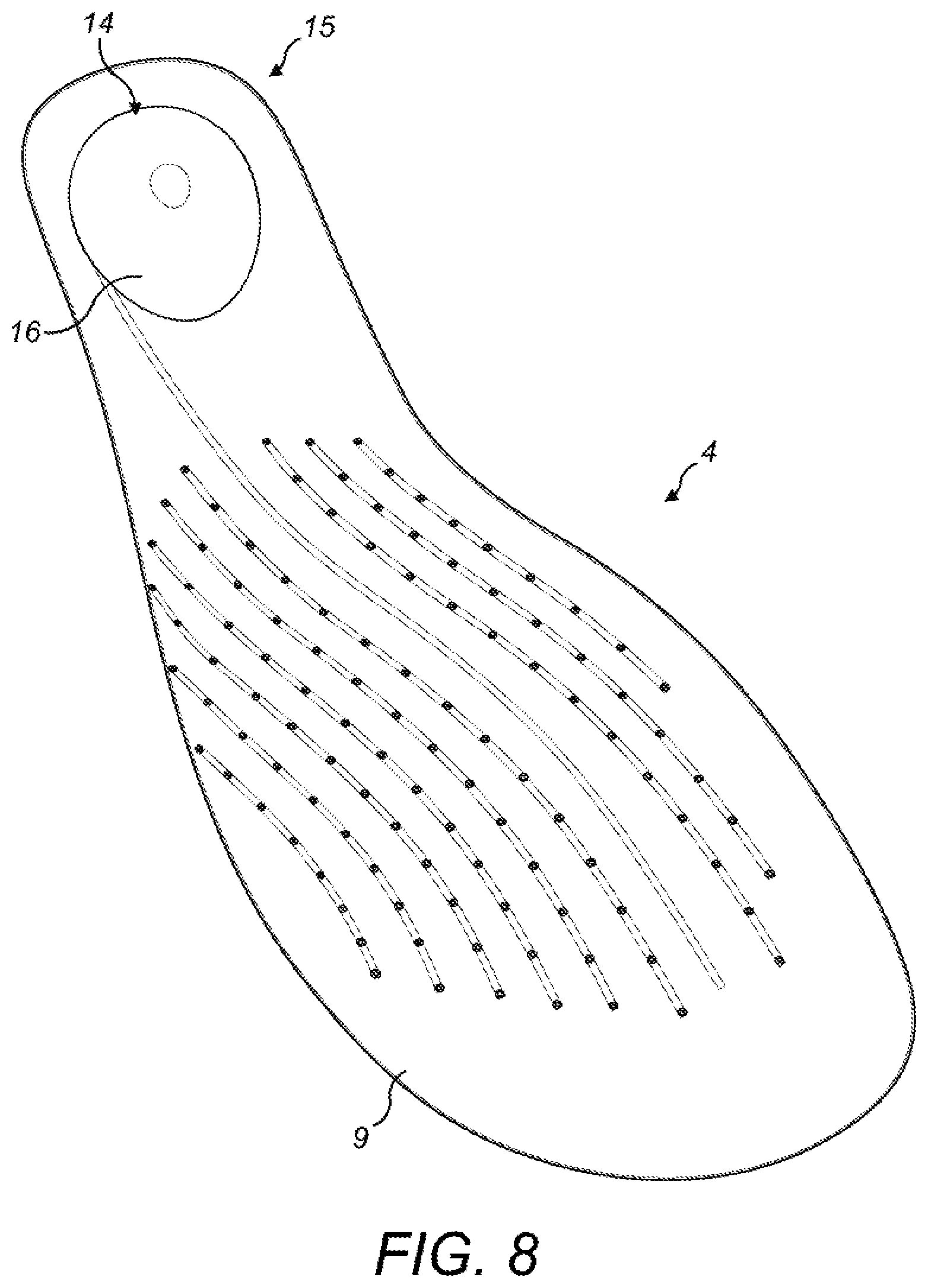
[0031] FIG. 8 shows schematically a front perspective view of the insole shown in FIG. 1; and
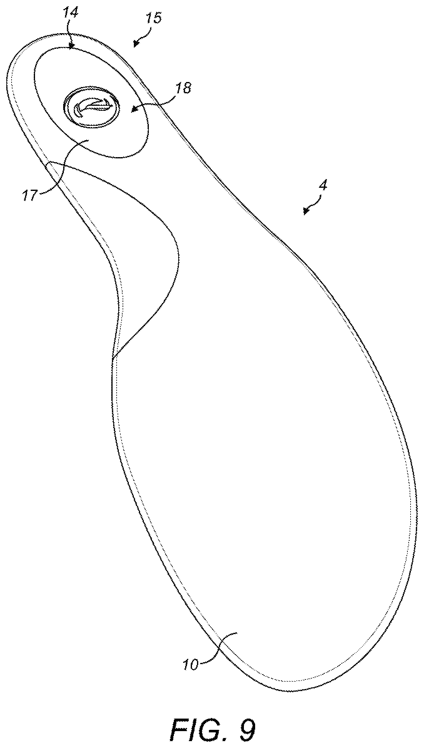
[0032] FIG. 9 shows schematically a rear perspective view of the insole shown in FIG. 8.
DETAILED DESCRIPTION
[0033] An article of footwear, such as a shoe, a cleat, a sandal, a boot or the like, is used to protect and provide comfort to a user's foot. An article of footwear is typically formed from many components including an upper and a sole structure. The upper and the sole structure are bound together during the shoemaking process to form a space for receiving a user's foot. The sole structure includes an outsole as its bottommost surface. The outsole comes into direct contact with the ground and so it is normally formed from a hardwearing material. The sole structure may also include an insole (also known as a footbed), which is a layer of material inserted into the space formed between the upper and the outsole. In normal use of the article of footwear, a user's foot rests on the insole. Some articles of footwear also include a midsole, which is a layer of material provided between the insole and the outsole. The midsole is used to enhance comfort and improve shock absorption.
[0034] An article of footwear is designed and manufactured to suit a specific need or purpose and so it must have particular properties. One important property is that the article of footwear is comfortable for a user to wear. Therefore, the sole structure of an article of footwear should be able to absorb at least some of the shock experienced when a user walks or runs on a hard surface such as concrete. Further, the sole structure of an article of footwear should also allow heat generated by a user's foot to easily dissipate out of the shoe, so as to cool the user's foot.
[0035] FIG. 1 shows schematically a sole structure 1 for an article of footwear 2. In this example, the article of footwear 2 is a shoe. In another example, the article of footwear is a boot, a cleat, a sandal or the like. The article of footwear 2 includes an upper (not shown) mounted to a sole structure 1. In this example, the sole structure 1 includes a sole component, which in this example is a midsole 3 (shown schematically in FIGS. 2-5), an insole 4 (also known as a footbed, and shown schematically in FIGS. 8 and 9) and an insert 5 (shown schematically in FIGS. 6 and 7). The sole structure 1 also includes an outsole (not shown) attached to the bottom of the midsole 3. The outsole may be formed from a rubber material. The outsole is the part of the sole structure that contacts with the ground during use of the article of footwear 2.
[0036] In another example, the sole component is an outsole. Thus, the sole structure 1 includes only an insole 4 and an outsole. The outsole may have one or more, or all of the features of the midsole 3 as described herein.
[0037] The article of footwear 2 is assembled by first implanting the insert 5 into a hollow 6 provided in the midsole 3. The upper is then mounted to the sole structure 1 by various techniques, such as stitching and/or cementing. The insole 4 is then inserted into the space defined between the upper and the midsole 3. In an example, the insole 4 may be temporality mounted or secured to the midsole 3 whilst it is in the space defined between the upper and the midsole 3 by using for example an adhesive. This helps to prevent the insole 4 from moving when the article of footwear 2 is worn by a user.
[0038] As is shown particularly in FIG. 2, the midsole 3 has a side wall 7 surrounding a first surface, which acts as a base 8.
[0039] The insole 4 is a removable component and is provided to improve the comfort and shock absorption provided by the sole structure 1. In use, when the article of footwear 2 is in an assembled state, the insole 4 sits on the midsole 3. The insole 4 has a first surface, which is the uppermost surface 9 of the insole 4 when it is mounted to the midsole 3 (shown in FIG. 8). The insole 4 also has a second surface, which is the lowermost surface 10 of the insole 4 when it is mounted to the midsole 3 (shown in FIG. 9).
[0040] When the article of footwear 2 is in an assembled state, the insole 4 is mounted to the midsole 3 such that a cavity 11 is defined between the side wall 7 and the base 8 of the midsole 3, and the lowermost surface 10 of the insole 4. The cavity 11 extends from the heel region 12 of the sole structure 1 through to the toe region 13 of the sole structure 1. Air can circulate within the cavity 11, which can help to cool down the feet of a user that is wearing the article of footwear 2.
[0041] The insole 4 includes a diaphragm element 14. The diaphragm element 14 is constructed and arranged to force air through the cavity 11 when the diaphragm element 14 is depressed. The diaphragm element 14 is provided at the heel region 15 of the insole 4. The diaphragm element 14 is thus located so that it can be depressed by the heel of a user's foot pressing against it during use of the article of footwear 2 by a user.
[0042] The diaphragm element 14 has a foot contact surface 16 that protrudes above the uppermost surface 9 of the insole 4. The foot contact surface 16 faces towards a user's heel and is the surface that comes into contact a user's foot. The diaphragm element 14 has a corresponding pumping surface 17. In this example, the pumping surface 17 is recessed into the lowermost surface 10 of the insole 4, defining a chamber 18.
[0043] In use, when the foot contact surface 16 of the diaphragm element 14 is pressed by a user's foot (e.g. when a user has taken a step when wearing the article of footwear 2) the diaphragm element 14 deforms towards the midsole 3. In this example, deformation of the diaphragm element 14 pushes the pumping surface 17 towards the midsole 3, which reduces the volume of the chamber 18. This forces at least some of the air that was contained within the chamber 18 into and through the cavity 11 that is between the insole 4 and the midsole 3. When the user's foot releases from the foot contact surface 16 of the diaphragm element 14 (e.g. when a user has lifted their foot off of the ground to take another step) the diaphragm element 14 reforms back to its original shape (as is shown in FIGS. 8 and 9). In this example, the pumping surface 17 is released so that it can move away from the midsole 3, which increases the volume of the chamber 18. The diaphragm element 14 is now in a position where it can once again be pressed to force air into the cavity 11. The repeated pressing and releasing of the diaphragm element 14 as a user walks thus causes a pumping effect that forces air through the cavity 11 between the insole 4 and the midsole 3. The pumping effect may reduce the temperature of the user's feet, thereby improving making the article of footwear 2 much more comfortable for a user to wear.
[0044] The diaphragm element 14 (or at least a portion thereof) is resiliently deformable. To this end, in this example, the diaphragm element 14 is formed from a one or more resiliently deformable materials. In one example, the diaphragm element 14 is formed from polyurethane foam. Using polyurethane foam is particularly advantageous due it its antimicrobial properties and the level of comfort it provided to the wearer. In an example, the diaphragm element 14 may be formed from the same material(s) from which the remainder of the insole 4 is formed. In an example, the diaphragm element 14 have a structure and/or a shape that enhances the above mentioned pumping effect. In this example, the diaphragm element, has an ovular profile. In this example, the foot contact surface 16 has a convex shape. In this example, the pumping surface 17 has a concave shape. These structural features help to improve the pumping effect provided by the diaphragm element 14. In another example, the diaphragm element have a different profile and/or shape, provided that it does not hinder the pumping effect.
[0045] In an example, the midsole 3 includes an air pump formation 19. The air pump formation 19 is formed on the midsole 3 so that it protrudes above the base 8 of the midsole 3. This allows the air pump formation 19 to interact with the diaphragm element 14 when the diaphragm element 14 is depressed. In this example, the air pump formation 19 is integrally formed on the base 8 of the midsole 3. In another example, the air pump formation 19 is a separate element that is attached to the base 8 of the midsole 3 by various techniques, such as being stitched, glued or screwed.
[0046] The air pump formation 19 may interact with the diaphragm element 14 by engaging or abutting with the diaphragm element 14 when the diaphragm element 14 is depressed. This engagement reduces the distance that the diaphragm element 14 must be depressed so that the volume of the chamber 18 is reduced sufficiently to force air from the chamber 18 into the cavity 11. In addition, the air pump formation 19 limits the depth to which the diaphragm element 14 can be depressed, so that it can more easily reflect back to its normal non-depressed position. In an example, the diaphragm element 14, when depressed, may just move towards the air pump formation 19. In that example, it is not necessary for the diaphragm element 14 to actually contact with the air pump formation 19.
[0047] One or more air passages 20 may be formed in the side wall 7 of the midsole 3. In this example, the side wall 7 of the midsole 3 contains a plurality of air passages 20. The one or more air passages 20 improve the pumping effect of the diaphragm element 14 by allowing cool air from outside of the cavity 11 to be drawn into the cavity 11 and directed from the heel region 12 towards the toe region 13 of the sole structure 1. In this example, the plurality of air passages 20 are located at the heel region 12 of the sole structure 1. This improves the effectiveness of the air passages 20 since they are provided near to the diaphragm element 14.
[0048] The insert 5 may have a plurality of tubes 21. When the article of footwear 2 is in its assembled state, with the insert 5 housed within the hollow 6 in the midsole 3, each tube 21 of the insert 5 is inserted into an air passage 20. The plurality of tubes 21 support the air passages 20 and help to keep them open whilst a user is using the article of footwear 2. In this example, the plurality of tubes 21 is mounted to a base plate 22. When the insert 5 is positioned in the hollow 6, the base plate 22 retains the plurality of tubes 21 within the hollow 6 so that they do not fall out through the air passages 20.
[0049] In this example, the hollow 6 has a shape that generally corresponds to the shape of the base 22 of the insert 5.
[0050] In an example, the midsole 3 includes a plurality of resilient pillars 23 provided across an uppermost surface 24 of the base 7 of the midsole 3. The pillars 23 are formed from a resilient material. In on example, the pillars 23 are each formed from ethylene-vinyl acetate, also known as EVA. This allows each of the pillars 23 to deform in response to pressure (e.g. from a user's foot pressing on the pillars 23 as user walks), and then reform back to its original shape once the pressure has been removed or reduced. The plurality of resilient pillars 23 support the insole 4 and thus the user's foot when the user is wearing the article of footwear 2.
[0051] In this example, the plurality of resilient pillars 23 are integrally formed with the midsole 3. In other examples, the plurality of resilient pillars 23 may attached to the uppermost surface 24 of the base 7 of the midsole 3 by another method. For example, the plurality of resilient pillars 23 may be stitched, glued or screwed to the uppermost surface 24 of the base 7 of the midsole 3.
[0052] The plurality of resilient pillars 23 may be provided in a regular pattern. In another example, the plurality of resilient pillars 23 may be provided in an irregular pattern. In a further example, the plurality of resilient pillars 6 may be provided partially in a regular pattern and partially in an irregular pattern.
[0053] When the article of footwear 2 is in its assembled state, the plurality of resilient pillars 23 may extend from the uppermost surface 24 of the base 7 to the upper. Indeed, in this example, a top surface 25 of each of the plurality of resilient pillars 23 is in contact with a bottom surface of the upper when the article of footwear 2 is assembled. The plurality of resilient pillars 23 are thus provided within the cavity 11 and divide the cavity 11 from a singular open space into a series of air circulation channels. That is, the air circulation channels are the passages in between the pillars 23.
[0054] Since the combined cross sectional area of the air circulation channels (i.e. the cross sectional area between the pillars 23) is smaller than the cross sectional area of the open cavity 11, the velocity of the air being forced through the cavity 11 having air circulation channels by the diaphragm element 14 is typically greater than the velocity of the air being forced through the open cavity 11. This provides an improved cooling effect.
[0055] Each of the plurality of resilient pillars 23 may have any particular shape, so long as the shape is suitable for providing support to a user's foot. In this example, the plurality of resilient pillars 23 are all generally cylindrical. This allows air to easily flow through the air circulation channels between the cylinders.
[0056] In an example, some of the plurality of resilient pillars 21 may have a teardrop cross section 26. A pillar having a teardrop cross section 26 can allow air to flow easily past the pillar 23 (and thus through an air circulation channel) in the direction from the narrow end of the teardrop to the rounded end, but not easily past the pillar 23 (and thus through an air circulation channel) in the direction from the rounded end of the tear drop to the narrow end. In one example, one or more pillars having a teardrop cross section 26 may be oriented so that the narrow end of the teardrop cross section 26 faces towards the heel region 12 of the sole structure 1. Thus, in this orientation, the shape of a pillar having a teardrop cross section 26 allows air to flow easily in the air circulation channels in a heel to toe direction, but impedes air flow in the air circulation channels from a toe to heel direction.
[0057] In an example, some of the plurality of resilient pillars 23 may have a lens cross section 27. A pillar having a lens cross section 27 can allow air to flow easily past the pillar 23 (and thus through an air circulation channel) in both a heel to toe direction and in a toe to heel direction.
[0058] One or more of the resilient pillars 23 may be provided in a first region of the sole structure 1 and one or more of the resilient pillars 23 may be provided in a second region of the sole structure 1. In this example, the first region is the toe region 13 of the sole structure 1 and a midfoot region 28 of the sole structure 1, and the second region is the heel region 12 of the sole structure.
[0059] The one or more of the plurality of resilient pillars 23 that are provided in a region may all have a particular cross-section shape. In this example, the pillars 23 provided in the first region (which includes the toe region 13 and the midfoot region 28 of the sole structure 1) all have a teardrop cross section 26. In this example, the pillars 23 provided in the second region (which includes the heel region 12) all have a lens cross section 27.
[0060] In one example, the air pump formation 19 may be formed from one or more of the plurality of resilient pillars 23. The one or more pillars forming the air pump formation 19 have a greater height that the remaining pillars. This allows the pillars forming the air pump formation to interact with the diaphragm element 14 of the insole 4, without the other pillars interfering. When the air pump formation 19 is formed from one or more of the plurality of resilient pillars 23.
[0061] An advantage of the arrangement described above is the pumping effect of the diaphragm element 14 forces air to circulate around the cavity 11 beneath the insole 4 during normal use of the article of footwear 2. The air flowing through the cavity 11 cools the user's foot and thereby improves the comfort provided by the article of footwear 2. This cooling effect is particularly important in articles of footwear 1 designed for exercise, work etc., where a high level of movement is expected from a user.
[0062] The examples described herein are to be understood as illustrative examples of embodiments of the invention. Further embodiments and examples are envisaged. Any feature described in relation to any one example or embodiment may be used alone or in combination with other features. In addition, any feature described in relation to any one example or embodiment may also be used in combination with one or more features of any other of the examples or embodiments, or any combination of any other of the examples or embodiments. Furthermore, equivalents and modifications not described herein may also be employed within the scope of the invention, which is defined in the claims.
* * * * *
D00000
D00001
D00002
D00003
D00004
D00005
D00006
D00007
D00008
XML
uspto.report is an independent third-party trademark research tool that is not affiliated, endorsed, or sponsored by the United States Patent and Trademark Office (USPTO) or any other governmental organization. The information provided by uspto.report is based on publicly available data at the time of writing and is intended for informational purposes only.
While we strive to provide accurate and up-to-date information, we do not guarantee the accuracy, completeness, reliability, or suitability of the information displayed on this site. The use of this site is at your own risk. Any reliance you place on such information is therefore strictly at your own risk.
All official trademark data, including owner information, should be verified by visiting the official USPTO website at www.uspto.gov. This site is not intended to replace professional legal advice and should not be used as a substitute for consulting with a legal professional who is knowledgeable about trademark law.