Lithium Ion Solid-state Battery And Method For Producing The Same
TEMPEL; Hermann ; et al.
U.S. patent application number 16/462248 was filed with the patent office on 2019-11-07 for lithium ion solid-state battery and method for producing the same. The applicant listed for this patent is FORSCHUNGSZENTRUM JUELICH GMBH. Invention is credited to Lambertus G. J. DE HAART, Ruediger-A. EICHEL, Xin GAO, Hans KUNGL, Andreas MERTENS, Joseph MERTENS, Roland SCHIERHOLZ, Hermann TEMPEL, Shicheng YU.
| Application Number | 20190341597 16/462248 |
| Document ID | / |
| Family ID | 60654572 |
| Filed Date | 2019-11-07 |


| United States Patent Application | 20190341597 |
| Kind Code | A1 |
| TEMPEL; Hermann ; et al. | November 7, 2019 |
LITHIUM ION SOLID-STATE BATTERY AND METHOD FOR PRODUCING THE SAME
Abstract
A method for preparing a lithium ion solid-state accumulator comprising an anode, a cathode, and a solid-state electrolyte includes pressing and sintering pre-calcined electrolyte powder to an electrolyte layer. The pre-calcined electrolyte powder comprises at least one phosphate compound, at least one silicide compound, or at least one phosphorus sulfide. The method further includes applying, on both sides of the electrolyte layer, one electrode each. Prior to the application of the at least one electrode layer on a surface of the sintered electrolyte layer, first, at least one intermediate layer, and, then, on this intermediate layer, the electrode layer is applied. The at least one intermediate layer is a layer of electrolyte and anode material and/or a layer of electrolyte and cathode material.
| Inventors: | TEMPEL; Hermann; (Kreuzau, DE) ; YU; Shicheng; (Juelich, DE) ; KUNGL; Hans; (Heidelberg, DE) ; GAO; Xin; (Shanghai, CN) ; SCHIERHOLZ; Roland; (Cologne, DE) ; MERTENS; Andreas; (Cologne, DE) ; MERTENS; Joseph; (Alsdorf, DE) ; DE HAART; Lambertus G. J.; (Aachen, DE) ; EICHEL; Ruediger-A.; (Juelich, DE) | ||||||||||
| Applicant: |
|
||||||||||
|---|---|---|---|---|---|---|---|---|---|---|---|
| Family ID: | 60654572 | ||||||||||
| Appl. No.: | 16/462248 | ||||||||||
| Filed: | November 18, 2017 | ||||||||||
| PCT Filed: | November 18, 2017 | ||||||||||
| PCT NO: | PCT/DE2017/000391 | ||||||||||
| 371 Date: | May 20, 2019 |
| Current U.S. Class: | 1/1 |
| Current CPC Class: | H01M 4/0471 20130101; H01M 2/168 20130101; H01M 4/0407 20130101; H01M 4/5825 20130101; H01M 10/0525 20130101; H01M 10/052 20130101; H01M 2300/0071 20130101; H01M 4/043 20130101; H01M 10/0562 20130101; H01M 2/1673 20130101 |
| International Class: | H01M 4/04 20060101 H01M004/04; H01M 10/0525 20060101 H01M010/0525; H01M 2/16 20060101 H01M002/16 |
Foreign Application Data
| Date | Code | Application Number |
|---|---|---|
| Dec 21, 2016 | DE | 10 2016 015 191.9 |
Claims
1-15. (canceled)
16. A method for preparing a lithium ion solid-state accumulator comprising an anode, a cathode, and a solid-state electrolyte, the method comprising: pressing and sintering pre-calcined electrolyte powder to an electrolyte layer, wherein the pre-calcined electrolyte powder comprises at least one phosphate compound, at least one silicide compound, or at least one phosphorus sulfide; applying, on both sides of the electrolyte layer, one electrode each, wherein, prior to the application of at least one electrode layer on a surface of the sintered electrolyte layer, first, at least one intermediate layer, and, then, on this intermediate layer, the electrode layer is applied, wherein the at least one intermediate layer is a layer of electrolyte and anode material and/or a layer of electrolyte and cathode material.
17. The method according to claim 16, wherein, prior to application of the electrode layers on two surfaces of the sintered electrolyte layer, in each case, initially, an intermediate layer, and, then, on these intermediate layers, the respective electrode layers are applied.
18. The method according to claim 16, wherein an electrolyte powder with a mean grain size between 1 and 2,000 nm is used.
19. The method according to claim 16, wherein at least one electrode is applied by screen printing, offset, roll-to-roll, dipping bed, or inkjet printing.
20. The method according to claim 16, wherein the electrolyte layer has a layer thickness between 100 .mu.m and 800 .mu.m.
21. The method according to claim 16, wherein the at least one intermediate layer has a layer thickness between 1 and 10 .mu.m and.
22. A lithium ion solid-state accumulator, comprising: an anode, a cathode, and a solid-state electrolyte having a layer thickness between 100 .mu.m and 800 .mu.m, a first intermediate layer arranged between the solid state electrolyte and the anode, wherein the first intermediate layer comprises the electrolyte and anode material; and a second intermediate layer arranged between the solid electrolyte and the cathode, wherein the second intermediate layer comprises the electrolyte and cathode material.
23. The lithium ion solid-state accumulator according to claim 22, wherein, after sintering, the electrolyte layer has a density of greater than 85% of the theoretical density or a porosity of less than 20 vol %.
Description
CROSS REFERENCE TO RELATED APPLICATIONS
[0001] This application is a U.S. National Stage Application under 35 U.S.C. .sctn. 371 of International Application No. PCT/DE2017/000391 filed on Nov. 18, 2017, and claims benefit to German Patent Application No. DE 10 2016 015 191.9 filed on Dec. 21, 2016. The International Application was published in German on Jun. 28, 2018 as WO 2018/113807 A1 under PCT Article 21(2).
FIELD
[0002] The invention relates to the field of battery technology--particularly, lithium-ion solid-state batteries or accumulators, and, in particular, to their production methods.
BACKGROUND
[0003] Rechargeable lithium-ion batteries, also referred to below as Li-ion accumulators, have been on the rise in recent years. In particular, solid-state batteries or solid-state electrolyte batteries are of great interest. This applies equally to the corresponding accumulators. Here, an ion-conducting solid is used instead of the normally liquid or polymer-stabilized (gel) electrolyte. This solid-state electrolyte is generally designed to be inorganic (ceramics, glasses, etc.).
[0004] Decisive for the functionality of a solid electrolyte are the low electronic conductivity at simultaneously high ionic conductivity and a sufficiently high electrochemical stability with respect to the anode and cathode material. The high conductivity for ions advantageously minimizes the internal electrical resistance of the accumulator and results in a high power density, while at the same time the high electrical resistance minimizes the self-discharge rate of the accumulator and thereby extends its lifespan or storage suitability.
[0005] Rechargeable solid-state batteries (accumulators) have hitherto, however, generally had a low power density in comparison with accumulators with liquid electrolytes. However, they ensure safe and environmentally friendly operation, since no liquids can escape from the cell. The problems potentially occurring with liquid electrolytes such as leakage, overheating, burn-off, and toxicity can thus, advantageously, be overcome. As a rule, this feature also leads to a particularly long lifespan.
[0006] In most solid state, electrolyte rechargeable, lithium-air accumulators, a positive electrode comprising lithium and porous graphite or amorphous silicon as a negative electrode are used. Ceramics or glasses permeable to lithium ions or glass ceramic composites are used as solid electrolyte.
[0007] Between the solid electrolyte and the electrodes are often layers, comprising a polymer-ceramic composite material, that, on the one hand, improve the charge transfer to the anode and, on the other, connect the cathode to the solid electrolyte. In addition, they regularly reduce the resistance.
[0008] The previously well-functioning lithium-ion accumulators generally have a thin-film electrolyte. The task of the electrolyte is to conduct lithium ions from the anode to the cathode during discharge and to simultaneously electrically insulate the two poles. Solid-state materials suitable for this purpose have voids in their atomic lattice structure. Lithium ions can occupy these and thus move from void to void through the solid state. However, this mechanism is somewhat slower than the diffusion processes within a liquid electrolyte. In this way, the ion transport resistance is somewhat increased compared to a liquid electrolyte. This disadvantage can, however, in principle be compensated for by the design of the electrolyte as a thin layer. The disadvantage is that the capacity of such thin-film accumulators is only poorly scalable due to their limited layer thickness.
[0009] From Kato et al., "High-power all-solid-state batteries using sulfide supertonic conductors," nature energy, DOI: 10.1038/nenergy.2016.30, for example, a lithium-ion accumulator is known in which Li.sub.9,54Si.sub.1,74P.sub.1,44S.sub.11,7Cl.sub.0,3 is used as a solid electrolyte.
[0010] The electrochemical stability window hitherto known--usually oxide-ceramic, but also sulfide solid-state electrolytes--is about 2 V, and thus below the voltages of more than 3.5 V generally used for lithium-ion accumulators.
[0011] The commercial production of thin-film accumulators regularly requires very complex processing techniques, such as physical vapor deposition (PVD), for example. For this purpose, however, the encapsulation of these cells must be perfect, since small amounts of impurities already lead to a breakdown in the function of these accumulators.
[0012] Furthermore, functionalization and adaptation of the solid interfaces involved in pure gas phase processes proves to be difficult.
[0013] For example, a lithium-based, commercial, solid-state, thin film cell is marketed by the company, "Infinite Power Solutions," under the name, "Thinergy.RTM. MEC200."
[0014] Each component of the cell is produced by a complex gas phase process. In this way, it is, however, possible to realize thin electrodes only, which in turn severely impairs the total capacity of the cell.
[0015] In this context, layer thicknesses between, typically, 10 and 50 .mu.m are regarded as thin layers.
SUMMARY
[0016] In an embodiment, the present invention provides a method for preparing a lithium ion solid-state accumulator comprising an anode, a cathode, and a solid-state electrolyte. The method includes pressing and sintering pre-calcined electrolyte powder to an electrolyte layer. The pre-calcined electrolyte powder comprises at least one phosphate compound, at least one silicide compound, or at least one phosphorus sulfide. The method further includes applying, on both sides of the electrolyte layer, one electrode each. Prior to the application of the at least one electrode layer on a surface of the sintered electrolyte layer, first, at least one intermediate layer, and, then, on this intermediate layer, the electrode layer is applied. The at least one intermediate layer is a layer of electrolyte and anode material and/or a layer of electrolyte and cathode material.
BRIEF DESCRIPTION OF THE DRAWINGS
[0017] The present invention will be described in even greater detail below based on the exemplary figures. The invention is not limited to the exemplary embodiments. All features described and/or illustrated herein can be used alone or combined in different combinations in embodiments of the invention. The features and advantages of various embodiments of the present invention will become apparent by reading the following detailed description with reference to the attached drawings which illustrate the following:
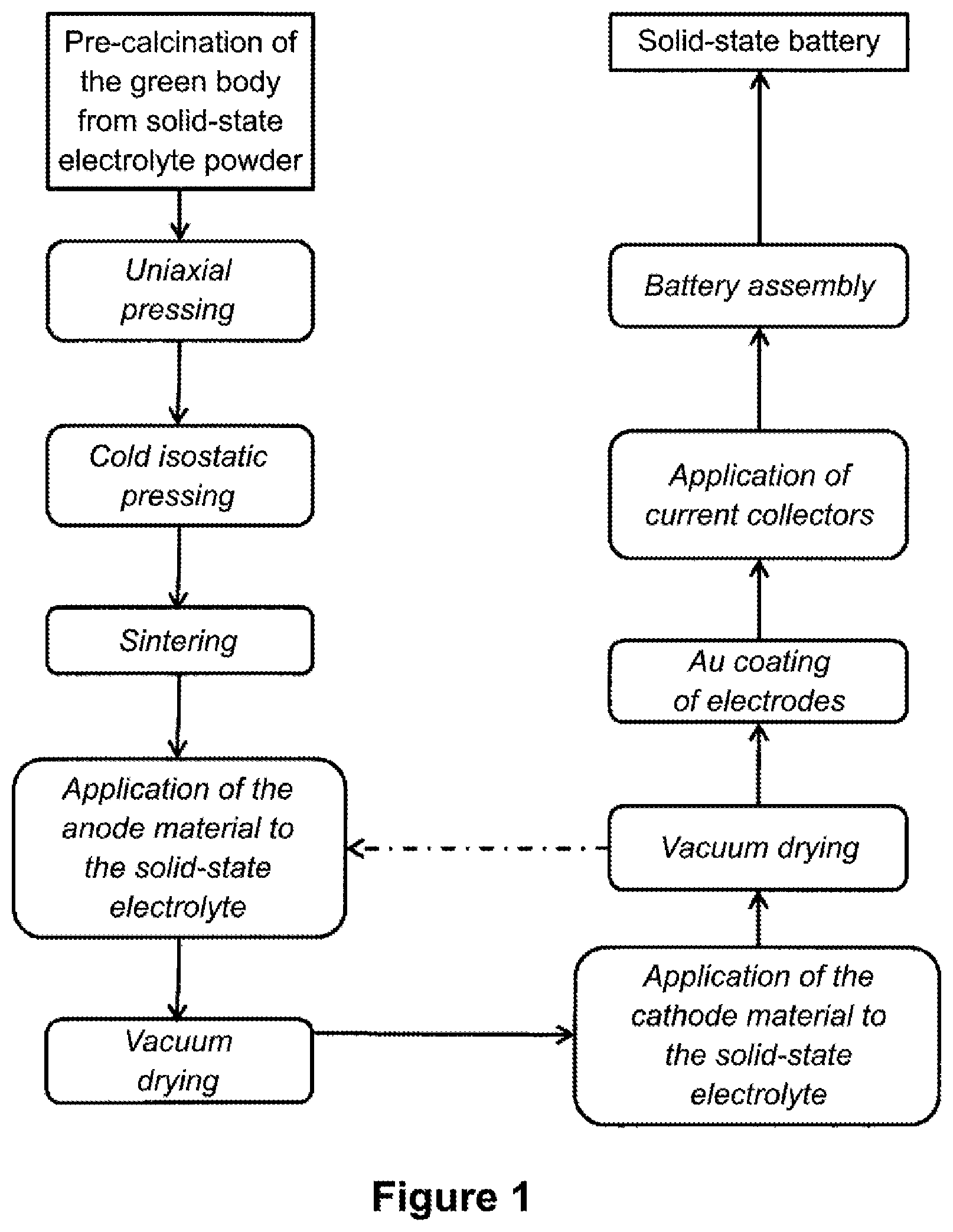
[0018] FIG. 1 is a flowchart of an advantageous embodiment of the electrolyte-based method according to an embodiment of the invention for preparing a solid-state battery;
[0019] FIG. 2 is a flowchart of an electrolyte-based method according to an embodiment of the invention for preparing a solid-state battery having intermediate layers; and
[0020] FIGS. 3a and 3b illustrate, schematically, a structure of solid-state accumulators according to embodiments of the invention, without (FIG. 3a) and with (FIG. 3b) optional intermediate layers having current collectors (1), an anode (2), a solid-state electrolyte (3) according to an embodiment of the invention, a cathode (4), an electrical contact (5), and an accumulator housing (6). Additionally shown in FIG. 3b is an anodic intermediate layer (7) and cathodic intermediate layer (8).
DETAILED DESCRIPTION
[0021] It has been found that, due to the use of different anions in the individual cell components, the contacts at the interfaces between the solid electrodes and the solid electrolyte are often not optimally designed, since the volume expansion of intercalation materials depends upon the respective anion structure of the materials.
[0022] Furthermore, the different expansions during charging and discharging of solid-state accumulators often results, disadvantageously, in the loss of contact between the electrode layers.
[0023] Embodiments of the invention provide effective and economical lithium-ion solid-state accumulators which overcome certain disadvantages known from the prior art.
[0024] Further embodiments of the invention provide simple and cost-effective methods for producing such solid-state accumulators, and in particular, lithium-ion solid-state accumulators.
[0025] Within the scope of the invention, it has been found that the production of a solid-state accumulator, and, particularly, the production of a lithium-ion solid-state accumulator, can advantageously be based upon a solid electrolyte, and not upon one of the electrode sides. The solid-state electrolyte thus assumes the mechanical load-bearing role in the production of the electrochemical cell.
[0026] This means that the construction of the solid-state accumulator produced according to embodiments of the invention takes place on the electrolyte side, i.e., beginning with the production of an almost densely sintered electrolyte, on which, subsequently, the two electrodes can be arranged on the both sides.
[0027] In the following, the term "accumulator" is used for rechargeable batteries.
[0028] According to the invention, it is provided that, first corresponding powder material be pressed into a dense electrolyte layer and then sintered. An electrolyte is then present as an almost densely sintered electrolyte. "Almost densely" is to be understood as meaning that the electrolyte has a density greater than 85% of the theoretical density. At the same time, the electrolyte should have a porosity of not more than 20 vol %--preferably, not more than 15 vol %. In order to have the necessary mechanical stability, the electrolyte layer according to the invention has a layer thickness of at least 100 .mu.m.
[0029] An electrolyte according to the invention can thereby be prepared both via liquid phase synthesis (sol gel or hydrothermal) and via a so-called solid oxide synthesis. In the solid oxide synthesis, the oxidic precursors are ground thoroughly, and subsequently calcined. The electrolyte is then pre-pressed uniaxially in the form of an electrolyte pellet at greater than 10 kN, and then isostatically compressed at greater than 1,200 kN and sintered.
[0030] Electrolyte powders suitable for this purpose comprise, on the one hand, compounds such as oxides, phosphates or even silicates, but, on the other, also phosphorus sulfides. These compounds or phosphorus sulfides, individually, as well as mixtures of various such compounds or phosphorus sulfides, can be used.
[0031] Some specific compounds which are suitable as electrolyte powders in the above sense are listed below by way of example, without being limited to these: [0032] Oxides such as Li.sub.7-xLa.sub.3Zr.sub.2Al.sub.xO.sub.12, where x=0 to 0.5, or Li.sub.7La.sub.3Zr.sub.2-xTa.sub.xO.sub.12, where x=0 to 0.5, [0033] Lithium aluminum titanium phosphates, such as Li.sub.1+xM.sub.xTi.sub.2-x(PO.sub.4).sub.3, where x=0 to 7 and M=Al (LATP), Fe, Y, or Ge, [0034] Lithium lanthanum zirconate, wherein dopings of tantalum, aluminum, and iron can additionally be used, [0035] Lithium phosphorus sulfides, wherein germanium and selenium can be doped, such as Li.sub.7P.sub.3S.sub.11, Li.sub.10P.sub.3S.sub.12, Li.sub.10M.sub.xP.sub.3-xS.sub.12, where M=Ge, Se and x=0 to 1, where M=A.sub.yB.sub.z, wherein A=Si, Ge and B=Sn, Si, and where y=0 to 0.5 and z=1-y.
[0036] In a preferred embodiment of the invention, a mixture of different phosphate compounds is preferably used in the method according to the invention.
[0037] A particularly advantageous powder mixture for the preparation of the solid electrolyte according to the invention comprises, for example, lithium vanadium phosphate (LVP), lithium aluminum titanium phosphate (LATP), and lithium titanium phosphate (LTP). Since it represents the actual ion-conducting electrolyte material, LATP is present in excess and is generally also added to both the anode and the cathode in order to achieve better conductivities.
[0038] The ratio of LVP to LTP in this preferred electrolyte powder is 1.2:1, for example. It is a cathodically-limited cell in which the cathode has more lithium as the active component than the anode can take up.
[0039] The powder for the production of the solid-state electrolyte should have an average particle size between 100 nm and 800 nm--preferably, between 200 nm and 650 nm--in order to allow a density of at least 85% of the theoretical density after compacting and sintering.
[0040] A bimodal or broad distribution of the grain sizes of the electrolyte powder used over the aforementioned relevant range has proven to be advantageous and promising for achieving high theoretical densities. Too-low densities are less conducive to a solid-state electrolyte, since the factor limiting ionic conduction is the grain boundary conductivity.
[0041] The mean grain size (d.sub.50) of the powder used was determined, on the one hand, by means of a scanning electron microscope (SEM) and, on the other, also by the method of measuring the static light scattering.
[0042] By a suitable selection of the powder compounds or mixtures of these compounds for the electrolyte, it is, advantageously, possible to exploit the stability window of the electrolyte or to adapt the overall structure of the accumulator as best as possible to the electrolyte.
[0043] As a specific example of this, the combination LTP and LVP can be mentioned, which exploits the electrochemical stability window of the electrolyte in a particular way. In this case, however, a relatively low cell voltage occurs as a disadvantage, since the voltage of the anode (LTP) against Li/Li.sup.+ is 2.5 V, and thus the high voltage of the cathode cannot be used regularly to achieve high energy densities.
[0044] The solid-state electrolyte prepared in this way preferably has, after a sintering step, a layer thickness between 100 .mu.m and 800 .mu.m--preferably, between 200 .mu.m and 500 .mu.m and, particularly advantageously, between 200 .mu.m and 300 .mu.m. Layer thicknesses of greater than 500 .mu.m can already lead to a limitation of the internal resistance of the cell. The lower limit of 100 .mu.m regularly indicates the lower limit at which the layer can be present in its function as a mechanically-stable carrier.
[0045] In a further step, individual electrode layers can be applied directly on both sides to the previously-sintered electrolyte layer. Screen printing is to be mentioned, in particular, as a suitable method for this purpose. In general, all printing methods, such as offset, roll-to-roll, dipping bed, or ink jet printing are suitable for the system.
[0046] All standard electrode materials can thereby be used, wherein the electrode material used should align itself with the stability window of the electrolyte.
[0047] Examples of suitable oxidic electrode materials for the cathode are:
[0048] LiNiCoAlO.sub.2, LiNiCoMnO.sub.2 (NMC), LiMn.sub.2-xM.sub.xO.sub.4, where M=Ni, Fe, Co, or Ru and where x=0 to 0.5, and LiCoO.sub.2 (LCO).
[0049] The following materials are, for example, suitable as an anode:
[0050] V.sub.2O.sub.5, LiVO.sub.3, Li.sub.3VO.sub.4, and Li.sub.4Ti.sub.5O.sub.12 (LTP).
[0051] Compounds comprising phosphates are also suitable as electrode materials, such as Li.sub.3V.sub.2(PO.sub.4).sub.3 or LiMPO.sub.4, where M=1/4 (Fe, Co, Ni, Mn), for a cathode, or LiM.sub.2(PO.sub.4).sub.3, where M=Zr, Ti, Hf, or a mixture of the same, for an anode.
[0052] As a particular feature, accumulators prepared according to embodiments of the invention have the uniform structure of the polyanions (PO.sub.4).sup.3- across anode, electrolyte, and cathode. This structural feature also occurs when phosphates, phosphorus sulfides, and silicates are used.
[0053] The stability of the solid-state accumulators prepared according to embodiments of the invention is achieved, in particular, by compounds that match structurally, i.e., in their molecular structure. The structural integrity of the system is ensured by an electrode and electrolyte combination, which are matched in their crystal structure and volume expansion.
[0054] An advantageous embodiment of the invention provides that at least one interface between an electrode and the previously prepared solid electrolyte be, in addition, adapted to a particular degree by a micro- and/or nanostructuring.
[0055] In order, for example, to achieve even better structural adaptation of both electrodes to the electrolyte, composite layers of electrolyte and anode material or electrolyte and cathode material can be optionally used as "adhesion-promoting" layers. In these layers, in addition to the pure electrolyte material, nanostructured anode or cathode particles are also included as active components.
[0056] The intermediate layers are generally applied to the solid-state electrolyte with layer thicknesses of between 1 and 10 .mu.m and, particularly, between 1 and 5 .mu.m. Subsequently, the corresponding electrode layers are applied.
[0057] The nanostructuring can be achieved, for example, by the use of solvothermal synthesis with the addition of suitable surfactants, e.g., Triton X100.RTM.. As a result, a compensation of the intrinsic roughness and a good connection of the materials of both layers to each other can be ensured.
[0058] The processing of all further layers of the solid-state accumulator, i.e., the electrode layers and the optional intermediate layers, can, advantageously, be done with standard printing processes, such as screen printing, offset printing, or inkjet.
[0059] An exemplary embodiment of a preparation of a solid-state electrolyte according to an embodiment of the invention and coating thereof are described herein below.
[0060] Pre-calcined lithium aluminum titanium phosphate (LATP) powder is compacted after milling in a ball mill (mean grain size after milling, d.sub.50<1 .mu.m) in a uniaxial piston press into a pellet of 11 mm diameter (40 kN).
[0061] Subsequently, the pellet is polished on the surface and sintered at 1,100.degree. C. (heating rate 2 K/min), holding time for 30 h in the powder bed. The sintered electrolyte pellet has a density of about 90% of the theoretical density and a thickness of about 400 .mu.m. In the process, the diameter shrinks only minimally to about 11.5 mm.
[0062] To prepare the pastes for the electrodes, LVP (for a cathode) or LTP (for an anode), and LATP, carbon powder (Super-P.RTM.), and ethyl cellulose are stirred together in a mortar and then mixed with NMP (1-methyl-pyrrolidone) in a ratio of 9:5:3:3 (wt %) in a tumble mixer for 30 min. These pastes are printed by screen printing with wet layer thicknesses of 70 .mu.m per layer in layers onto the electrolyte pellets. Between the coatings, the pellet is dried overnight in the vacuum at 110.degree. C.
[0063] The dried anode layer has a layer thickness of 60 .mu.m (corresponds to three coatings) for balancing the capacitances, and the cathode layer has a thickness of 90 .mu.m (corresponds to five coatings). The accumulator is subsequently measured in a battery housing under a contact pressure of about 1 t.
[0064] While the invention has been illustrated and described in detail in the drawings and foregoing description, such illustration and description are to be considered illustrative or exemplary and not restrictive. It will be understood that changes and modifications may be made by those of ordinary skill within the scope of the following claims. In particular, the present invention covers further embodiments with any combination of features from different embodiments described above and below.
[0065] The terms used in the claims should be construed to have the broadest reasonable interpretation consistent with the foregoing description. For example, the use of the article "a" or "the" in introducing an element should not be interpreted as being exclusive of a plurality of elements. Likewise, the recitation of "or" should be interpreted as being inclusive, such that the recitation of "A or B" is not exclusive of "A and B," unless it is clear from the context or the foregoing description that only one of A and B is intended. Further, the recitation of "at least one of A, B and C" should be interpreted as one or more of a group of elements consisting of A, B and C, and should not be interpreted as requiring at least one of each of the listed elements A, B and C, regardless of whether A, B and C are related as categories or otherwise. Moreover, the recitation of "A, B and/or C" or "at least one of A, B or C" should be interpreted as including any singular entity from the listed elements, e.g., A, any subset from the listed elements, e.g., A and B, or the entire list of elements A, B and C.
* * * * *
D00000
D00001
D00002
D00003
XML
uspto.report is an independent third-party trademark research tool that is not affiliated, endorsed, or sponsored by the United States Patent and Trademark Office (USPTO) or any other governmental organization. The information provided by uspto.report is based on publicly available data at the time of writing and is intended for informational purposes only.
While we strive to provide accurate and up-to-date information, we do not guarantee the accuracy, completeness, reliability, or suitability of the information displayed on this site. The use of this site is at your own risk. Any reliance you place on such information is therefore strictly at your own risk.
All official trademark data, including owner information, should be verified by visiting the official USPTO website at www.uspto.gov. This site is not intended to replace professional legal advice and should not be used as a substitute for consulting with a legal professional who is knowledgeable about trademark law.