Nondestructive Inspection Using Dual Pulse-echo Ultrasonics And Method Therefor
Finn; Alan Matthew ; et al.
U.S. patent application number 15/971270 was filed with the patent office on 2019-11-07 for nondestructive inspection using dual pulse-echo ultrasonics and method therefor. This patent application is currently assigned to United Technologies Corporation. The applicant listed for this patent is United Technologies Corporation. Invention is credited to Edgar A. Bernal, Ozgur Erdinc, Alan Matthew Finn, Amit Surana, Matthew O. Williams.
| Application Number | 20190339234 15/971270 |
| Document ID | / |
| Family ID | 68385063 |
| Filed Date | 2019-11-07 |


| United States Patent Application | 20190339234 |
| Kind Code | A1 |
| Finn; Alan Matthew ; et al. | November 7, 2019 |
NONDESTRUCTIVE INSPECTION USING DUAL PULSE-ECHO ULTRASONICS AND METHOD THEREFOR
Abstract
A method for nondestructive inspection of a component, the method includes determining a first pulse-echo scan from a first side of a component; determining a second pulse-echo scan from a second side of the component; determining a through-transmission scan based on the, first pulse-echo scan, the second pulse-echo scan, and a model of the component, the model comprises a rigid internal structure of the component; and classifying the component based on comparing the through-transmission scan to a "gold" model.
| Inventors: | Finn; Alan Matthew; (Hebron, CT) ; Surana; Amit; (West Hartford, CT) ; Williams; Matthew O.; (Honolulu, HI) ; Bernal; Edgar A.; (Webster, NY) ; Erdinc; Ozgur; (Mansfield, CT) | ||||||||||
| Applicant: |
|
||||||||||
|---|---|---|---|---|---|---|---|---|---|---|---|
| Assignee: | United Technologies
Corporation Farmington CT |
||||||||||
| Family ID: | 68385063 | ||||||||||
| Appl. No.: | 15/971270 | ||||||||||
| Filed: | May 4, 2018 |
| Current U.S. Class: | 1/1 |
| Current CPC Class: | G01N 29/225 20130101; G01N 29/265 20130101; G01N 2291/2694 20130101; G01N 29/44 20130101; G01N 2291/048 20130101; G01N 29/26 20130101; G01N 2291/10 20130101; G01N 2291/0231 20130101; G01N 2291/044 20130101; G01N 29/4418 20130101; G01N 29/11 20130101; G01N 29/0654 20130101; G01N 29/043 20130101; G01N 2291/0289 20130101; G01N 2291/051 20130101 |
| International Class: | G01N 29/26 20060101 G01N029/26; G01N 29/11 20060101 G01N029/11; G01N 29/44 20060101 G01N029/44 |
Claims
1. A method for nondestructive inspection of a component, the method comprising: determining a first pulse-echo scan from a first side of a component; determining a second pulse-echo scan from a second side of the component; comparing the first pulse-echo scan to a first model from the first side of the component, the first model comprises a rigid internal structure of the component; comparing the second pulse-echo scan to a second model from the second side of the component, the second model comprises the rigid internal structure of the component; and classifying the component based on the comparing.
2. The method as recited in claim 1, further comprising guiding a first pulse echo ultrasonic transducer in accords with the first model and a second pulse echo ultrasonic transducer in accords with the second model.
3. The method as recited in claim 2, wherein the guiding comprises identifying a defect only within a predetermined area.
4. The method as recited in claim 2, further comprising determining a defect in response to at least one of a difference between the first through-transmission scan and a first gold model and a difference between the second through-transmission scan and a second gold model.
5. The method as recited in claim 2, wherein the guiding aligns the first pulse-echo ultrasonic transducer and the second pulse-echo ultrasonic transducer along a path of maximum energy transmission.
6. The method as recited in claim 3, wherein the guiding comprises defining a predetermined area adjacent the rigid internal structure of the component.
7. The method as recited in claim 5, wherein the defining the predetermined area is associated with a side of the component.
8. The method as recited in claim 1, wherein classifying the component comprises identifying a delamination area.
9. The method as recited in claim 1, further comprising at least one of a through-transmission scan from the first side of the component to the second side of the component using the first model; and a through-transmission scan from the second side of the component to the first side of the component using the second model.
10. A method for nondestructive inspection of a component, the method comprising: guiding a first pulse echo ultrasonic transducer in accords with a first model of a component and a second pulse echo ultrasonic transducer in accords with a second model of the component; determining a first pulse-echo scan from a first side of a component; determining a second pulse-echo scan from a second side of the component; and identifying a defect only from within a predetermined area of the component based on the first model and the second model.
11. The method as recited in claim 10, wherein the predetermined area is an area that includes a rigid internal structure.
12. The method as recited in claim 10, wherein identifying the defect comprises: comparing the first pulse-echo scan to the first model from the first side of the component; and comparing the second pulse-echo scan to the second model from the second side of the component
13. The method as recited in claim 10, wherein identifying the defect comprises: determining a difference between the first pulse-echo scan to a first gold model; and determining a difference between the second pulse-echo scan to a second gold model.
14. The method as recited in claim 10, further comprising orienting the first model and the second model with respect to the component based on an edge of the model and an edge of the component.
15. The method as recited in claim 10, wherein the first model and the second model are at least one of an as-designed model, an as-built model, and a previous condition model.
16. A nondestructive inspection system to inspect a component, the system comprising: a first pulse echo ultrasonic transducer to provide a first pulse-echo scan from a first side of a component, the first pulse echo ultrasonic transducer operable to receive a through-transmission from the second pulse echo ultrasonic transducer; a second pulse echo ultrasonic transducer to provide a second pulse-echo scan from a second side of the component, the second pulse echo ultrasonic transducer operable to receive a through-transmission from the first pulse echo ultrasonic transducer; and a controller in communication with the first pulse echo ultrasonic transducer and the second pulse echo ultrasonic transducer, the controller operable to identify a defect within a predetermined area of the component based on at least one of a difference between the first through-transmission scan and a first gold model and a difference between the second through-transmission scan and a second gold model.
17. The system as recited in claim 16, further comprising a database, the database identifies a location of an internal structure of the component from a perspective of the component associated with the first model and the second model.
18. The system as recited in claim 16, wherein the first model and the second model are at least one of an as-designed model, an as-built model, and a previous condition model.
19. The system as recited in claim 16, further comprising a first position control to position the first pulse echo ultrasonic transducer guided by the controller in response to the first model, and a second position control to position the second pulse echo ultrasonic transducer guided by the controller in response to the second model.
Description
BACKGROUND
[0001] The present disclosure relates to nondestructive component inspection and, more particularly, to a nondestructive ultrasonic damage detection system for prognostics and health management, preventative maintenance, and repair of engine components.
[0002] Manufactured components may incur defects or imperfections during manufacturing or suffer wear and damage during operation. These components, therefore, are episodically or periodically inspected for defects and damage. One particular form of imperfection or damage consists of a "kissing bond" (also referred to as a zero-volume disbond) which is an interfacial or interstitial defect within a bond of a composite structure which shows no sign of separation at the interface. The defect is such that the opposing surfaces are substantially in contact with one another but are not bonded together. This may happen, for instance, when an adhesive begins to cure ("skins over") before the parts are mated. An interstitial defect in the adhesive greatly decreases the strength of the bond.
[0003] Traditional ultrasonic pulse echo (one-sided) techniques do not reliably detect kissing bonds because there is limited impedance mismatch (limited reflection coefficient) across the disbond. Ultrasonic through-transmission (two-sided) techniques are preferred since the attenuation across the disbond will produce a locally different, disbond-dependent, transmitted energy. This difference is typically small and relatively difficult to detect. The detection of the local difference may be improved by differential signal processing, by computing a difference between an expected energy, typically based on prior experimentation or a physics-based model, and the received energy. In the case of a proper bond, the difference is effectively zero; in the case of a disbond, the difference is non-zero.
[0004] The traditional through-transmission technique aligns a transmitter on one side of a component under inspection and receiver opposite the transmitter on the other side along a common axis orthogonal to the component. This technique effectively ignores the actual acoustic path through any internal structure of the component. In particular, when the internal structure is not orthogonal to the surface, the receiver may not be aimed at the emergence location of the transmitted sound energy.
SUMMARY
[0005] A method for nondestructive inspection of a component, the method according to one disclosed non-limiting embodiment of the present disclosure includes determining a first pulse-echo scan from a first side of a component; determining a second pulse-echo scan from a second side of the component; comparing the first pulse-echo scan to a first model from the first side of the component, the first model comprises a rigid internal structure of the component; comparing the second pulse-echo scan to a second model from the second side of the component, the second model comprises the rigid internal structure of the component; and classifying the component based on the comparing.
[0006] A further aspect of the present disclosure includes guiding a first pulse echo ultrasonic transducer in accords with the first model and a second pulse echo ultrasonic transducer in accords with the second model.
[0007] A further aspect of the present disclosure includes that the guiding comprises identifying a defect only within a predetermined area.
[0008] A further aspect of the present disclosure includes determining a defect in response to at least one of a difference between the first through-transmission scan and a first gold model and a difference between the second through-transmission scan and a second gold model.
[0009] A further aspect of the present disclosure includes that the guiding aligns the first pulse-echo ultrasonic transducer and the second pulse-echo ultrasonic transducer along a path of maximum energy transmission.
[0010] A further aspect of the present disclosure includes that the guiding comprises defining a predetermined area adjacent the rigid internal structure of the component.
[0011] A further aspect of the present disclosure includes that the defining the predetermined area is associated with a side of the component.
[0012] A further aspect of the present disclosure includes that classifying the component comprises identifying a delamination area.
[0013] A further aspect of the present disclosure includes at least one of a through-transmission scan from the first side of the component to the second side of the component using the first model; and a through-transmission scan from the second side of the component to the first side of the component using the second model.
[0014] A method for nondestructive inspection of a component, the method according to one disclosed non-limiting embodiment of the present disclosure includes guiding a first pulse echo ultrasonic transducer in accords with a first model of a component and a second pulse echo ultrasonic transducer in accords with a second model of the component; determining a first pulse-echo scan from a first side of a component; determining a second pulse-echo scan from a second side of the component; and identifying a defect only from within a predetermined area of the component based on the first model and the second model.
[0015] A further aspect of the present disclosure includes that the predetermined area is an area that includes a rigid internal structure.
[0016] A further aspect of the present disclosure includes comparing the first pulse-echo scan to the first model from the first side of the component; and comparing the second pulse-echo scan to the second model from the second side of the component.
[0017] A further aspect of the present disclosure includes determining a difference between the first pulse-echo scan to a first gold model; and determining a difference between the second pulse-echo scan to a second gold model.
[0018] A further aspect of the present disclosure includes orienting the first model and the second model with respect to the component based on an edge of the model and an edge of the component.
[0019] A further aspect of the present disclosure includes that the first model and the second model are at least one of an as-designed model, an as-built model, and a previous condition model.
[0020] A nondestructive inspection system to inspect a component, the system according to one disclosed non-limiting embodiment of the present disclosure includes a first pulse echo ultrasonic transducer to provide a first pulse-echo scan from a first side of a component, the first pulse echo ultrasonic transducer operable to receive a through-transmission from the second pulse echo ultrasonic transducer; a second pulse echo ultrasonic transducer to provide a second pulse-echo scan from a second side of the component, the second pulse echo ultrasonic transducer operable to receive a through-transmission from the first pulse echo ultrasonic transducer; and a controller in communication with the first pulse echo ultrasonic transducer and the second pulse echo ultrasonic transducer, the controller operable to identify a defect within a predetermined area of the component based on at least one of a difference between the first through-transmission scan and a first gold model and a difference between the second through-transmission scan and a second gold model.
[0021] A further aspect of the present disclosure includes a database, the database identifies a location of an internal structure of the component from a perspective of the component associated with the first model and the second model.
[0022] A further aspect of the present disclosure includes wherein the first model and the second model are at least one of an as-designed model, an as-built model, and a previous condition model.
[0023] A further aspect of the present disclosure includes a first position control to position the first pulse echo ultrasonic transducer guided by the controller in response to the first model, and a second position control to position the second pulse echo ultrasonic transducer guided by the controller in response to the second model.
[0024] The foregoing features and elements may be combined in various combinations without exclusivity, unless expressly indicated otherwise. These features and elements as well as the operation thereof will become more apparent in light of the following description and the accompanying drawings. It should be understood, however, the following description and drawings are intended to be exemplary in nature and non-limiting.
BRIEF DESCRIPTION OF THE DRAWINGS
[0025] Various features will become apparent to those skilled in the art from the following detailed description of the disclosed non-limiting embodiments. The drawings that accompany the detailed description can be briefly described as follows:
[0026] FIG. 1 is a schematic view of a nondestructive ultrasonic damage detection system.
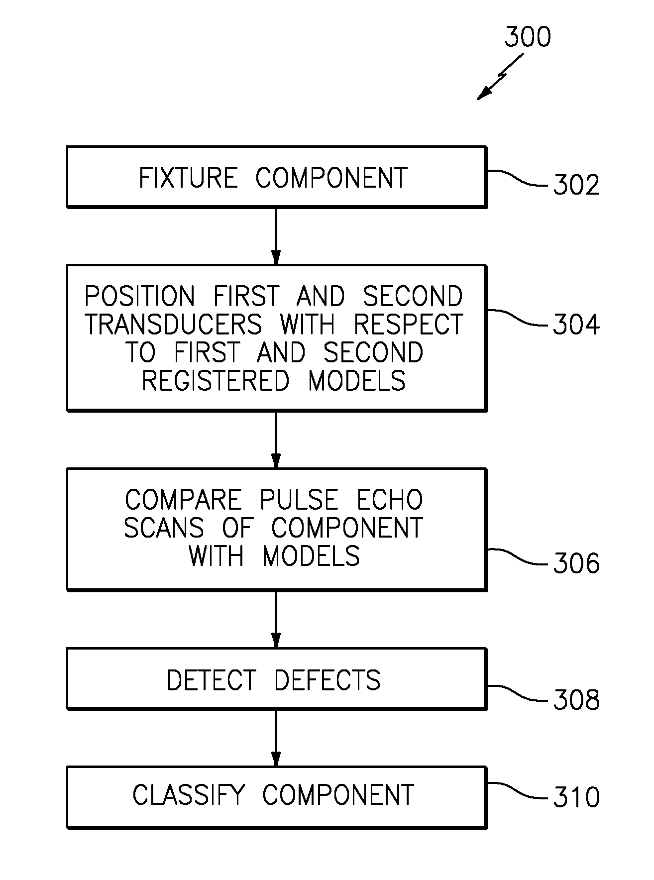
[0027] FIG. 2 is a block diagram representing a method of inspection using the nondestructive ultrasonic damage detection system.
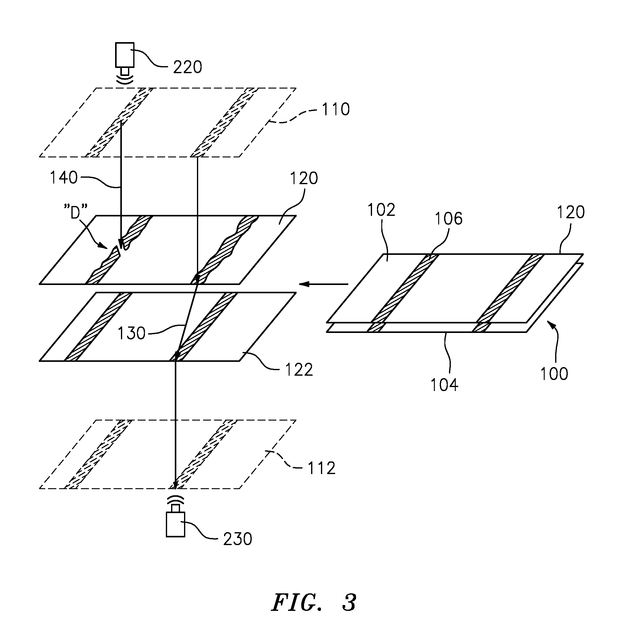
[0028] FIG. 3 is a representation of the method of inspection.
DETAILED DESCRIPTION
[0029] FIG. 1 schematically illustrates a nondestructive ultrasonic damage detection system 200. The system 200 utilizes models of internal component structure to guide the detection, computation of shape features, and classification of defects based on those shape features. The techniques are particularly applicable to composite material manufacturing defects such as disbonding or delamination within a component 100. The component 100, for example a fan blade of a gas turbine engine, may have a substrate 102, a cover 104, and a rigid internal structure 106. In this example, the cover 104 is bonded to the internal structure 106 which, in turn, is either bonded to, or is an integral part of, the substrate 102. While this disclosure is taught with respect to a fan blade, it is explicitly contemplated that the teaching herein is applicable to both natural and manufactured composite objects with internal structure.
[0030] The nondestructive ultrasonic damage detection system 200 includes a fixture 210 to retain the component 100, a first pulse echo ultrasonic transducer 220, a first position control 222 to position the first pulse echo ultrasonic transducer 220, a second pulse echo ultrasonic transducer 230, a second position control 232 to position the second pulse echo ultrasonic transducer 230, and a control system 250. The first and second pulse echo ultrasonic transducers 220, 230 transmit short-duration ultrasound pulses into the region to be studied, and echo signals resulting from scattering and reflection are detected and may be processed and displayed. Pulse echo ultrasonic transducers 220, 230, respectively, may also receive through-transmission ultrasonic pulses from pulse echo ultrasonic transducers 230, 220, respectively. Since an ultrasonic transmitter is also effectively an ultrasonic receiver, no additional hardware is needed for pulse echo ultrasonic transducers 220, 230 to operate as bi-directional through-transmission hardware.
[0031] The first and second position control 222, 232 may be a computer numerical control (CNC) robotic manipulator system that moves the first and second pulse echo ultrasonic transducer 220, 230 in response to the control system 250. The control system 250 may include hardware, firmware, and/or software components that are configured to perform the functions disclosed herein, including the operation of the first and second positon control 222, 232. While not specifically shown, the control system 250 may include other computing devices (e.g., servers, mobile computing devices, and the like) and computer aided manufacturer (CAM) systems which may be in communication with each other and/or the control system 250 via a communication network to perform one or more of the disclosed functions. The control system 250 may include at least one processor 252 (e.g., a controller, microprocessor, microcontroller, digital signal processor, and the like), memory 254, and an input/output (I/O) subsystem 256. The control system 250 may be embodied as any type of computing device (e.g., a workstation, an embedded computer, an FPGA, a tablet computer, smart phone, body-mounted device or wearable device, and the like, a server, an enterprise computer system, a network of computers, a combination of computers and other electronic devices, or other electronic devices). Although not specifically shown, the I/O subsystem 256 typically includes, for example, an I/O controller, a memory controller, and one or more I/O ports. The processor 252 and the I/O subsystem 256 are communicatively coupled to the memory 254. The memory 254 may be embodied as any type of computer memory device (e.g., volatile memory such as various forms of random access memory).
[0032] The I/O subsystem 256 may also be communicatively coupled to a number of hardware, firmware, and/or software components, including a data storage device 258, a display 260, and a user interface (UI) subsystem 262. The data storage device 258 may include one or more hard drives or other suitable persistent storage devices (e.g., flash memory, memory cards, memory sticks, and/or others). A database 270 for models of the component may reside at least temporarily in the data storage device 258 and/or other data storage devices (e.g., data storage devices that are "in the cloud" or otherwise connected to the control system 250 by a network). The models of the component 100 may be an as-designed model, an as-built model, a previous condition model, and the like
[0033] With reference to FIGS. 2 and 3, one disclosed non-limiting embodiment of a method 300 for nondestructive component inspection initially includes locating the component in the fixture 210 of the system 200 (step 302). Although a fan blade of a gas turbine engine is illustrated as the representative example component, any such composite component can be inspected by the system 200.
[0034] Next, the first positon control 222 positons the first pulse echo ultrasonic transducer 220 to determine a first pulse-echo scan 120 from a first side of the component 100 and a second positon control 232 positons the second pulse echo ultrasonic transducer 230 from a second side of the component 100. The first and second positon control 222, 232 move the respective first and second pulse echo ultrasonic transducer 220, 230 guided by the control system 250 in response to a first registration model 110 of the first side of the component and a second registration model 112 of the second side of the component. The models 110, 112 include the rigid internal structure 106 such that predetermined areas can be delineated in association therewith. That is, the predetermined areas identify the location of the rigid internal structure 106 from the associated sides of the component 100 to isolate particular areas which both transmit ultrasonic energy and may be subject to defects such as disbonding and/or delamination.
[0035] The internal structure 106 is registered via one or more models 110, 112 of the component 100. Multiple models may be required since the rigid internal structure 106 on one side of component 100 need not be directly aligned with the rigid internal structure 106 on the other side of component 110. The registered structural models to both front and back pulse-echo images allow guidance of the first and second pulse echo ultrasonic transducer 220, 230 and reasoning about expected through-transmission acoustic energy for defect detection.
[0036] The models may be an as-designed model, an as-built model, a previous condition model, and the like. The registration may make use of edges of the composite component 100 to scale, rotate, and or translate the model to elucidate the internal structure 106 from the perspective of the first and second pulse echo ultrasonic transducer 220, 230 for automated reasoning about the predetermined areas at which a defect may occur. That is, the registered models may be used to constrain detection of defects in the pulse-echo scans 120, 122 or the corresponding through-transmission scans (one direction shown: 130, 140) to only the predetermined areas. The registered models may also be used to guide the first and second pulse echo ultrasonic transducer 220, 230 since, for efficient inspection speed, only the predetermined areas adjacent to the rigid internal structure 106 may need to be scanned.
[0037] The predetermined areas with the rigid internal structure 106 from the models are used to influence the detection of damage, particularly where the damage manifests as a `distorted pattern` in the pulse-echo or through-transmission scan. This influencing of the detection of damage may be based on, for example, the known internal structure, as initialization of an active contour shape determination, a geometric restriction for the predetermined area over which statistical characterization is performed, as priors in a Bayesian estimation, or other technique that limits portions of the pulse-echo scan. For example, a disbond may be detected because it appears at a particular location with respect to the known location of the rigid internal structure 106 where the identical pulse-echo scan imagery that is not at a known location of the rigid internal structure 106 may be ignored.
[0038] The through-transmission excitation is largely carried by the rigid internal structure 106 and, by using the models 110, 112, the expected energy transmission may be compared to the actual energy transmission for the detection of defects as represented by the interrupted energy path "D" in the through-transmission scan 140 due to a defect.
[0039] The pulse-echo scan 120 of the first side of the component produces pulse-echo scan imagery substantially representing the top of the internal structure 106. Likewise, the pulse-echo scan 122 of the back of the component 100 produces an image substantially representing the bottom of the internal structure 106. The models 110, 112 of the top (bottom) structure may be registered to the respective top (bottom) pulse-echo scan imagery using, for instance, a random consensus (RANSAC) algorithm based on computed features where the features may include SIFT, SURF, ASIFT, other SIFT variants, Harris Corner features, SUSAN, FAST, a Phase Correlation, a Normalized Cross-Correlation, GLOH, BRIEF, CenSure/STAR, ORB, and the like. Alternatively, or in addition, the models 110, 112 may be used to separately guide an acoustically-aligned through-transmission scan (one direction shown: 130, 140) where the transducers are aligned along the acoustic transmission path rather than being simply opposite each other along an axis orthogonal to the component.
[0040] The pulse-echo or through-transmission scans may be normalized and compared (step 306) with the models in the database 270 to initialize or constrain detection of damage in the pulse-echo or through-transmission scan features to only the relevant area or shape. The pulse-echo or through-transmission scans of the subject component may be normalized to account for overall differences in excitation energy, different gain in the transmitter or receiver, and the like.
[0041] In order to correctly interpret the pulse-echo or through-transmission scan imagery, both the internal structure 106 and how any defects (step 308) may manifest are guided by the models 110, 112. In embodiments, the pulse-echo scans are used for guidance, while through-transmission may be used for damage detection. Alternatively, pulse-echo may be used for damage detection. In embodiments, the detection of defects may use a difference between the through-transmission of the subject component and a "gold model" scan derived from previous experimentation, an expected energy model derived from the physics of acoustic transmission, and the like. In one example, the gold model may be derived from the through-transmission data. For example, the gold model may be those data values within a predetermined number of standard deviations from the mean of the data values. The difference may be analyzed by a statistical detector (hypothesis detector) where one hypothesis is that the differential energy is zero and the other hypothesis is that the differential energy is non-zero.
[0042] In another embodiment, other statistical detection or regression techniques may be employed such as principal components analysis (PCA), robust PCA (RPCA), support vector machines (SVM), linear discriminant analysis (LDA), expectation maximization (EM), Boosting, Dictionary Matching, maximum likelihood (ML) estimation, maximum a priori (MAP) estimation, least squares (LS) estimation, non-linear LS (NNLS) estimation, Bayesian Estimation, and the like. Additional morphological filtering may be used to effectively ignore very small detections that may result from noise or that would not significantly affect bond strength and component reliability.
[0043] In yet another embodiment, defects can be detected via a deep learning classifier trained from available data, such as a library of user characterized damage examples stored within the database 270. Deep learning is the process of training or adjusting the weights of a deep neural network. In one example, the deep neural network is a deep convolutional neural network trained by presenting an error map or partial error map to an input layer and a damage/no-damage label to an output layer. The training of a deep convolutional network proceeds layer-wise and does not require a label until the output layer is trained. The weights of the deep network's layers are adapted, typically by a stochastic gradient descent algorithm, to produce a correct classification. The deep learning training may use only partially labeled data, only fully labeled data, or only implicitly labeled data, or may use unlabeled data for initial or partial training with only a final training on labeled data.
[0044] The component may then be classified (step 310) based on the defect determination into binary (e.g. reject, accept) or multi-class categories (e.g., a score), using algorithms such as a logistics regression, nearest neighbor metrics, deep neural networks, Bayesian estimation, support vector machines, decision trees, random forests, and the like.
[0045] The nondestructive ultrasonic damage detection system 200 permits inspection of components to detect defects by registering a model and constraining the analytics based on the model. The nondestructive ultrasonic damage detection system 200 facilitates automated inspection that reduces cost of poor quality (COPQ) from faulty human visual inspection; reduces turn-backs from subsequent inspector disagreement; reduces dependence on increasingly scarce skilled inspectors; reduces inspection time and cost, increases inspector efficiency; and gathers machine-readable data on component condition for repair scheduling, life estimation, (re)design, and training.
[0046] The use of the terms "a", "an", "the", and similar references in the context of description (especially in the context of the following claims) are to be construed to cover both the singular and the plural, unless otherwise indicated herein or specifically contradicted by context. The modifier "about" used in connection with a quantity is inclusive of the stated value and has the meaning dictated by the context (e.g., it includes the degree of error associated with measurement of the particular quantity). All ranges disclosed herein are inclusive of the endpoints, and the endpoints are independently combinable with each other. It should be appreciated that relative positional terms such as "forward", "aft", "upper", "lower", "above", "below", and the like are with reference to normal operational attitude and should not be considered otherwise limiting.
[0047] Although the different non-limiting embodiments have specific illustrated components, the embodiments of this invention are not limited to those particular combinations. It is possible to use some of the components or features from any of the non-limiting embodiments in combination with features or components from any of the other non-limiting embodiments.
[0048] It should be appreciated that like reference numerals identify corresponding or similar elements throughout the several drawings. It should also be appreciated that although a particular component arrangement is disclosed in the illustrated embodiment, other arrangements will benefit herefrom.
[0049] Although particular step sequences are shown, described, and claimed, it should be understood that steps may be performed in any order, separated or combined unless otherwise indicated and will still benefit from the present disclosure.
[0050] The foregoing description is exemplary rather than defined by the limitations within. Various non-limiting embodiments are disclosed herein, however, one of ordinary skill in the art would recognize that various modifications and variations in light of the above teachings will fall within the scope of the appended claims. It is therefore to be understood that within the scope of the appended claims, the disclosure may be practiced other than as specifically described. For that reason, the appended claims should be studied to determine true scope and content.
* * * * *
D00000
D00001
D00002
D00003
XML
uspto.report is an independent third-party trademark research tool that is not affiliated, endorsed, or sponsored by the United States Patent and Trademark Office (USPTO) or any other governmental organization. The information provided by uspto.report is based on publicly available data at the time of writing and is intended for informational purposes only.
While we strive to provide accurate and up-to-date information, we do not guarantee the accuracy, completeness, reliability, or suitability of the information displayed on this site. The use of this site is at your own risk. Any reliance you place on such information is therefore strictly at your own risk.
All official trademark data, including owner information, should be verified by visiting the official USPTO website at www.uspto.gov. This site is not intended to replace professional legal advice and should not be used as a substitute for consulting with a legal professional who is knowledgeable about trademark law.