Method For A Mobile Dimensioning Device To Use A Dynamic Accuracy Compatible With Nist Standard
Laffargue; Franck ; et al.
U.S. patent application number 16/507338 was filed with the patent office on 2019-11-07 for method for a mobile dimensioning device to use a dynamic accuracy compatible with nist standard. The applicant listed for this patent is Hand Held Products, Inc.. Invention is credited to H. Sprague Ackley, Franck Laffargue, Scott McCloskey.
| Application Number | 20190339057 16/507338 |
| Document ID | / |
| Family ID | 53724011 |
| Filed Date | 2019-11-07 |


| United States Patent Application | 20190339057 |
| Kind Code | A1 |
| Laffargue; Franck ; et al. | November 7, 2019 |
METHOD FOR A MOBILE DIMENSIONING DEVICE TO USE A DYNAMIC ACCURACY COMPATIBLE WITH NIST STANDARD
Abstract
A mobile dimensioning device, i.e. a mobile dimensioner, is described that uses a dynamic accuracy while still being compatible with the NIST standard. Even if the accuracy division is dynamic and not predetermined, a mobile dimensioning device of the present invention reports the actual dimensioning prior to measurement capture and can therefore be certified and used in commercial transactions.
| Inventors: | Laffargue; Franck; (Toulouse, FR) ; McCloskey; Scott; (Minneapolis, MN) ; Ackley; H. Sprague; (Seattle, WA) | ||||||||||
| Applicant: |
|
||||||||||
|---|---|---|---|---|---|---|---|---|---|---|---|
| Family ID: | 53724011 | ||||||||||
| Appl. No.: | 16/507338 | ||||||||||
| Filed: | July 10, 2019 |
Related U.S. Patent Documents
| Application Number | Filing Date | Patent Number | ||
|---|---|---|---|---|
| 15146084 | May 4, 2016 | 10393506 | ||
| 16507338 | ||||
| Current U.S. Class: | 1/1 |
| Current CPC Class: | G01B 21/047 20130101; G06F 3/0484 20130101; G06F 3/04817 20130101; G01B 11/02 20130101; G06T 15/08 20130101; G06T 2215/16 20130101 |
| International Class: | G01B 11/02 20060101 G01B011/02; G01B 21/04 20060101 G01B021/04; G06T 15/08 20060101 G06T015/08; G06F 3/0481 20060101 G06F003/0481; G06F 3/0484 20060101 G06F003/0484 |
Foreign Application Data
| Date | Code | Application Number |
|---|---|---|
| Jul 15, 2015 | EP | 15176943.7 |
Claims
1. A mobile dimensioning device, comprising: a display; a non-volatile storage; a sensor; an input subsystem; a processor; and a memory comprising computer-executable instructions that, when executed by the processor, cause the mobile dimensioning device to: derive an accuracy parameter based on information received from the sensor for a measurement environment of an object being measured; compute an accuracy level based on the accuracy parameter; in response to determining that the accuracy level corresponds to a sufficient measurement environment, display, on the display, an acceptance icon to facilitate the display of the accuracy level; and in response to receiving an input associated with the acceptance icon, display, on the display, the accuracy level and a capture icon to facilitate measurement capture.
2. The mobile dimensioning device of claim 1, wherein the accuracy level corresponds to a National Institutes of Standards and Technology (NIST) standard associated with accuracy.
3. The mobile dimensioning device of claim 1, wherein the accuracy parameter is associated with at least one of: a distance to the object, a viewing angle relative to the object, a temperature, ambient light, or a quality of data from the sensor.
4. The mobile dimensioning device of claim 1, wherein the sensor is at least one of: an optical sensor or a measurement sensor.
5. The mobile dimensioning device of claim 4, wherein the optical sensor is at least one of: a barcode sensor, a camera, or an image sensor.
6. The mobile dimensioning device of claim 4, wherein the measurement sensor is at least one of: a point-cloud projection sensor, a structured light sensor, a stereoscopic camera, or an n-scopic camera.
7. The mobile dimensioning device of claim 2, wherein the sufficient measurement environment is an environment where an accuracy division has a value lower than a predetermined value.
8. The mobile dimensioning device of claim 1, wherein the computer-executable instructions, when executed by the processor, cause the mobile dimensioning device to further: display, on the display, an indication that the measurement environment is sufficient, comprising at least one of: displaying an accuracy division, displaying an icon to facilitate capture of dimensions of the object, removing indications for improving the measurement environment, displaying a completed progress bar, or displaying a confirmation icon.
9. The mobile dimensioning device of claim 1, wherein computing the accuracy level based on the accuracy parameter comprises calculating multivariable regression on the accuracy parameter.
10. The mobile dimensioning device of claim 1, wherein the computer-executable instructions, when executed by the processor, cause the mobile dimensioning device to further: in response to determining that the accuracy level does not correspond to the sufficient measurement environment, provide an indication for improving the measurement environment.
11. The mobile dimensioning device of claim 10, wherein the indication for improving the measurement environment comprises at least one of: a textual instruction, a graphical instruction, or a graphical icon.
12. The mobile dimensioning device of claim 10, wherein the indication for improving the measurement environment comprises at least one of: an indication for shortening a distance to the object, an indication for improving a viewing angle relative to the object, an indication to delay measurement pending a target operating temperature, an indication for improving an ambient light, or an indication for adjusting the sensor to improve a quality of data.
13. The mobile dimensioning device of claim 1, wherein the computer-executable instructions, when executed by the processor, cause the mobile dimensioning device to further: in response to an input received associated with the capture icon, capture measurement; display, on the display, dimensions of the object; and record the dimensions of the object.
14. A method for measuring dimensions of an object, comprising: deriving, based on information received from a sensor, an accuracy parameter that is associated with an accuracy level for a measurement environment of the object being measured; computing the accuracy level based on the accuracy parameter; determining if the accuracy level is sufficient for the measurement environment; in response to the accuracy level being not sufficient for the measurement environment; providing an indication for improving the accuracy level of the measurement environment; and in response to the accuracy level being sufficient for the measurement environment; causing a capture icon, configured to facilitate capture of measurement of the dimensions of the object, to be displayed on a display.
15. The method for measuring the dimensions of the object of claim 14, wherein the capture icon is caused to be displayed on the display with an indication that the measurement environment is sufficient.
16. The method for measuring the dimensions of the object of claim 14 further comprises: in response to the accuracy level being sufficient for the measurement environment, displaying, on the display, an acceptance icon to facilitate the display of the accuracy level, wherein the capture icon is caused to be displayed on the display in response to an input received at the acceptance icon.
17. The method for measuring the dimensions of the object of claim 16 further comprises: in response to the accuracy level being sufficient for the measurement environment, causing the accuracy level to be displayed on the display.
18. The method for measuring the dimensions of the object of claim 14, wherein the accuracy parameter is associated with at least one of: a distance to the object, a viewing angle relative to the object, a temperature, ambient light, or a quality of data from the sensor.
19. The method for measuring the dimensions of the object of claim 14 further comprising: in response to the accuracy level being not sufficient for the measurement environment, providing an indication for improving the measurement environment.
20. The method for measuring the dimensions of the object of claim 19, wherein the indication for improving the measurement environment comprises at least one of: a textual instruction, a graphical instruction, or a graphical icon.
Description
CROSS-REFERENCE TO RELATED APPLICATION
[0001] The present application is a continuation application of U.S. application Ser. No. 15/146,084, filed May 4, 2016, which claims the benefit of European Patent Application No. 15176943.7 for a Method for a Mobile Dimensioning Device to Use a Dynamic Accuracy Compatible with NIST Standard filed on Jul. 15, 2015 at the European Patent Office, the contents of which are hereby incorporated by reference in their entireties.
FIELD OF THE INVENTION
[0002] The present invention relates to mobile volume dimensioning devices.
BACKGROUND
[0003] A traditional Multiple Dimensioning Measurement Device (MDMD) captures the three dimensional size (i.e. length, width, height) of objects, such as parcels or pallets, based on the predetermined accuracy of the system. In the United States National Institutes of Standards and Technology (NIST) standard, this predetermined accuracy level of the system is known as the accuracy division.
[0004] Some MDMD devices support operations with different accuracy divisions, but these accuracy divisions are still predetermined. For example, an MDMD can provide a measurement with an accuracy of 1 cm for objects with dimensions smaller than 50 cm and can provide a measurement with an accuracy of 2 cm for objects with dimensions greater than 50 cm.
[0005] Predetermined accuracy divisions work for fixed dimensioning systems because the parameters of the measurement environment are known in fixed dimensioning systems. For example, for fixed MDMDs, the distance to the object to be measured, the viewing angle, and other parameters are limited by the installation of the device.
[0006] However, in the case of a Mobile Dimensioning Device (MDD), many of the parameters that influence the accuracy of the system cannot be controlled. Because of the dynamic nature of its accuracy, MDDs are not easily compatible with a NIST certification that requires the accuracy division to be reported in advance of the actual measurement. This lack of NIST certification generally prohibits MMDs from being used for commercial transactions.
[0007] Therefore, a need exists for a mobile dimensioning device that uses a dynamic accuracy division while remaining compatible with the NIST standard.
SUMMARY
[0008] Accordingly one aspect of the present invention discloses a mobile dimensioning device, comprising: a display; non-volatile storage; one or more sensors; an input subsystem; one or more processors; and memory containing instructions executable by the one or more processors whereby the device is operable to: derive one or more accuracy parameters based on information received from the one or more sensors for a measurement environment of an object being measured; compute an accuracy level based on the one or more accuracy parameters; determine if the accuracy level corresponds to a sufficient measurement environment; if the accuracy level corresponds to a sufficient measurement environment; display, on the display, an indication that the measurement environment is sufficient and a capture icon to enable the measurement capture; in response to an input received at the capture icon, capture the measurement; display, on the display, the dimensions of the object; and record the dimensions of the object.
[0009] In additional exemplary embodiments, the accuracy level is the accuracy division as defined by the National Institutes of Standards and Technology (NIST) standard.
[0010] In still other embodiments, the accuracy parameters comprise at least one of the group consisting of: distance to the object, viewing angle relative to the object, temperature, ambient light, and quality of data from the one or more sensors.
[0011] In further embodiments, the one or more sensors comprise at least one of the group consisting of: optical sensors and measurement sensors.
[0012] In additional embodiments, the optical sensors are selected from a group consisting of: a barcode sensor, a camera, and an image sensor.
[0013] In some embodiments, the measurement sensors are selected from a group consisting of: point-cloud projection, structured light, and stereoscopic cameras and n-scopic cameras.
[0014] In another embodiment, the sufficient measurement environment is an environment where the accuracy division has a low value.
[0015] In more embodiments, displaying, on the display, an indication that the measurement environment is sufficient comprises at least one of the group consisting of: displaying the accuracy division, displaying an icon to enable the measurement capture, removing the indications for improving the measurement environment, displaying a completed progress bar, and displaying a confirmation icon.
[0016] In still other embodiments, displaying, on the display, the dimensions of the object comprises displaying the dimensions of the object.
[0017] And yet in further embodiments, displaying, on the display, the dimensions of the object comprises displaying the dimensions of the object and the corresponding accuracy divisions.
[0018] In some embodiments, computing an accuracy level based on the accuracy parameters comprises running multivariable regression on the accuracy parameters.
[0019] In other embodiments, the dimensions of the object and the accuracy level are stored in the non-volatile storage.
[0020] In still further embodiments, the device is further operable to: determine that the object being measured has been previously measured; retrieved the dimensions of the object and the accuracy level from the from the non-volatile storage; display, on the display, the dimensions of the object and the accuracy level from the from the non-volatile storage; and record the dimensions of the object and the accuracy level from the from the non-volatile storage.
[0021] In further embodiments, the device is further operable to: if the accuracy level does not correspond to a sufficient measurement environment; provide an indication for improving the measurement environment.
[0022] In still further embodiments, the indication for improving the measurement environment comprises at least one of group consisting of: a textual instruction, a graphical instruction, and a graphical icon.
[0023] In additional embodiments, the indication for improving the measurement environment comprises at least one of the group consisting of: an indication for shortening the distance to the object, an indication for improving the viewing angle relative to the object, an indication to delay measurement pending a target operating temperature, and indication for improving the ambient light, and an indication for adjusting the one or more sensors to improve the quality of data.
[0024] An additional aspect of the present invention discloses a mobile dimensioning device, comprising: a display; non-volatile storage; one or more sensors; an input subsystem; one or more processors; and memory containing instructions executable by the one or more processors whereby the device is operable to: derive one or more accuracy parameters based on information received from the one or more sensors for a measurement environment of an object being measured; compute an accuracy level based on the one or more accuracy parameters; determine if the accuracy level corresponds to a sufficient measurement environment; if the accuracy level corresponds to a sufficient measurement environment; display, on the display, an acceptance icon to enable the display of the accuracy level; display, on the display, the accuracy level and a capture icon to enable measurement capture.
[0025] In another embodiment, the device is further operable to: in response to an input received at the capture icon, capture the measurement display, on the display, the dimensions of the object; and record the dimensions of the object.
[0026] The foregoing illustrative summary, as well as other exemplary objectives and/or advantages of the invention, and the manner in which the same are accomplished, are further explained within the following detailed description and its accompanying drawings.
BRIEF DESCRIPTION OF THE DRAWINGS
[0027] FIG. 1 is a block diagram of the hardware elements of a device according to embodiments of the disclosed subject matter.
[0028] FIGS. 2A, 2B, and 2C are an example of a graphical user interface (GUI) of the system in accordance with one embodiment of the disclosed subject matter.
[0029] FIGS. 3A, 3B, 3C, and 3D are an example of a GUI of the system in accordance with one embodiment of the disclosed subject matter.
[0030] FIG. 4 is a flow chart outlining the process for operating a device in accordance with embodiments of the disclosed subject matter.
DETAILED DESCRIPTION
[0031] The present invention embraces the concept of a mobile dimensioning device that uses a dynamic accuracy while still being compatible with the NIST standard. Even if the accuracy division is dynamic and not predetermined, a mobile dimensioning device of the present invention reports the actual dimensioning prior to measurement capture and can therefore be certified and used in commercial transactions. Moreover, since the NIST standard for MDMD is derived from the International Organization of Legal Metrology (OIML) R129 standard, a mobile dimensioning device of the present invention should be compliant with the OIML R 129 standard as well as any other standard derived from the OIML R 129.
[0032] FIG. 1 illustrates an exemplary device 100, such as a mobile dimensioning device, for one embodiment of the present invention. The device 100 may include other components not shown in FIG. 1, nor further discussed herein for the sake of brevity. One having ordinary skill in the art will understand the additional hardware and software included but not shown in FIG. 1.
[0033] In general, device 100 may be implemented in any form of digital computer or mobile device. Digital computers may include, but are not limited to, laptops, desktops, workstations, fixed vehicle computers, vehicle mount computers, hazardous environment computers, rugged mobile computers, servers, blade servers, mainframes, other appropriate computers. Mobile devices may include, but are not limited to, cellular telephones, smart phones, personal digital assistants, tablets, pagers, two-way radios, netbooks, barcode scanners, radio frequency identification (RFID) readers, intelligent sensors, tracking devices, volume dimensioning devices, mobile dimensioning devices, and other similar computing devices.
[0034] In general, as shown, the mobile dimensioning device 100 of FIG. 1 includes a processing system 110 that includes one or more processors 111, such as Central Processing Units (CPUs), Application Specific Integrated Circuits (ASICs), and/or Field Programmable Gate Arrays (FPGAs), a memory controller 112, memory 113, which may include software 114, and other components that are not shown for brevity, such as busses, etc. The processing system may also include storage 115, such as a hard drive or solid state drive.
[0035] The processing system 110 also includes a peripherals interface 116 for communicating with other components of the mobile dimensioning device 100, including but not limited to, radio frequency (RF) circuitry 152, such as Wi-Fi and/or cellular communications circuitry such as wireless Ethernet, Bluetooth, and near field communication (NFC), audio circuitry 154 for the audio input component 153, such as a microphone, and audio output component 155, such as a speaker, one or more accelerometers 156, one or more other sensors 158, such as a location determination component such as a Global Positioning System (GPS) chip, and one or more external ports 160, which may be used for smart card readers or for wired connections such as wired Ethernet, USB, serial or I.sup.2C ports. The RF circuitry 152 and external ports 160 individually and collectively make up the communication interfaces for the mobile dimensioning device 100. The processing system 110 is also connected to a power system component 120 that is used to power the mobile dimensioning device 100, such as a battery or a power supply unit. The processing system 110 is also connected to a clock system component 130 that controls timing functions.
[0036] The peripherals interface 116 may also communicate with an Input/Output (I/O) subsystem 140, which includes a display(s) controller 141 operative to control display(s) 142. In some embodiments the display(s) 142 is a touch-sensitive display system, and the display(s) controller 141 is further operative to process touch inputs on the touch sensitive display 142. The I/O subsystem 140 may also include a keypad(s) controller 143 operative to control keypad(s) 144 on the mobile dimensioning device 100. The I/O subsystem 140 also includes an optical sensor(s) controller 145 operative to control one or more optical sensor(s) 146. The optical sensor(s) may include, but is not limited to, a barcode sensor, a camera, and an image sensor. The I/O subsystem 140 also includes a measurement sensor(s) controller 147 operative to control one or more measurement sensor(s) 148. The measurement sensor(s) may include, but is not limited to, a point-cloud projection sensor, a structured light sensor, a stereoscopic camera, and a n-scopic camera. The components of mobile dimensioning device 100 may be interconnected using one or more buses, represented generically by the arrows of FIG. 1, and may be mounted on a motherboard (not shown) or some other appropriate configuration.
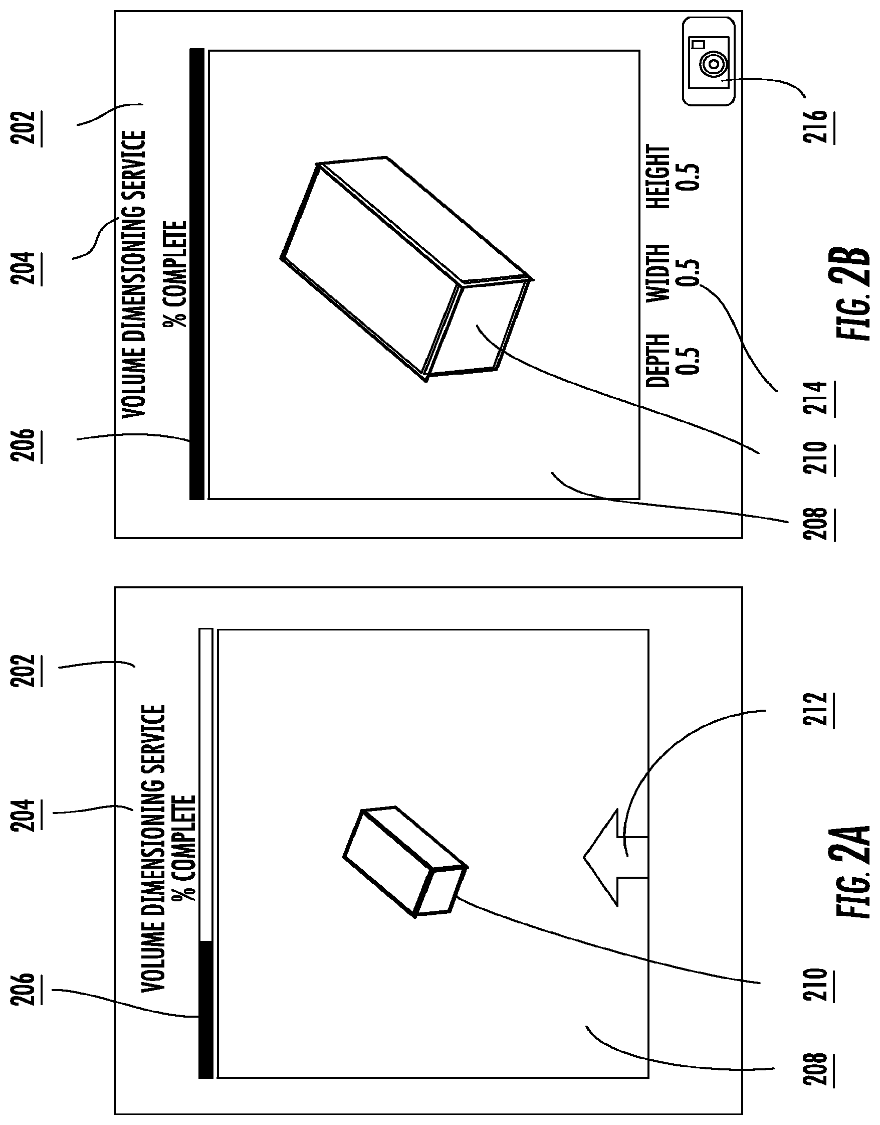
[0037] FIG. 2A is an example of a graphical user interface (GUI) that would be displayed on the display 142 of the mobile dimensioning device 100 in accordance with one embodiment of the disclosed subject matter. FIG. 2A is a representative GUI during the phase while the mobile dimensioning device is finding a sufficient measurement environment for measuring an object.
[0038] The elements of FIG. 2A are now described. The main window of the interface 202 has a title field 204 and a progress bar 206 as well as a viewing window 208. The viewing window 208 currently shows an object to be measured 210, for example, a box to be shipped. In some embodiments, the object to be measured 210 can be highlighted in the viewing window 208 in some manner, such as with a green outline. Overlaid onto or integrated with the viewing window 208 is a guidance indication 212, represented by, but not limited to, an arrow in FIG. 2A.
[0039] The guidance indication 212 may be a textual instruction, a graphical instruction, a graphical icon, or any combination therein. The guidance indication 212 provides information that guides the mobile dimensioning device 100 to a measurement environment sufficient for measuring an object. The guidance indication 212 is based on the dynamic accuracy level of the mobile dimensioning device 100.
[0040] In a preprocessing phase, the mobile dimensioning device 100 computes its accuracy level dynamically as a function of all of the parameters that influence it. Any kind of measureable parameter influencing accuracy can be included in the model for computing the accuracy level of the mobile dimensioning device 100. The list of parameters includes, but is not limited to, distance of the mobile dimensioning device 100 to the object being measured, the viewing angle of the camera or optical sensor in the mobile dimensioning device 100 relative to the object being measured, temperature of the mobile dimensioning device 100, ambient light, and quality of data from the one or more sensors of the mobile dimensioning device 100. Individually and collectively, these parameters make up the measuring environment for measuring the object. In one embodiment, the accuracy level may be computed, for example, using multivariable regression on the parameters influencing the accuracy.
[0041] Note that in some embodiments, the mobile dimensioning device 100 records a variety of raw data from the sensors. The mobile dimensioner device, through hardware and software, transforms that data into the accuracy parameters that are used to compute the accuracy level for a given the measurement environment.
[0042] Once the dynamic accuracy level is computed, it is used to guide the mobile dimensioning device 100 to a measurement environment sufficient for measuring the object. In one embodiment, this is accomplished by identifying accuracy levels with a low accuracy division value. In general, dimensioning error is reduced as the mobile dimensioning device 100 gets closer to the object and has the proper viewing angle for capturing the object, thus reducing the accuracy division. The lower the accuracy division value, the more optimal the measuring environment.
[0043] Examples of the types of guidance provided by the guidance indication 212 include, but are not limited to, shortening the distance to the object, improving the viewing angle relative to the object, delaying measurement pending a target operating temperature, and improving the ambient light, adjusting the one or more sensors to improve the quality of data.
[0044] In some embodiments, the progress bar 206 appears with other guidance indications 212. As shown in FIG. 2A, the progress bar 206 works in tandem with the guidance indication 212 to guide the mobile dimensioning device 100 to a sufficient measurement environment, showing a reading of 0% complete when the mobile dimensioning device has an insufficient measurement environment and 100% when the mobile dimensioning device has found a sufficient measurement environment.
[0045] FIG. 2B is an example of a GUI of the system in accordance with one embodiment of the disclosed subject matter. FIG. 2A is a representative GUI after the mobile dimensioning device has found a sufficient measurement environment for measuring an object.
[0046] FIG. 2B adds some additional elements beyond FIG. 2A. Once the mobile dimensioning device has found a sufficient measurement environment for measuring an object, the mobile dimensioning device 100 displays an accuracy division field 214. In FIG. 2B, the accuracy division field 214 shows one accuracy division per dimension, but the present invention is not limited thereto. Note also that the progress bar 206 now shows 100%, indicating that the measurement environment is sufficient. FIG. 2A also shows a capture icon 216 which is used to capture the measurement of the object in response to an input at the mobile dimensioning device 100. In other embodiments, the capture icon 216 could be implemented in any of a variety of ways using different elements understood in the art of GUI design for receiving input. In other embodiments, the capture icon 216 would not be part of the GUI but rather would be a hardware button on the mobile dimensioning device 100 that becomes active when the device is enabled to capture the measurement. Note that the capture icon 216 is only visible when the measuring environment is sufficient for measuring the object. Note also that the guidance indication 212 is no longer shown, as the mobile dimensioning device has found a sufficient environment for taking the measurement. All of these visual cues in the GUI (i.e. the displaying of the accuracy division field 214, the completed progress bar 206, the capture icon 216, and the absence of the guidance indication 212) are examples of indications that the measurement environment is sufficient.
[0047] Note that because mobile dimensioning device 100 reveals the accuracy division prior to permitting or enabling the actual measurement of the object, the mobile dimensioning device is compatible with the NIST standard.
[0048] FIG. 2C is an example of a GUI of the system in accordance with one embodiment of the disclosed subject matter. FIG. 2C is a representative GUI after the mobile dimensioning device 100 has captured the measurements of the object.
[0049] In some embodiments, the mobile dimensioner device 100 records an infra-red (IR) image of a pattern of light projected on an object being measured. The mobile dimensioner device, though hardware and software, transform the image into three dimensional data about the object. That three dimensional data is used to derive an accurate measurement for the object. This process of deriving the accurate measurement for the object is known as capturing the measurement. Capturing the measurement can be done by the mobile dimensioning device 100 after the accuracy division has been displayed either automatically or in response to an input.
[0050] FIG. 2C adds some additional elements beyond FIG. 2A and FIG. 2B. Because the measurement has now been captured, it is possible to present the dimension field 220. In some embodiments, and additional confirmation icon 218 is provided to confirm that the measurement has been captured, such as but not limited to the check mark icon shown in FIG. 2C.
[0051] FIGS. 3A, 3B, 3C, and 3D are an example of a GUI of the system in accordance with an alternative embodiment of the disclosed subject matter. In this embodiment, neither the dimensions of the object nor the accuracy division are shown until the measurement environment is sufficient for measuring the object. Then a button or icon is shown to enable the capture.
[0052] FIG. 3A has similar elements to FIG. 2A. FIG. 3A shows the preprocessing phase of the alternative embodiment. The main window of the interface 302 has a title field 304 and a progress bar 306 as well as a viewing window 308. The viewing window 308 currently shows an object to be measured 310, for example, a box to be shipped. In some embodiments, the object to be measured 310 can be highlighted in the viewing window 308 in some manner, such as with a green outline. Overlaid onto or integrated with the viewing window 308 is a guidance indication 312, represented by, but not limited to, an arrow in FIG. 3A. As described earlier, the guidance indication 312 may be a textual instruction, a graphical instruction, a graphical icon, or any combination therein.
[0053] Also, as discussed earlier, in the background the mobile dimensioning device 100 computes its accuracy level dynamically to help the mobile dimensioning device 100 identify a measurement environment sufficient for measuring the object.
[0054] FIG. 3B is similar to FIG. 2B. FIG. 3B is a representative GUI after the mobile dimensioning device has found a sufficient measurement environment for measuring an object according to the alternative embodiment.
[0055] In FIG. 3B, the progress bar 206 now shows 100%, indicating that the measurement environment is sufficient. In this alternative embodiment, an acceptance icon 322 is provided to confirm that the measurement environment is sufficient to measure the object. Note that neither the dimensions nor the accuracy division are shown in FIG. 3B. The acceptance icon 322 enables the display of the accuracy level.
[0056] In response to an input received at the acceptance icon 322, the accuracy level will be displayed as shown in FIG. 3C. Note that only the accuracy division field 314 is shown. FIG. 3C also provides a capture icon 316 to enable the measurement capture. In response to an input involving the capture icon 316, the mobile dimensioning device will capture the measurements. In other embodiments, recording the measurements may be automatic after capture.
[0057] FIG. 3D is an exemplary GUI that is displayed after the measurement has been captured. Note now that both the accuracy division field 314 and the actual dimension field 320 are both shown. In some embodiments, an additional confirmation icon 318, such as but not limited to the check mark icon shown in FIG. 3D, is provided to confirm that the measurement has been captured.
[0058] FIG. 4 is a flow chart outlining the process for operating a mobile dimensioning device in accordance with embodiments of the disclosed subject matter.
[0059] The process begins in FIG. 4 at Step 400 followed by Step 402 in which a check is made to see if an adjustment to the mobile dimensioning device has been detected. The adjustment to the mobile dimensioning device can be a random movement of the device itself or any of the components of the device. In some embodiments, the adjustment to the mobile dimensioning device represents movements that correspond to the types of guidance described earlier by the guidance indication 212, 312. If no adjustment has been detected (Path 403), then the process ends (Step 422).
[0060] If an adjustment has been detected (Step 405), then the mobile dimensioning device 100 derives the new accuracy parameters that correspond to the new measurement environment (i.e. the measurement environment after the adjustment to the mobile dimensioning device) based on information received from the sensors (Step 404). The mobile dimensioning device 100 then compute an accuracy level based on the one or more accuracy parameters (Step 406).
[0061] The mobile dimensioning device 100 then checks to see if the measurement environment is sufficient for measurement of the object (Step 408). If not (Path 407), then guidance indications for improving the measurement environment are displayed (Step 410). The indications for improving the measurement environment were described earlier. These are the guidance indications 212, 312. Examples include, but are not limited to, shortening the distance to the object, improving the viewing angle relative to the object, delaying measurement pending a target operating temperature, and improving the ambient light, adjusting the one or more sensors to improve the quality of data.
[0062] If the measurement environment is sufficient for measurement of the object (Path 409), then the mobile dimensioning device displays indications of sufficient measurement environment (Step 412). As described earlier, the indication of sufficient measurement environment include but are not limited to: displaying of the accuracy division, displaying a completed progress bar, displaying a capture icon, and the removal of the guidance indications.
[0063] The mobile dimensioning device 100 then checks to see if a capture event is received (Step 414). The capture event triggers the actual measurement of the object. In some embodiments, the capture event occurs automatically. In other embodiments, the capture event occurs in response to an input received at the mobile dimensioning device 100.
[0064] If no capture event is detected (Path 411), then the mobile dimensioner device checks to see if an adjustment has been detected (Step 402) as described earlier.
[0065] If a capture event is detected (Path 413), then the dimensions of the object are actually measured (Step 416), the dimensions are displayed (Step 418), and the dimensions are recorded (Step 420). In some embodiments, when the object dimensions are displayed, the associated accuracy division for each dimension is also displayed. In other embodiments, only the object dimensions are displayed. The process then ends (Step 422).
[0066] In this respect, the processes described in the figures should make it clear to a person of ordinary skill in the art how the mobile dimensioner device 100 of the present invention uses a dynamic accuracy while still being compatible with the NIST standard and can therefore be certified and used in commercial transactions.
To supplement the present disclosure, this application incorporates entirely by reference the following commonly assigned patents, patent application publications, and patent applications: U.S. Pat. No. 6,832,725; [0067] U.S. Pat. No. 7,128,266; [0068] U.S. Pat. Nos. 7,159,783; 7,413,127; [0069] U.S. Pat. Nos. 7,726,575; 8,294,969; [0070] U.S. Pat. Nos. 8,317,105; 8,322,622; [0071] U.S. Pat. Nos. 8,366,005; 8,371,507; [0072] U.S. Pat. Nos. 8,376,233; 8,381,979; [0073] U.S. Pat. Nos. 8,390,909; 8,408,464; [0074] U.S. Pat. Nos. 8,408,468; 8,408,469; [0075] U.S. Pat. Nos. 8,424,768; 8,448,863; [0076] U.S. Pat. Nos. 8,457,013; 8,459,557; [0077] U.S. Pat. No. 8,463,079; [0078] U.S. Pat. Nos. 8,469,272; 8,474,712; [0079] U.S. Pat. Nos. 8,479,992; 8,490,877; [0080] U.S. Pat. Nos. 8,517,271; 8,523,076; [0081] U.S. Pat. Nos. 8,528,818; 8,544,737; [0082] U.S. Pat. Nos. 8,548,242; 8,548,420; [0083] U.S. Pat. Nos. 8,550,335; 8,550,354; [0084] U.S. Pat. Nos. 8,550,357; 8,556,174; [0085] U.S. Pat. Nos. 8,556,176; 8,556,177; [0086] U.S. Pat. Nos. 8,559,767; 8,599,957; [0087] U.S. Pat. Nos. 8,561,895; 8,561,903; [0088] U.S. Pat. Nos. 8,561,905; 8,565,107; [0089] U.S. Pat. Nos. 8,571,307; 8,579,200; [0090] U.S. Pat. Nos. 8,583,924; 8,584,945; [0091] U.S. Pat. Nos. 8,587,595; 8,587,697; [0092] U.S. Pat. Nos. 8,588,869; 8,590,789; [0093] U.S. Pat. Nos. 8,596,539; 8,596,542; [0094] U.S. Pat. Nos. 8,596,543; 8,599,271; [0095] U.S. Pat. Nos. 8,599,957; 8,600,158; [0096] U.S. Pat. Nos. 8,600,167; 8,602,309; [0097] U.S. Pat. Nos. 8,608,053; 8,608,071; [0098] U.S. Pat. Nos. 8,611,309; 8,615,487; [0099] U.S. Pat. Nos. 8,616,454; 8,621,123; [0100] U.S. Pat. Nos. 8,622,303; 8,628,013; [0101] U.S. Pat. Nos. 8,628,015; 8,628,016; [0102] U.S. Pat. Nos. 8,629,926; 8,630,491; [0103] U.S. Pat. Nos. 8,635,309; 8,636,200; [0104] U.S. Pat. Nos. 8,636,212; 8,636,215; [0105] U.S. Pat. Nos. 8,636,224; 8,638,806; [0106] U.S. Pat. Nos. 8,640,958; 8,640,960; [0107] U.S. Pat. Nos. 8,643,717; 8,646,692; [0108] U.S. Pat. Nos. 8,646,694; 8,657,200; [0109] U.S. Pat. Nos. 8,659,397; 8,668,149; [0110] U.S. Pat. Nos. 8,678,285; 8,678,286; [0111] U.S. Pat. Nos. 8,682,077; 8,687,282; [0112] U.S. Pat. Nos. 8,692,927; 8,695,880; [0113] U.S. Pat. Nos. 8,698,949; 8,717,494; [0114] U.S. Pat. Nos. 8,717,494; 8,720,783; [0115] U.S. Pat. Nos. 8,723,804; 8,723,904; [0116] U.S. Pat. No. 8,727,223; U.S. Pat. No. D702,237; [0117] U.S. Pat. Nos. 8,740,082; 8,740,085; [0118] U.S. Pat. Nos. 8,746,563; 8,750,445; [0119] U.S. Pat. Nos. 8,752,766; 8,756,059; [0120] U.S. Pat. Nos. 8,757,495; 8,760,563; [0121] U.S. Pat. Nos. 8,763,909; 8,777,108; [0122] U.S. Pat. Nos. 8,777,109; 8,779,898; [0123] U.S. Pat. Nos. 8,781,520; 8,783,573; [0124] U.S. Pat. Nos. 8,789,757; 8,789,758; [0125] U.S. Pat. Nos. 8,789,759; 8,794,520; [0126] U.S. Pat. Nos. 8,794,522; 8,794,526; [0127] U.S. Pat. Nos. 8,798,367; 8,807,431; [0128] U.S. Pat. Nos. 8,807,432; 8,820,630; [0129] U.S. Pat. No. 8,854,633; [0130] International Publication No. 2013/163789; [0131] International Publication No. 2013/173985; [0132] International Publication No. 2014/019130; [0133] International Publication No. 2014/110495; [0134] U.S. Patent Application Publication No. 2008/0185432; [0135] U.S. Patent Application Publication No. 2009/0134221; [0136] U.S. Patent Application Publication No. 2010/0177080; [0137] U.S. Patent Application Publication No. 2010/0177076; [0138] U.S. Patent Application Publication No. 2010/0177707; [0139] U.S. Patent Application Publication No. 2010/0177749; [0140] U.S. Patent Application Publication No. 2010/0202702; [0141] U.S. Patent Application Publication No. 2010/0220894; [0142] U.S. Patent Application Publication No. 2011/0202554; [0143] U.S. Patent Application Publication No. 2012/0111946; [0144] U.S. Patent Application Publication No. 2012/0138685; [0145] U.S. Patent Application Publication No. 2012/0168511; [0146] U.S. Patent Application Publication No. 2012/0168512; [0147] U.S. Patent Application Publication No. 2012/0193423; [0148] U.S. Patent Application Publication No. 2012/0203647; [0149] U.S. Patent Application Publication No. 2012/0223141; [0150] U.S. Patent Application Publication No. 2012/0228382; [0151] U.S. Patent Application Publication No. 2012/0248188; [0152] U.S. Patent Application Publication No. 2013/0043312; [0153] U.S. Patent Application Publication No. 2013/0056285; [0154] U.S. Patent Application Publication No. 2013/0070322; [0155] U.S. Patent Application Publication No. 2013/0075168; [0156] U.S. Patent Application Publication No. 2013/0082104; [0157] U.S. Patent Application Publication No. 2013/0175341; [0158] U.S. Patent Application Publication No. 2013/0175343; [0159] U.S. Patent Application Publication No. 2013/0200158; [0160] U.S. Patent Application Publication No. 2013/0256418; [0161] U.S. Patent Application Publication No. 2013/0257744; [0162] U.S. Patent Application Publication No. 2013/0257759; [0163] U.S. Patent Application Publication No. 2013/0270346; [0164] U.S. Patent Application Publication No. 2013/0278425; [0165] U.S. Patent Application Publication No. 2013/0287258; [0166] U.S. Patent Application Publication No. 2013/0292475; [0167] U.S. Patent Application Publication No. 2013/0292477; [0168] U.S. Patent Application Publication No. 2013/0293539; [0169] U.S. Patent Application Publication No. 2013/0293540; [0170] U.S. Patent Application Publication No. 2013/0306728; [0171] U.S. Patent Application Publication No. 2013/0306730; [0172] U.S. Patent Application Publication No. 2013/0306731; [0173] U.S. Patent Application Publication No. 2013/0307964; [0174] U.S. Patent Application Publication No. 2013/0308625; [0175] U.S. Patent Application Publication No. 2013/0313324; [0176] U.S. Patent Application Publication No. 2013/0313325; [0177] U.S. Patent Application Publication No. 2013/0341399; [0178] U.S. Patent Application Publication No. 2013/0342717; [0179] U.S. Patent Application Publication No. 2014/0001267; [0180] U.S. Patent Application Publication No. 2014/0002828; [0181] U.S. Patent Application Publication No. 2014/0008430; [0182] U.S. Patent Application Publication No. 2014/0008439; [0183] U.S. Patent Application Publication No. 2014/0025584; [0184] U.S. Patent Application Publication No. 2014/0027518; [0185] U.S. Patent Application Publication No. 2014/0034734; [0186] U.S. Patent Application Publication No. 2014/0036848; [0187] U.S. Patent Application Publication No. 2014/0039693; [0188] U.S. Patent Application Publication No. 2014/0042814; [0189] U.S. Patent Application Publication No. 2014/0049120; [0190] U.S. Patent Application Publication No. 2014/0049635; [0191] U.S. Patent Application Publication No. 2014/0061305; [0192] U.S. Patent Application Publication No. 2014/0061306; [0193] U.S. Patent Application Publication No. 2014/0063289; [0194] U.S. Patent Application Publication No. 2014/0066136; [0195] U.S. Patent Application Publication No. 2014/0067692; [0196] U.S. Patent Application Publication No. 2014/0070005; [0197] U.S. Patent Application Publication No. 2014/0071840; [0198] U.S. Patent Application Publication No. 2014/0074746; [0199] U.S. Patent Application Publication No. 2014/0075846; [0200] U.S. Patent Application Publication No. 2014/0076974; [0201] U.S. Patent Application Publication No. 2014/0078341; [0202] U.S. Patent Application Publication No. 2014/0078342; [0203] U.S. Patent Application Publication No. 2014/0078345; [0204] U.S. Patent Application Publication No. 2014/0084068; [0205] U.S. Patent Application Publication No. 2014/0097249; [0206] U.S. Patent Application Publication No. 2014/0098792; [0207] U.S. Patent Application Publication No. 2014/0100774; [0208] U.S. Patent Application Publication No. 2014/0100813; [0209] U.S. Patent Application Publication No. 2014/0103115; [0210] U.S. Patent Application Publication No. 2014/0104413; [0211] U.S. Patent Application Publication No. 2014/0104414; [0212] U.S. Patent Application Publication No. 2014/0104416; [0213] U.S. Patent Application Publication No. 2014/0104451; [0214] U.S. Patent Application Publication No. 2014/0106594; [0215] U.S. Patent Application Publication No. 2014/0106725; [0216] U.S. Patent Application Publication No. 2014/0108010; [0217] U.S. Patent Application Publication No. 2014/0108402; [0218] U.S. Patent Application Publication No. 2014/0108682; [0219] U.S. Patent Application Publication No. 2014/0110485; [0220] U.S. Patent Application Publication No. 2014/0114530; [0221] U.S. Patent Application Publication No. 2014/0124577; [0222] U.S. Patent Application Publication No. 2014/0124579; [0223] U.S. Patent Application Publication No. 2014/0125842; [0224] U.S. Patent Application Publication No. 2014/0125853; [0225] U.S. Patent Application Publication No. 2014/0125999; [0226] U.S. Patent Application Publication No. 2014/0129378; [0227] U.S. Patent Application Publication No. 2014/0131438; [0228] U.S. Patent Application Publication No. 2014/0131441; [0229] U.S. Patent Application Publication No. 2014/0131443; [0230] U.S. Patent Application Publication No. 2014/0131444; [0231] U.S. Patent Application Publication No. 2014/0131445; [0232] U.S. Patent Application Publication No. 2014/0131448; [0233] U.S. Patent Application Publication No. 2014/0133379; [0234] U.S. Patent Application Publication No. 2014/0136208; [0235] U.S. Patent Application Publication No. 2014/0140585; [0236] U.S. Patent Application Publication No. 2014/0151453; [0237] U.S. Patent Application Publication No. 2014/0152882; [0238] U.S. Patent Application Publication No. 2014/0158770; [0239] U.S. Patent Application Publication No. 2014/0159869; [0240] U.S. Patent Application Publication No. 2014/0160329; [0241] U.S. Patent Application Publication No. 2014/0166755; [0242] U.S. Patent Application Publication No. 2014/0166757; [0243] U.S. Patent Application Publication No. 2014/0166759; [0244] U.S. Patent Application Publication No. 2014/0166760; [0245] U.S. Patent Application Publication No. 2014/0166761; [0246] U.S. Patent Application Publication No. 2014/0168787; [0247] U.S. Patent Application Publication No. 2014/0175165; [0248] U.S. Patent Application Publication No. 2014/0175169; [0249] U.S. Patent Application Publication No. 2014/0175172; [0250] U.S. Patent Application Publication No. 2014/0175174; [0251] U.S. Patent Application Publication No. 2014/0191644; [0252] U.S. Patent Application Publication No. 2014/0191913; [0253] U.S. Patent Application Publication No. 2014/0197238; [0254] U.S. Patent Application Publication No. 2014/0197239; [0255] U.S. Patent Application Publication No. 2014/0197304; [0256] U.S. Patent Application Publication No. 2014/0203087; [0257] U.S. Patent Application Publication No. 2014/0204268; [0258] U.S. Patent Application Publication No. 2014/0214631; [0259] U.S. Patent Application Publication No. 2014/0217166; [0260] U.S. Patent Application Publication No. 2014/0217180; [0261] U.S. Patent Application Publication No. 2014/0267609; [0262] U.S. patent application Ser. No. 13/367,978 for a Laser Scanning Module Employing an Elastomeric U-Hinge Based Laser Scanning Assembly, filed Feb. 7, 2012 (Feng et al.); [0263] U.S. patent application Ser. No. 29/436,337 for an Electronic Device, filed Nov. 5, 2012 (Fitch et al.); [0264] U.S. patent application Ser. No. 13/771,508 for an Optical Redirection Adapter, filed Feb. 20, 2013 (Anderson); [0265] U.S. patent application Ser. No. 13/852,097 for a System and Method for Capturing and Preserving Vehicle Event Data, filed Mar. 28, 2013 (Barker et al.); [0266] U.S. patent application Ser. No. 13/902,110 for a System and Method for Display of Information Using a Vehicle-Mount Computer, filed May 24, 2013 (Hollifield); [0267] U.S. patent application Ser. No. 13/902,144, for a System and Method for Display of Information Using a Vehicle-Mount Computer, filed May 24, 2013 (Chamberlin); [0268] U.S. patent application Ser. No. 13/902,242 for a System For Providing A Continuous Communication Link With A Symbol Reading Device, filed May 24, 2013 (Smith et al.); [0269] U.S. patent application Ser. No. 13/912,262 for a Method of Error Correction for 3D Imaging Device, filed Jun. 7, 2013 (Jovanovski et al.); [0270] U.S. patent application Ser. No. 13/912,702 for a System and Method for Reading Code Symbols at Long Range Using Source Power Control, filed Jun. 7, 2013 (Xian et al.); [0271] U.S. patent application Ser. No. 29/458,405 for an Electronic Device, filed Jun. 19, 2013 (Fitch et al.); [0272] U.S. patent application Ser. No. 13/922,339 for a System and Method for Reading Code Symbols Using a Variable Field of View, filed Jun. 20, 2013 (Xian et al.); [0273] U.S. patent application Ser. No. 13/927,398 for a Code Symbol Reading System Having Adaptive Autofocus, filed Jun. 26, 2013 (Todeschini); [0274] U.S. patent application Ser. No. 13/930,913 for a Mobile Device Having an Improved User Interface for Reading Code Symbols, filed Jun. 28, 2013 (Gelay et al.); [0275] U.S. patent application Ser. No. 29/459,620 for an Electronic Device Enclosure, filed Jul. 2, 2013 (London et al.); [0276] U.S. patent application Ser. No. 29/459,681 for an Electronic Device Enclosure, filed Jul. 2, 2013 (Chaney et al.); [0277] U.S. patent application Ser. No. 13/933,415 for an Electronic Device Case, filed Jul. 2, 2013 (London et al.); [0278] U.S. patent application Ser. No. 29/459,785 for a Scanner and Charging Base, filed Jul. 3, 2013 (Fitch et al.); [0279] U.S. patent application Ser. No. 29/459,823 for a Scanner, filed Jul. 3, 2013 (Zhou et al.); [0280] U.S. patent application Ser. No. 13/947,296 for a System and Method for Selectively Reading Code Symbols, filed Jul. 22, 2013 (Rueblinger et al.); [0281] U.S. patent application Ser. No. 13/950,544 for a Code Symbol Reading System Having Adjustable Object Detection, filed Jul. 25, 2013 (Jiang); [0282] U.S. patent application Ser. No. 13/961,408 for a Method for Manufacturing Laser Scanners, filed Aug. 7, 2013 (Saber et al.); [0283] U.S. patent application Ser. No. 14/018,729 for a Method for Operating a Laser Scanner, filed Sep. 5, 2013 (Feng et al.); [0284] U.S. patent application Ser. No. 14/019,616 for a Device Having Light Source to Reduce Surface Pathogens, filed Sep. 6, 2013 (Todeschini); [0285] U.S. patent application Ser. No. 14/023,762 for a Handheld Indicia Reader Having Locking Endcap, filed Sep. 11, 2013 (Gannon); [0286] U.S. patent application Ser. No. 14/035,474 for Augmented-Reality Signature Capture, filed Sep. 24, 2013 (Todeschini); [0287] U.S. patent application Ser. No. 29/468,118 for an Electronic Device Case, filed Sep. 26, 2013 (Oberpriller et al.); [0288] U.S. patent application Ser. No. 14/055,234 for Dimensioning System, filed Oct. 16, 2013 (Fletcher); [0289] U.S. patent application Ser. No. 14/053,314 for Indicia Reader, filed Oct. 14, 2013 (Huck); [0290] U.S. patent application Ser. No. 14/065,768 for Hybrid System and Method for Reading Indicia, filed Oct. 29, 2013 (Meier et al.); [0291] U.S. patent application Ser. No. 14/074,746 for Self-Checkout Shopping System, filed Nov. 8, 2013 (Hejl et al.);
[0292] U.S. patent application Ser. No. 14/074,787 for Method and System for Configuring Mobile Devices via NFC Technology, filed Nov. 8, 2013 (Smith et al.); [0293] U.S. patent application Ser. No. 14/087,190 for Optimal Range Indicators for Bar Code Validation, filed Nov. 22, 2013 (Hejl); [0294] U.S. patent application Ser. No. 14/094,087 for Method and System for Communicating Information in an Digital Signal, filed Dec. 2, 2013 (Peake et al.); [0295] U.S. patent application Ser. No. 14/101,965 for High Dynamic-Range Indicia Reading System, filed Dec. 10, 2013 (Xian); [0296] U.S. patent application Ser. No. 14/150,393 for Indicia-reader Having Unitary Construction Scanner, filed Jan. 8, 2014 (Colavito et al.); [0297] U.S. patent application Ser. No. 14/154,207 for Laser Barcode Scanner, filed Jan. 14, 2014 (Hou et al.); [0298] U.S. patent application Ser. No. 14/165,980 for System and Method for Measuring Irregular Objects with a Single Camera filed Jan. 28, 2014 (Li et al.); [0299] U.S. patent application Ser. No. 14/166,103 for Indicia Reading Terminal Including Optical Filter filed Jan. 28, 2014 (Lu et al.); [0300] U.S. patent application Ser. No. 14/200,405 for Indicia Reader for Size-Limited Applications filed Mar. 7, 2014 (Feng et al.); [0301] U.S. patent application Ser. No. 14/231,898 for Hand-Mounted Indicia-Reading Device with Finger Motion Triggering filed Apr. 1, 2014 (Van Horn et al.); [0302] U.S. patent application Ser. No. 14/250,923 for Reading Apparatus Having Partial Frame Operating Mode filed Apr. 11, 2014, (Deng et al.); [0303] U.S. patent application Ser. No. 14/257,174 for Imaging Terminal Having Data Compression filed Apr. 21, 2014, (Barber et al.); [0304] U.S. patent application Ser. No. 14/257,364 for Docking System and Method Using Near Field Communication filed Apr. 21, 2014 (Showering); [0305] U.S. patent application Ser. No. 14/264,173 for Autofocus Lens System for Indicia Readers filed Apr. 29, 2014 (Ackley et al.); [0306] U.S. patent application Ser. No. 14/274,858 for Mobile Printer with Optional Battery Accessory filed May 12, 2014 (Marty et al.); [0307] U.S. patent application Ser. No. 14/277,337 for MULTIPURPOSE OPTICAL READER, filed May 14, 2014 (Jovanovski et al.); [0308] U.S. patent application Ser. No. 14/283,282 for TERMINAL HAVING ILLUMINATION AND FOCUS CONTROL filed May 21, 2014 (Liu et al.); [0309] U.S. patent application Ser. No. 14/300,276 for METHOD AND SYSTEM FOR CONSIDERING INFORMATION ABOUT AN EXPECTED RESPONSE WHEN PERFORMING SPEECH RECOGNITION, filed Jun. 10, 2014 (Braho et al.); [0310] U.S. patent application Ser. No. 14/305,153 for INDICIA READING SYSTEM EMPLOYING DIGITAL GAIN CONTROL filed Jun. 16, 2014 (Xian et al.); [0311] U.S. patent application Ser. No. 14/310,226 for AUTOFOCUSING OPTICAL IMAGING DEVICE filed Jun. 20, 2014 (Koziol et al.); [0312] U.S. patent application Ser. No. 14/327,722 for CUSTOMER FACING IMAGING SYSTEMS AND METHODS FOR OBTAINING IMAGES filed Jul. 10, 2014 (Oberpriller et al,); [0313] U.S. patent application Ser. No. 14/327,827 for a MOBILE-PHONE ADAPTER FOR ELECTRONIC TRANSACTIONS, filed Jul. 10, 2014 (Hejl); [0314] U.S. patent application Ser. No. 14/329,303 for CELL PHONE READING MODE USING IMAGE TIMER filed Jul. 11, 2014 (Coyle); [0315] U.S. patent application Ser. No. 14/333,588 for SYMBOL READING SYSTEM WITH INTEGRATED SCALE BASE filed Jul. 17, 2014 (Barten); [0316] U.S. patent application Ser. No. 14/334,934 for a SYSTEM AND METHOD FOR INDICIA VERIFICATION, filed Jul. 18, 2014 (Hejl); [0317] U.S. patent application Ser. No. 14/336,188 for METHOD OF AND SYSTEM FOR DETECTING OBJECT WEIGHING INTERFERENCES, Filed Jul. 21, 2014 (Amundsen et al.); [0318] U.S. patent application Ser. No. 14/339,708 for LASER SCANNING CODE SYMBOL READING SYSTEM, filed Jul. 24, 2014 (Xian et al.); [0319] U.S. patent application Ser. No. 14/340,627 for an AXIALLY REINFORCED FLEXIBLE SCAN ELEMENT, filed Jul. 25, 2014 (Rueblinger et al.); [0320] U.S. patent application Ser. No. 14/340,716 for an OPTICAL IMAGER AND METHOD FOR CORRELATING A MEDICATION PACKAGE WITH A PATIENT, filed Jul. 25, 2014 (Ellis); [0321] U.S. patent application Ser. No. 14/342,544 for Imaging Based Barcode Scanner Engine with Multiple Elements Supported on a Common Printed Circuit Board filed Mar. 4, 2014 (Liu et al.); [0322] U.S. patent application Ser. No. 14/345,735 for Optical Indicia Reading Terminal with Combined Illumination filed Mar. 19, 2014 (Ouyang); [0323] U.S. patent application Ser. No. 14/336,188 for METHOD OF AND SYSTEM FOR DETECTING OBJECT WEIGHING INTERFERENCES, Filed Jul. 21, 2014 (Amundsen et al.); [0324] U.S. patent application Ser. No. 14/355,613 for Optical Indicia Reading Terminal with Color Image Sensor filed May 1, 2014 (Lu et al.); [0325] U.S. patent application Ser. No. 14/370,237 for WEB-BASED SCAN-TASK ENABLED SYSTEM AND METHOD OF AND APPARATUS FOR DEVELOPING AND DEPLOYING THE SAME ON A CLIENT-SERVER NETWORK filed Jul. 2, 2014 (Chen et al.); [0326] U.S. patent application Ser. No. 14/370,267 for INDUSTRIAL DESIGN FOR CONSUMER DEVICE BASED SCANNING AND MOBILITY, filed Jul. 2, 2014 (Ma et al.); [0327] U.S. patent application Ser. No. 14/376,472, for an ENCODED INFORMATION READING TERMINAL INCLUDING HTTP SERVER, filed Aug. 4, 2014 (Lu); [0328] U.S. patent application Ser. No. 14/379,057 for METHOD OF USING CAMERA SENSOR INTERFACE TO TRANSFER MULTIPLE CHANNELS OF SCAN DATA USING AN IMAGE FORMAT filed Aug. 15, 2014 (Wang et al.); [0329] U.S. patent application Ser. No. 14/452,697 for INTERACTIVE INDICIA READER, filed Aug. 6, 2014 (Todeschini); [0330] U.S. patent application Ser. No. 14/453,019 for DIMENSIONING SYSTEM WITH GUIDED ALIGNMENT, filed Aug. 6, 2014 (Li et al.); [0331] U.S. patent application Ser. No. 14/460,387 for APPARATUS FOR DISPLAYING BAR CODES FROM LIGHT EMITTING DISPLAY SURFACES filed Aug. 15, 2014 (Van Horn et al.); [0332] U.S. patent application Ser. No. 14/460,829 for ENCODED INFORMATION READING TERMINAL WITH WIRELESS PATH SELECTON CAPABILITY, filed Aug. 15, 2014 (Wang et al.); [0333] U.S. patent application Ser. No. 14/462,801 for MOBILE COMPUTING DEVICE WITH DATA COGNITION SOFTWARE, filed on Aug. 19, 2014 (Todeschini et al.); [0334] U.S. patent application Ser. No. 14/446,387 for INDICIA READING TERMINAL PROCESSING PLURALITY OF FRAMES OF IMAGE DATA RESPONSIVELY TO TRIGGER SIGNAL ACTIVATION filed Jul. 30, 2014 (Wang et al.); [0335] U.S. patent application Ser. No. 14/446,391 for MULTIFUNCTION POINT OF SALE APPARATUS WITH OPTICAL SIGNATURE CAPTURE filed Jul. 30, 2014 (Good et al.); [0336] U.S. patent application Ser. No. 29/486,759 for an Imaging Terminal, filed Apr. 2, 2014 (Oberpriller et al.); [0337] U.S. patent application Ser. No. 29/492,903 for an INDICIA SCANNER, filed Jun. 4, 2014 (Zhou et al.); and [0338] U.S. patent application Ser. No. 29/494,725 for an IN-COUNTER BARCODE SCANNER, filed Jun. 24, 2014 (Oberpriller et al.).
[0339] In the specification and/or figures, typical embodiments of the invention have been disclosed. The present invention is not limited to such exemplary embodiments. The use of the term "and/or" includes any and all combinations of one or more of the associated listed items. The figures are schematic representations and so are not necessarily drawn to scale. Unless otherwise noted, specific terms have been used in a generic and descriptive sense and not for purposes of limitation.
* * * * *
D00000
D00001
D00002
D00003
D00004
D00005
D00006
XML
uspto.report is an independent third-party trademark research tool that is not affiliated, endorsed, or sponsored by the United States Patent and Trademark Office (USPTO) or any other governmental organization. The information provided by uspto.report is based on publicly available data at the time of writing and is intended for informational purposes only.
While we strive to provide accurate and up-to-date information, we do not guarantee the accuracy, completeness, reliability, or suitability of the information displayed on this site. The use of this site is at your own risk. Any reliance you place on such information is therefore strictly at your own risk.
All official trademark data, including owner information, should be verified by visiting the official USPTO website at www.uspto.gov. This site is not intended to replace professional legal advice and should not be used as a substitute for consulting with a legal professional who is knowledgeable about trademark law.