Loop Vapor Chamber
TSENG; Chuan-Chi ; et al.
U.S. patent application number 16/051916 was filed with the patent office on 2019-11-07 for loop vapor chamber. The applicant listed for this patent is TAI-SOL ELECTRONICS CO., LTD.. Invention is credited to Ming-Quan CUI, Wen-Ching LIAO, Chuan-Chi TSENG.
| Application Number | 20190339022 16/051916 |
| Document ID | / |
| Family ID | 68383847 |
| Filed Date | 2019-11-07 |


| United States Patent Application | 20190339022 |
| Kind Code | A1 |
| TSENG; Chuan-Chi ; et al. | November 7, 2019 |
LOOP VAPOR CHAMBER
Abstract
A loop vapor chamber includes: a base board having therein a space; a lid for covering the base board and sealing the space to form therein an evaporation chamber, vapor channel, condensation channel and liquid channel, the vapor channel having an end in communication with the evaporation chamber and another end in connection with the condensation channel, the condensation channel connecting to the liquid channel, and the liquid channel connecting to the evaporation chamber; a wick disposed in the evaporation chamber without occupying the evaporation chamber fully such that an evaporation space is defined in the evaporation chamber, the evaporation space being in communication with the vapor channel, wherein a portion of the wick corresponds in position to one end of the liquid channel; a space partition element disposed in the evaporation chamber to separate the evaporation space and liquid channel; and a working fluid filling the evaporation chamber.
| Inventors: | TSENG; Chuan-Chi; (TAIPEI CITY, TW) ; LIAO; Wen-Ching; (TAIPEI CITY, TW) ; CUI; Ming-Quan; (WUJIANG CITY, CN) | ||||||||||
| Applicant: |
|
||||||||||
|---|---|---|---|---|---|---|---|---|---|---|---|
| Family ID: | 68383847 | ||||||||||
| Appl. No.: | 16/051916 | ||||||||||
| Filed: | August 1, 2018 |
| Current U.S. Class: | 1/1 |
| Current CPC Class: | F28D 15/025 20130101; F28D 15/043 20130101; F28D 15/0266 20130101; F28D 15/04 20130101 |
| International Class: | F28D 15/04 20060101 F28D015/04 |
Foreign Application Data
| Date | Code | Application Number |
|---|---|---|
| May 4, 2018 | TW | 107115224 |
Claims
1. A loop vapor chamber, comprising: a base board having therein a space; a lid for covering the base board and hermetically sealing the space to allow the space to have an evaporation chamber, a vapor channel, a condensation channel and a liquid channel, the vapor channel having an end in communication with the evaporation chamber and another end in connection with the condensation channel, the condensation channel being connected to the liquid channel, and the liquid channel being connected to the evaporation chamber; a wick disposed in the evaporation chamber without occupying the evaporation chamber fully such that an evaporation space is defined in the evaporation chamber, the evaporation space being in communication with the vapor channel, wherein a portion of the wick corresponds in position to a terminal end of the liquid channel; a space partition element disposed in the evaporation chamber to separate the evaporation space and the liquid channel; and a working fluid filling the evaporation chamber.
2. The loop vapor chamber of claim 1, wherein the base board has at least one channel partition element disposed in the liquid channel to partition the liquid channel into a plurality of fluid slug channels.
3. The loop vapor chamber of claim 2, wherein the at least one channel partition element extends from the liquid channel into the condensation channel.
4. The loop vapor chamber of claim 3, wherein the at least one channel partition element extends from the liquid channel into the condensation channel and the vapor channel.
5. The loop vapor chamber of claim 2, wherein the fluid slug channels are of a smaller caliber than the vapor channel.
6. The loop vapor chamber of claim 1, wherein the space partition element is made of a wick material and thus integrally formed with the wick, with the space partition element extending from the wick toward the lid to abut against the lid and extend into the liquid channel by a predetermined length.
7. The loop vapor chamber of claim 1, wherein the wick is sintered-coupled to the base board and disposed at a bottom of the evaporation chamber, with evaporation space disposed between the wick and the lid, and the wick having a plurality of supportive blocks in contact with the wick and the lid.
8. The loop vapor chamber of claim 7, wherein the plurality of supportive blocks is made of the same material as the wick and integrally formed with the wick.
9. The loop vapor chamber of claim 7, wherein the plurality of supportive blocks is each a solid metal block.
10. The loop vapor chamber of claim 1, wherein the space partition element is made of solid metal and abuts against the wick and the lid from below and above, respectively.
11. The loop vapor chamber of claim 1, wherein the wick extends into the liquid channel by a predetermined length.
Description
BACKGROUND OF THE INVENTION
1. Technical Field
[0001] The present disclosure relates to vapor chambers and, more particularly, to a loop vapor chamber.
2. Description of Related Art
[0002] Regarding existing vapor chamber technology, for example, Taiwan patent 1592623 discloses a vapor chamber, comprising two vertically aligned metal boards, two layers of wick structure disposed therebetween, a working fluid for filling a space defined therebetween, and a supportive structure (supportive post). The aforesaid technology enables the vapor chamber to function efficiently.
[0003] To reduce the thickness of a vapor chamber, Taiwan patent 1598554 discloses a thin vapor chamber, comprising two vertically aligned metal boards and one layer of wick structure disposed therebetween, wherein the wick structure has a plurality of through holes penetrable by hollow-core protruding posts. Since its internal space is of little height, the thin vapor chamber has only one layer of wick structure. The single layer of wick structure not only adsorbs a working liquid but also takes up less height of the internal space; hence, the vapor chamber is of little thickness and thus thin.
[0004] Like their conventional counterparts, the vapor chambers disclosed in the aforesaid prior art must comprise a layer of wick structure and thus cannot be made thinner. Therefore, it is important to provide a vapor chamber, comprising two vertically aligned metal boards without any wick layer therebetween, in part, so as to further reduce the thickness of the vapor chamber.
BRIEF SUMMARY OF THE INVENTION
[0005] It is an objective of the present disclosure to provide a loop vapor chamber which has therein a return path conducive to a working fluid's transition from a gaseous phase to a liquid phase. The return path is free of any wick layer to further reduce the thickness of the vapor chamber.
[0006] In order to achieve the above and other objectives, the present disclosure provides a loop vapor chamber, comprising: a base board having therein a space; a lid for covering the base board and hermetically sealing the space to allow the space to have an evaporation chamber, a vapor channel, a condensation channel and a liquid channel, the vapor channel having an end in communication with the evaporation chamber and another end in connection with the condensation channel, the condensation channel being connected to the liquid channel, and the liquid channel being connected to the evaporation chamber; a wick disposed in the evaporation chamber without occupying the evaporation chamber fully such that an evaporation space is defined in the evaporation chamber, the evaporation space being in communication with the vapor channel, wherein a portion of the wick corresponds in position to a terminal end of the liquid channel; a space partition element disposed in the evaporation chamber to separate the evaporation space and the liquid channel; and a working fluid filling the evaporation chamber.
[0007] Therefore, according to the present disclosure, a return path composed of a vapor channel, a condensation channel and a liquid channel is integrally formed between a base board and a lid. The return path is free of any wick layer but still allows the working fluid to transit from a gaseous phase to a liquid phase and return to the evaporation chamber. With a wick layer being dispensed with, the return path further reduces the thickness requirement of the vapor chamber.
BRIEF DESCRIPTION OF THE SEVERAL VIEWS OF THE DRAWINGS
[0008] FIG. 1 is a perspective view of a loop vapor chamber according to the first preferred embodiment of the present disclosure;
[0009] FIG. 2 is an exploded view of the loop vapor chamber according to the first preferred embodiment of the present disclosure;
[0010] FIG. 3 is a top view of the loop vapor chamber according to the first preferred embodiment of the present disclosure, showing mainly a base board of the loop vapor chamber;
[0011] FIG. 4 is a cross-sectional view of the loop vapor chamber taken along line 4-4 of FIG. 1;
[0012] FIG. 5 is a schematic view of operation of the loop vapor chamber according to the first preferred embodiment of the present disclosure, showing how to form fluid slugs;
[0013] FIG. 6 is an exploded view of the loop vapor chamber according to the second preferred embodiment of the present disclosure;
[0014] FIG. 7 is a top view of according to the second preferred embodiment of the present disclosure, showing mainly the base board of the loop vapor chamber;
[0015] FIG. 8 is an exploded view of the loop vapor chamber according to the third preferred embodiment of the present disclosure; and
[0016] FIG. 9 is a top view of according to the third preferred embodiment of the present disclosure, showing mainly the base board of the loop vapor chamber.
DETAILED DESCRIPTION OF THE INVENTION
[0017] Technical features of the present disclosure are illustrated by preferred embodiments, depicted by drawings, and described below.
[0018] Referring to FIG. 1 through FIG. 4, a loop vapor chamber 10 provided according to the first preferred embodiment of the present disclosure essentially comprises a base board 11, a lid 21, a wick 26, a space partition element 27 and a working fluid.
[0019] The base board 11 has therein a space 12.
[0020] The lid 21 covers the base board 11 and hermetically seals the space 12 to allow the space 12 to have an evaporation chamber 121, a vapor channel 122, a condensation channel 123 and a liquid channel 124. The vapor channel 122 has one end in communication with the evaporation chamber 121 and the other end in connection with the condensation channel 123. The condensation channel 123 is connected to the liquid channel 124. The liquid channel 124 is connected to the evaporation chamber 121. Therefore, the vapor channel 122, the condensation channel 123 and the liquid channel 124 together form a loop relative to the evaporation chamber 121.
[0021] The wick 26 is disposed in the evaporation chamber 121 but does not fully occupy the evaporation chamber 121 such that an evaporation space 128 is defined in the evaporation chamber 121. The evaporation space 128 is in communication with the vapor channel 122. A portion of the wick corresponds in position to and thus adjoins the terminal end of the liquid channel 124. In this embodiment, the wick 26 is selectively a wick structure made of sintered copper powder, is panel-shaped, is sintered-coupled to the base board 11, and is disposed at the bottom of the evaporation chamber 121. The evaporation space 128 is disposed between the wick 26 and the lid 21. The wick 26 has a plurality of supportive blocks 261 in contact with the wick 26 and the lid 21. The plurality of supportive blocks 261 is made of the same material as the wick 26 and integrally sintered. The supportive blocks 261 are solid metal blocks (such as copper blocks). This embodiment is exemplified by the supportive blocks 261 being made of the same material (i.e., copper powder) and integrally sintered. In a preferred embodiment of the present disclosure, the supportive blocks 261 are optional in some situations, for example, where there is no need for support and no difficulty in the return of the working fluid within the wick 26.
[0022] The space partition element 27 is disposed in the evaporation chamber 121 to separate the evaporation space 128 and the liquid channel 124. In this embodiment, the space partition element 27 is made of a wick material and thus integrally formed with the wick 26. The space partition element 27 extends from the wick 26 toward the lid 21 and thus abuts against the lid 21. The space partition element 27 extends into the liquid channel 124 by a predetermined length. Therefore, the evaporation space 128 and the liquid channel 124 are completely separated.
[0023] The working fluid fills the evaporation chamber 121 and adsorbs on the wick 26. In practice, the working fluid can be pure water. The working fluid is not shown in the diagrams for two reasons: adsorbed liquid is difficult to depict; and working fluids are well-known to persons skilled in the art.
[0024] The structure of the loop vapor chamber in the first preferred embodiment is described above. The operation of the loop vapor chamber in the first preferred embodiment is described below.
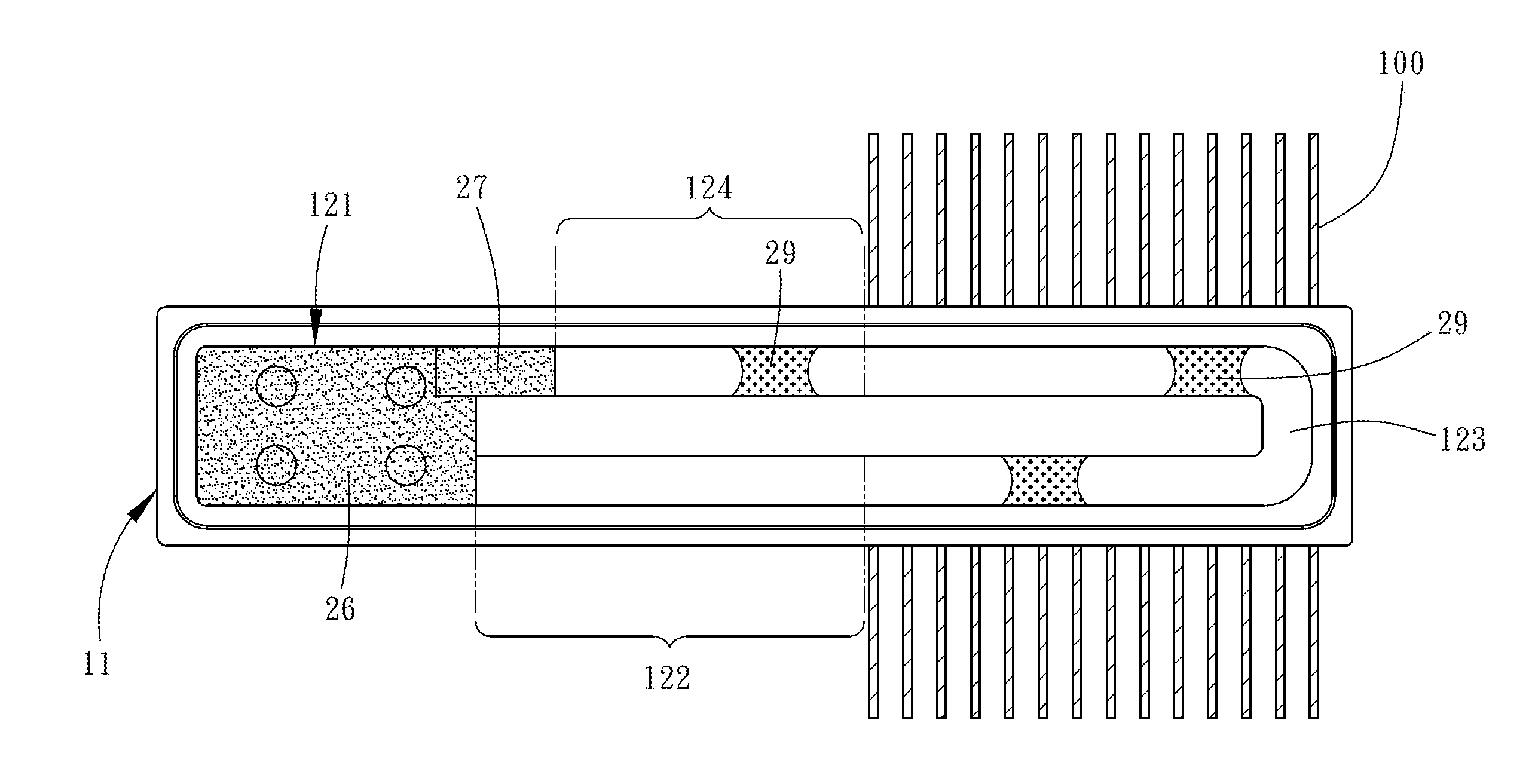
[0025] As shown in FIG. 5, before using the loop vapor chamber, a user adheres the base board 11 of the loop vapor chamber 10 to a target for heat dissipation (for example, a CPU (not shown) of a computer) such that the evaporation chamber 121 corresponds in position to the target for heat dissipation. A heat-dissipating unit 100 is disposed on the base board 11 and corresponds in position to the condensation channel 123. In this embodiment, the heat-dissipating unit 100 comprises a plurality of fins.
[0026] As shown in FIG. 5, during the usage of the loop vapor chamber, heat generated from the target for heat dissipation is transferred to the evaporation chamber 121, and thus the working fluid which adsorbs on the wick 26 in the evaporation chamber 121 evaporates into a gaseous working fluid which then spreads throughout the evaporation space. Afterward, the gaseous working fluid reaches the condensation channel 123 via the vapor channel 122. Then, the heat-dissipating unit 100 allows the heat to be dissipated by air such that the condensation channel 123 has a lower temperature than the evaporation chamber 121; hence, the gaseous working fluid in the condensation channel 123 cools down and condenses into droplets of a liquid working fluid. As a result, the droplets of the liquid working fluid attach to the inner wall of the condensation channel 123. As time passed, the resultant liquid working fluid in droplets becomes massive enough to occupy the condensation channel 123 fully to form fluid slugs 29 defined by the cross sections of the condensation channel 123. The gaseous working fluid exits the vapor channel 122 and enters the condensation channel 123 continuously and thus spontaneously generates a pressure difference. Under the pressure difference, the fluid slugs 29 move from the condensation channel 123 to the liquid channel 124 before arriving at the evaporation chamber 121 where the fluid slugs 29 adsorb on the space partition element 27 and then return to the wick 26. The aforesaid process recurs and thus guides heat out of the target for heat dissipation continuously, thereby performing heat dissipation well.
[0027] In the first preferred embodiment, the evaporation chamber 121 and the return path (composed of the vapor channel 122, the condensation channel 123 and the liquid channel 124) are integrally formed and disposed within the space hermetically sealed by the lid 21 and the base board 11; hence, the evaporation chamber 121 and the return path are collectively equivalent to an integral structure. The return path is free of any wick layer but still allows the working fluid to transit from a gaseous phase to a liquid phase and return to the evaporation chamber 121. With a wick layer being dispensed with, the return path further reduces the thickness requirement of the vapor chamber.
[0028] Referring to FIG. 6 and FIG. 7, a loop vapor chamber 30 in the second preferred embodiment of the present disclosure is substantially identical to its counterpart in the first preferred embodiment of the present disclosure except for its distinguishing technical features described below.
[0029] The base board 31 has two channel partition elements 34 (partition boards for exemplary purposes) disposed in the liquid channel 324. The two channel partition elements 34 extend from the liquid channel 324 into the condensation channel 323. Therefore, the two channel partition elements 34 partition the liquid channel 324 and the condensation channel 323 into three fluid slug channels 341 penetrating the liquid channel 324 and the condensation channel 323. The fluid slug channels 341 are of a smaller caliber than the vapor channel 322. The channel partition elements 34 are designed in such a manner that the fluid slug channels 341 are of a small caliber; hence, the working fluid droplets adsorbing on the condensation channel 323 are likely to merge and form fluid slugs 49 (shown in FIG. 7) defined by the cross sections of the fluid slug channels 341, respectively.
[0030] In the second preferred embodiment, the space partition element 47 (by contrast, in the first preferred embodiment, the space partition element 27 extends into the liquid channel 324) is made of solid metal, abuts against the wick 46 and the lid 41 from below and above, respectively, and separates the evaporation space 328 from the liquid channel 324.
[0031] The channel partition elements 34 are not necessarily in the number of two, but can be in the number of one or more than two in a variant embodiment. Hence, the number of the channel partition elements 34 is subject to changes as needed.
[0032] The other structures and achievable advantages in the second preferred embodiment are substantially identical to their counterparts in the first preferred embodiment and thus, for the sake of brevity, are not described again.
[0033] Referring to FIG. 8 and FIG. 9, a loop vapor chamber 50 in the third preferred embodiment of the present disclosure is substantially identical to its counterpart in the second preferred embodiment of the present disclosure except for its distinguishing technical features described below.
[0034] The wick 66 extends into the liquid channel 524 by a predetermined length. The space partition element 67 is disposed in the liquid channel and above a segment of the wick 66 (the segment of the wick 66 is located in the liquid channel 524 because of the extension of the wick 66). The space partition element 67 occupies the liquid channel 524 fully in terms of its cross section without blocking the segment of the wick 66 (the segment of the wick 66 is located in the liquid channel 524 because of the extension of the wick 66).
[0035] The two channel partition elements 54 extend into the vapor channel 522. The gaseous working fluid exits the evaporation space 528 and enters the vapor channel 522 smoothly.
[0036] Therefore, the space partition element 67 separates the evaporation space 528 and the liquid channel 524 effectively, whereas the liquid working fluid adsorbs on the segment of the wick 66 (the segment of the wick 66 is located in the liquid channel 524 because of the extension of the wick 66).
[0037] The other structural features and achievable advantages of the third embodiment are substantially identical to their counterparts in the second embodiment and thus, for the sake of brevity, are not described herein.
* * * * *
D00000
D00001
D00002
D00003
D00004
D00005
D00006
D00007
D00008
D00009
XML
uspto.report is an independent third-party trademark research tool that is not affiliated, endorsed, or sponsored by the United States Patent and Trademark Office (USPTO) or any other governmental organization. The information provided by uspto.report is based on publicly available data at the time of writing and is intended for informational purposes only.
While we strive to provide accurate and up-to-date information, we do not guarantee the accuracy, completeness, reliability, or suitability of the information displayed on this site. The use of this site is at your own risk. Any reliance you place on such information is therefore strictly at your own risk.
All official trademark data, including owner information, should be verified by visiting the official USPTO website at www.uspto.gov. This site is not intended to replace professional legal advice and should not be used as a substitute for consulting with a legal professional who is knowledgeable about trademark law.