Loop Vapor Chamber Conducive To Separation Of Liquid And Gas
TSENG; Chuan-Chi ; et al.
U.S. patent application number 16/042134 was filed with the patent office on 2019-11-07 for loop vapor chamber conducive to separation of liquid and gas. The applicant listed for this patent is TAI-SOL ELECTRONICS CO., LTD.. Invention is credited to Ming-Quan CUI, Wen-Ching LIAO, Chuan-Chi TSENG.
| Application Number | 20190339020 16/042134 |
| Document ID | / |
| Family ID | 68383846 |
| Filed Date | 2019-11-07 |


| United States Patent Application | 20190339020 |
| Kind Code | A1 |
| TSENG; Chuan-Chi ; et al. | November 7, 2019 |
LOOP VAPOR CHAMBER CONDUCIVE TO SEPARATION OF LIQUID AND GAS
Abstract
A loop vapor chamber conducive to separation of liquid and gas includes a base, an upper lid, a wick structure and a working fluid. The base includes a first recess, a second recess, a first extension channel and a second extension channel. The first recess and the second recess are in communication with each other through the first extension channel and the second extension channel. The upper lid is coupled to the base. The first recess, the second recess, the first extension channel and the second extension channel together form a closed space. The wick structure is disposed in the closed space and thus corresponds in position to the first recess, the second recess and the first extension channel.
| Inventors: | TSENG; Chuan-Chi; (TAIPEI CITY, TW) ; LIAO; Wen-Ching; (TAIPEI CITY, TW) ; CUI; Ming-Quan; (WUJIANG CITY, CN) | ||||||||||
| Applicant: |
|
||||||||||
|---|---|---|---|---|---|---|---|---|---|---|---|
| Family ID: | 68383846 | ||||||||||
| Appl. No.: | 16/042134 | ||||||||||
| Filed: | July 23, 2018 |
| Current U.S. Class: | 1/1 |
| Current CPC Class: | F28D 15/046 20130101; F28D 15/0233 20130101; F28D 15/0266 20130101; F28D 15/043 20130101 |
| International Class: | F28D 15/04 20060101 F28D015/04 |
Foreign Application Data
| Date | Code | Application Number |
|---|---|---|
| May 4, 2018 | TW | 107115225 |
Claims
1. A loop vapor chamber conducive to separation of liquid and gas, comprising: a base comprising a first recess, a second recess, a first extension channel and a second extension channel, wherein the first recess and the second recess are in communication with each other through the first extension channel and the second extension channel; an upper lid coupled to the base, wherein the first recess, the second recess, the first extension channel and the second extension channel together form a closed space; a wick structure disposed in the closed space and thus corresponding in position to the first recess, the second recess and the first extension channel; and a working fluid filling the closed space and contained in the wick structure.
2. The loop vapor chamber conducive to separation of liquid and gas according to claim 1, wherein bottom surfaces of the first recess, the second recess, the first extension channel and the second extension channel are formed on a same horizontal plane, and the upper lid is panel-shaped.
3. The loop vapor chamber conducive to separation of liquid and gas according to claim 1, wherein the first extension channel and the second extension channel are separated by a first predetermined distance.
4. The loop vapor chamber conducive to separation of liquid and gas according to claim 1, wherein rims of the first recess and the second recess define a first side, a second side, a third side and a fourth side respectively and sequentially, with the first extension channel connected to the third side of the first recess and the first side of the second recess, and the second extension channel connected to the third side of the first recess and the first side of the second recess.
5. The loop vapor chamber conducive to separation of liquid and gas according to claim 1, wherein rims of the first recess and the second recess define a first side, a second side, a third side and a fourth side respectively and sequentially, with the first extension channel connected to the second side of the first recess and the second side of the second recess, and the second extension channel connected to the fourth side of the first recess and the fourth side of the second recess.
6. The loop vapor chamber conducive to separation of liquid and gas according to claim 1, wherein rims of the first recess and the second recess define a first side, a second side, a third side and a fourth side respectively and sequentially, with the first extension channel connected to the third side of the first recess and the first side of the second recess, and the second extension channel connected to the fourth side of the first recess and the fourth side of the second recess.
7. The loop vapor chamber conducive to separation of liquid and gas according to claim 1, wherein the wick structure comprises a first wick layer, a second wick layer, a third wick layer, a fourth wick layer and a wick, with the first wick layer formed at the upper lid and disposed at a corresponding portion of the first recess, the first wick layer not affecting communication between the first recess, the first extension channel and the second extension channel, with the second wick layer formed at the upper lid and disposed at a corresponding portion of the second recess, the second wick layer not affecting communication between the second recess, the first extension channel and the second extension channel, with the third wick layer formed at the base and disposed in the first recess, the third wick layer not affecting communication between the first recess, the first extension channel and the second extension channel, with the fourth wick layer formed at the base and disposed in the second recess, the fourth wick layer not affecting communication between the second recess, the first extension channel and the second extension channel, with the wick disposed in the first extension channel to fill at least a portion of the first extension channel fully.
8. The loop vapor chamber conducive to separation of liquid and gas according to claim 7, wherein the first wick layer, the second wick layer, the third wick layer and the fourth wick layer are made of copper powder or mesh, and the wick is made of copper powder or fibers.
9. The loop vapor chamber conducive to separation of liquid and gas according to claim 7, wherein the wick extends across the first recess and the second recess.
10. The loop vapor chamber conducive to separation of liquid and gas according to claim 7, wherein a plurality of raised portions is disposed between the first recess, the second recess and the upper lid corresponding in position thereto, abuttingly disposed between the first wick layer and the third wick layer and between the second wick layer and the fourth wick layer, and separated from each other by a second predetermined distance.
11. The loop vapor chamber conducive to separation of liquid and gas according to claim 10, wherein the raised portions are made of a wick material or solid metal lumps.
12. The loop vapor chamber conducive to separation of liquid and gas according to claim 10, wherein the raised portions are cylindrical.
13. The loop vapor chamber conducive to separation of liquid and gas according to claim 10, wherein the raised portions are arranged in a matrix.
14. The loop vapor chamber conducive to separation of liquid and gas according to claim 1, wherein bottom surfaces of the first recess, the second recess, the first extension channel and the second extension channel are formed on different horizontal planes, respectively.
Description
BACKGROUND OF THE INVENTION
1. Technical Field
[0001] The present disclosure relates to vapor chambers and, more particularly, to a loop vapor chamber conducive to separation of liquid and gas.
2. Description of Related Art
[0002] Regarding conventional loop vapor chambers, US 2016/0128234A1 discloses a cooling device and an electronic apparatus. The cooling device essentially comprises two plates, namely a heat receiving plate and a heat radiation plate, an air tube, and a liquid tube. The air tube and the liquid tube together connect the heat receiving plate and the heat radiation plate to form a loop vapor chamber conducive to separation of liquid and gas. The air tube and the liquid tube are connected between the heat receiving plate and the heat radiation plate by a welding process in order to form the conventional loop vapor chamber.
[0003] However, the welding process not only leads to lower product yield, but also lessens the structural strength at a welding point. The welding point is likely to get damaged because of a collision or long use, thereby ending up with a short service life.
[0004] Therefore, it is important to reduce the welding process in order to enhance product yield effectively.
[0005] Furthermore, the reduction of the welding process is effective in increasing the structural strength at the welding point and thus extending the service life.
BRIEF SUMMARY OF THE INVENTION
[0006] It is an objective of the present disclosure to provide a loop vapor chamber conducive to separation of liquid and gas with a view to reducing its welding process and thereby enhancing its product yield.
[0007] Another objective of the present disclosure is to provide a loop vapor chamber conducive to separation of liquid and gas with a view to reducing its welding process and thereby extending its service life.
[0008] In order to achieve the above and other objectives, the present disclosure provides a loop vapor chamber conducive to separation of liquid and gas, comprising: a base comprising a first recess, a second recess, a first extension channel and a second extension channel, wherein the first recess and the second recess are in communication with each other through the first extension channel and the second extension channel; an upper lid coupled to the base, wherein the first recess, the second recess, the first extension channel and the second extension channel together form a closed space; a wick structure disposed in the closed space and thus corresponding in position to the first recess, the second recess and the first extension channel; and a working fluid filling the closed space and contained in the wick structure.
[0009] Therefore, according to the present disclosure, a loop vapor chamber conducive to separation of liquid and gas is effective in reducing its welding process and thereby enhancing its product yield.
[0010] Furthermore, according to the present disclosure, a loop vapor chamber conducive to separation of liquid and gas is effective in reducing its welding process and thus increasing the structural strength at the welding point, thereby extending its service life.
BRIEF DESCRIPTION OF THE SEVERAL VIEWS OF THE DRAWINGS
[0011] FIG. 1 is a perspective view of a loop vapor chamber according to the first embodiment of the present disclosure;
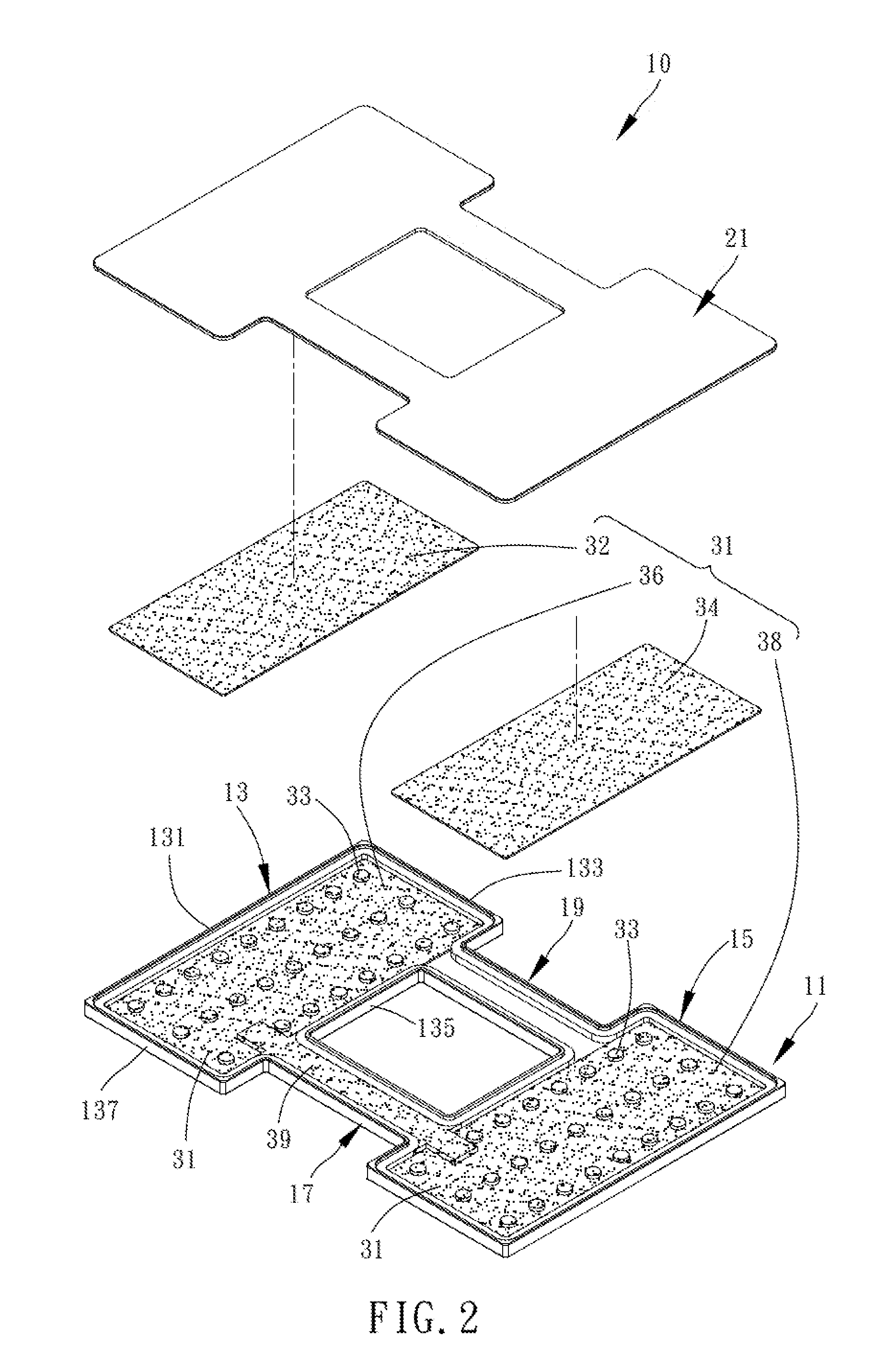
[0012] FIG. 2 is the first exploded view of the loop vapor chamber according to the first embodiment of the present disclosure;
[0013] FIG. 3 is a cross-sectional view of the loop vapor chamber taken along line 3-3 of FIG. 1;
[0014] FIG. 4 is a cross-sectional view of the loop vapor chamber taken along line 4-4 of FIG. 1;
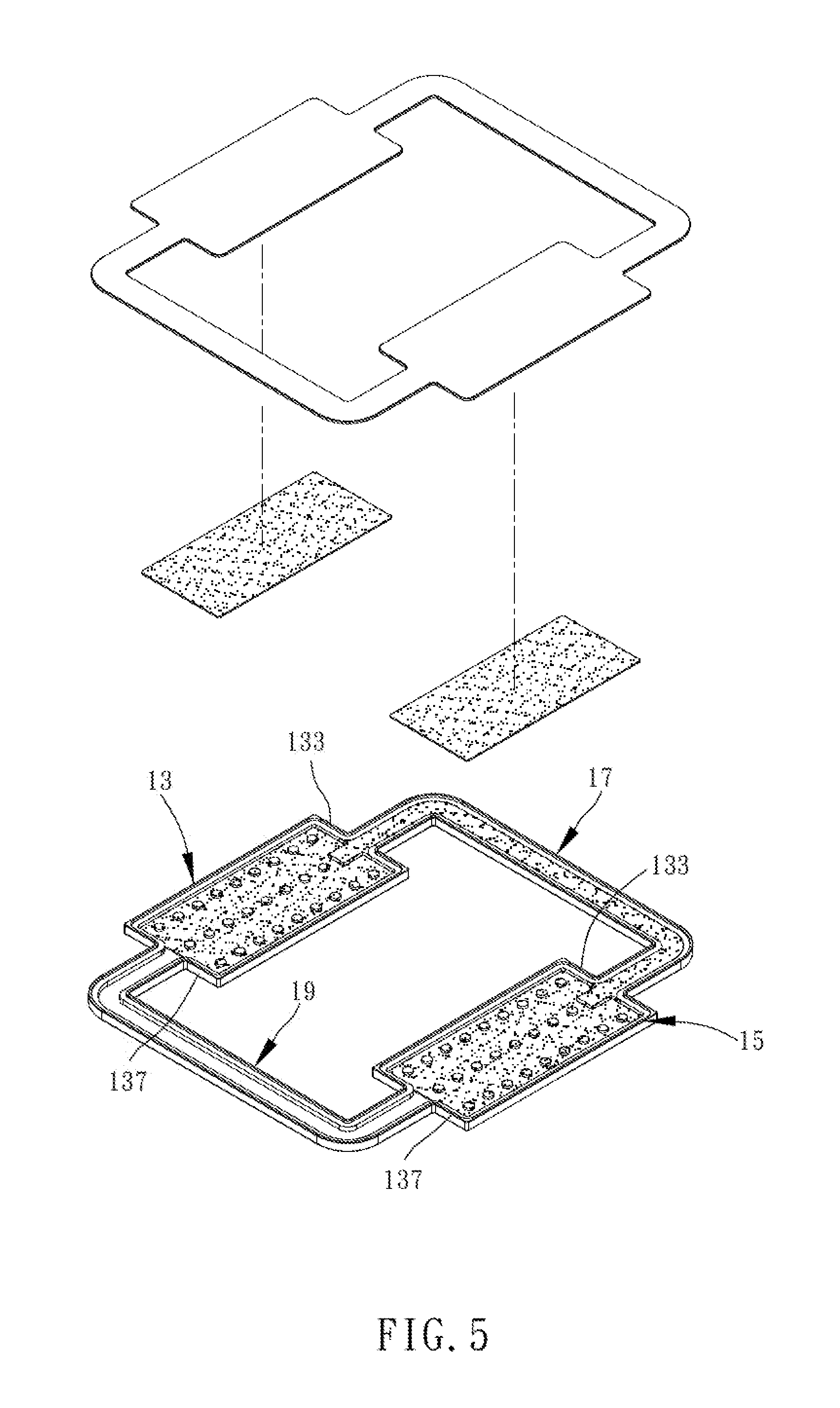
[0015] FIG. 5 is the second exploded view of the loop vapor chamber according to the first embodiment of the present disclosure, showing that a first extension channel and a second extension channel are located at different positions, respectively;
[0016] FIG. 6 is the third exploded view of the loop vapor chamber according to the first embodiment of the present disclosure, showing that the first extension channel and the second extension channel are located at different positions, respectively;
[0017] FIG. 7 is the fourth exploded view of the loop vapor chamber according to the first embodiment of the present disclosure, showing that bottom surfaces of a first recess, a second recess, the first extension channel and the second extension channel are formed on different horizontal planes, respectively;
[0018] FIG. 8 is a partial front view of FIG. 7, showing that the bottom surfaces of the first recess, the second recess, the first extension channel and the second extension channel are formed on different horizontal planes, respectively;
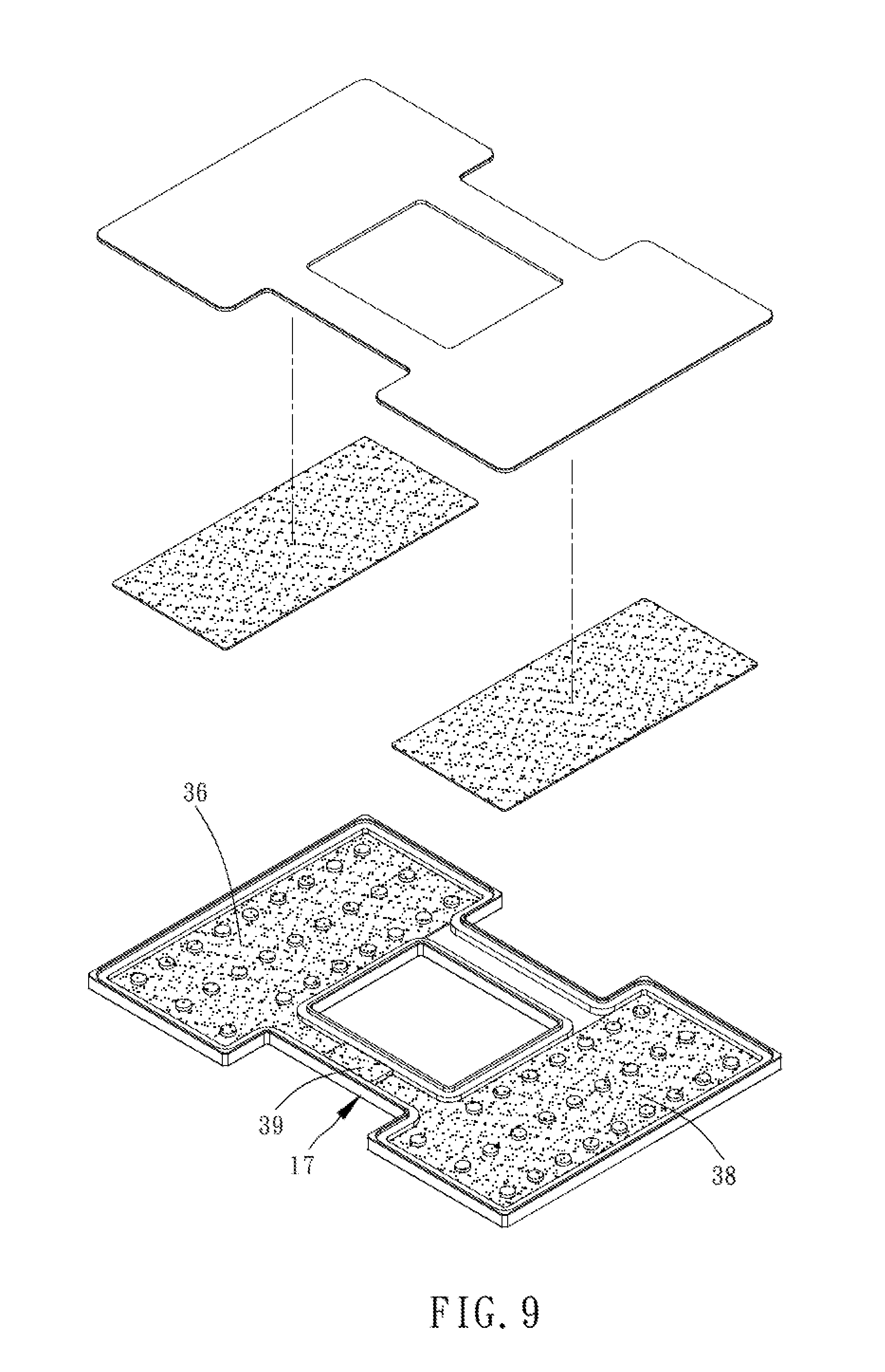
[0019] FIG. 9 is the fifth exploded view of the loop vapor chamber according to the first embodiment of the present disclosure, showing that a portion of the first extension channel is filled fully with a wick;
[0020] FIG. 10 is an exploded view of the loop vapor chamber according to the second embodiment of the present disclosure; and
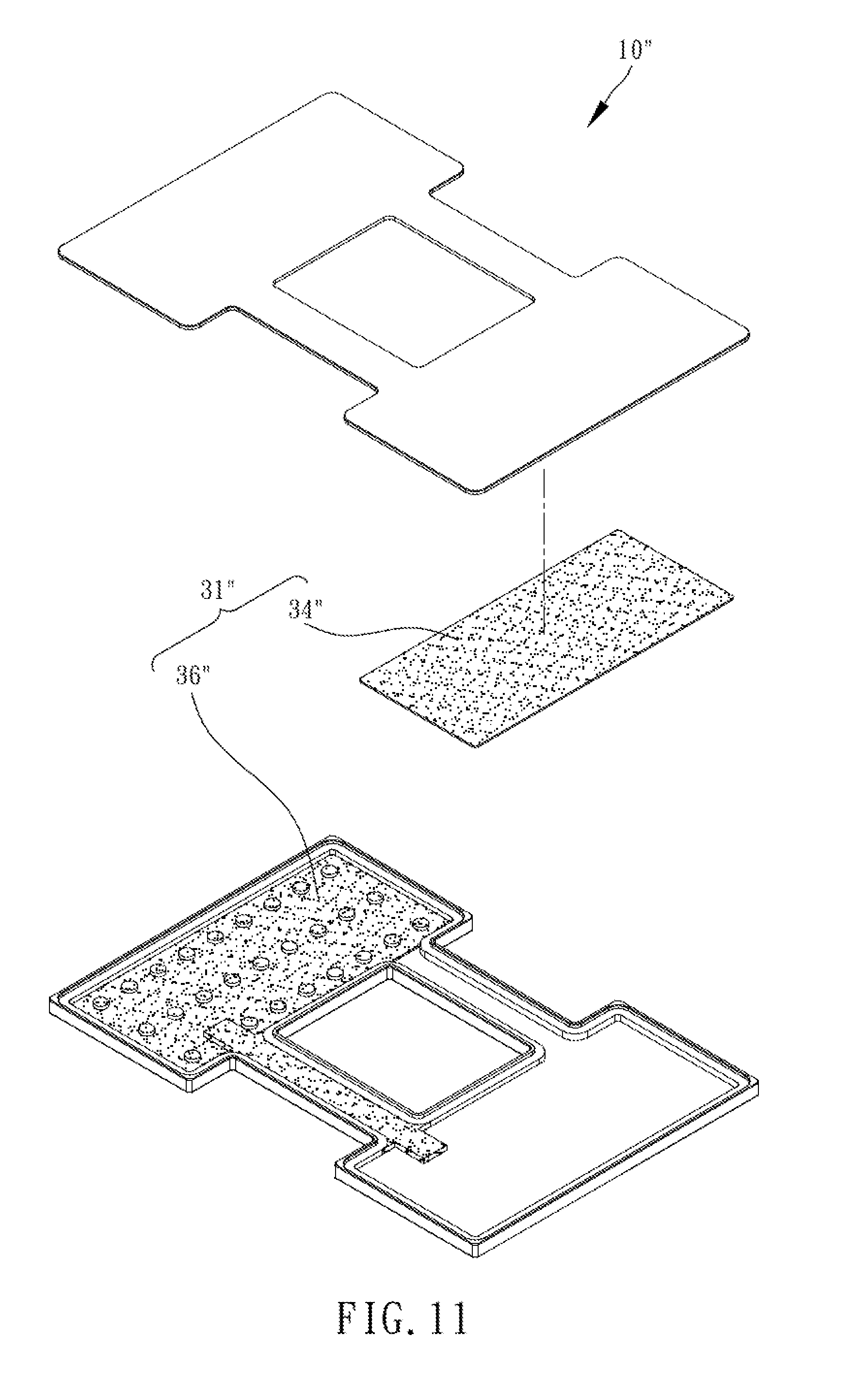
[0021] FIG. 11 is an exploded view of the loop vapor chamber according to the third embodiment of the present disclosure.
DETAILED DESCRIPTION OF THE INVENTION
[0022] Technical features of the present disclosure are illustrated by the first embodiment, depicted by drawings, and described below.
[0023] Referring to FIG. 1 through FIG. 4, the first embodiment of the present disclosure provides a loop vapor chamber 10 conducive to separation of liquid and gas, which essentially comprises a base 11, an upper lid 21, a wick structure 31 and a working fluid (the working fluid is not shown in the diagrams, because it is well-known among persons skilled in the art).
[0024] The base 11 comprises a first recess 13, a second recess 15, a first extension channel 17 and a second extension channel 19. The first recess 13 and the second recess 15 are in communication with each other through the first extension channel 17 and the second extension channel 19. In this embodiment, as shown in FIG. 1 through FIG. 4, the first extension channel 17 and the second extension channel 19 are separated by a first predetermined distance. The rims of the first recess 13 and the second recess 15 define a first side 131, a second side 133, a third side 135 and a fourth side 137 respectively and sequentially. The first extension channel 17 is connected to the third side 135 of the first recess 13 and the first side 131 of the second recess 15. The second extension channel 19 is connected to the third side 135 of the first recess 13 and the first side 131 of the second recess 15.
[0025] The upper lid 21 is coupled to the base 11. The first recess 13, the second recess 15, the first extension channel 17 and the second extension channel 19 together form a closed space 18. In this embodiment, bottom surfaces of the first recess 13, the second recess 15, the first extension channel 17 and the second extension channel 19 are formed on the same horizontal plane. The upper lid 21 is panel-shaped and corresponds in outline to the first recess 13, the second recess 15, the first extension channel 17 and the second extension channel 19.
[0026] In this embodiment, the wick structure 31 comprises a first wick layer 32, a second wick layer 34, a third wick layer 36, a fourth wick layer 38 and a wick 39.
[0027] The first wick layer 32 is made of sintered copper powder. The first wick layer 32 is formed at the upper lid 21 and disposed at a portion of the first recess 13. The portion of the first recess 13 faces the upper lid 21. The first wick layer 32 does not affect the communication between the first recess 13, the first extension channel 17 and the second extension channel 19.
[0028] The second wick layer 34 is made of sintered copper powder. The second wick layer 34 is formed at the upper lid 21 and disposed at a portion of the second recess 15. The portion of the second recess 15 faces the upper lid 21. The second wick layer 34 does not affect communication between the second recess 15, the first extension channel 17 and the second extension channel 19.
[0029] The third wick layer 36 is made of sintered copper powder. The third wick layer 36 is formed at the base 11 and disposed in the first recess 13. The third wick layer 36 does not affect communication between the first recess 13, the first extension channel 17 and the second extension channel 19.
[0030] The fourth wick layer 38 is made of sintered copper powder. The fourth wick layer 38 is formed at the base 11 and disposed in the second recess 15. The fourth wick layer 38 does not affect communication between the second recess 15, the first extension channel 17 and the second extension channel 19.
[0031] The wick 39 is disposed in the first extension channel 17, fills the first extension channel 17 fully, and is in contact with the first, second, third and fourth wick layers 32, 34, 36, 38. In this embodiment, the wick 39 is made of sintered copper powder and extends across the first recess 13 and the second recess 15 such that the wick 39 has maximal contact area with the first, second, third and fourth wick layers 32, 34, 36, 38, so as to increase the flow rate of the working fluid and enhance heat dissipation efficiency.
[0032] The first wick layer 32, the second wick layer 34, the third wick layer 36 and the fourth wick layer 38 can be made of any other appropriate material, such as mesh. Alternatively, the first and second wick layers 32, 34 are made of sintered copper powder, whereas the third and fourth wick layers 36, 38 are made of mesh. Alternatively, the first and second wick layers 32, 34 are made of mesh, whereas the third and fourth wick layers 36, 38 are made of sintered copper powder. The wick 39 may also be made of fibers. Therefore, the first, second, third and fourth wick layers 32, 34, 36, 38 and the wick 39 are not necessarily made of sintered copper powder.
[0033] A plurality of raised portions 33 is disposed between the first recess 13, the second recess 15 and the upper lid 21 corresponding in position thereto. The raised portions 33 are each made of a wick material. In this embodiment, the raised portions 33 are each made of sintered copper powder. The raised portions 33 are each not only abuttingly disposed between the first wick layer 32 and the third wick layer 36 but also abuttingly disposed between the second wick layer 34 and the fourth wick layer 38. The raised portions 33 are separated from each other by a second predetermined distance. The raised portions 33 are cylindrical and arranged in a matrix. Therefore, the working fluid has high delivery efficiency, rendering the present disclosure highly patentable.
[0034] The raised portions 33 may also be post-shaped, for example, be in the form of triangular posts or square posts. The raised portions 33 may also be arranged in an irregular pattern. If the first, second, third and fourth wick layers 32, 34, 36, 38 are made of sintered copper powder, the raised portions 33 can be made of solid metal lumps; hence, the working fluid not only escapes from the first, second, third and fourth wick layers 32, 34, 36, 38 readily, but can also be delivered between the first wick layer 32 and the third wick layer 36 or between the second wick layer 34 and the fourth wick layer 38 without affecting circulation of the working fluid, not to mention rendering the present disclosure highly patentable. Therefore, implementation of the plurality of raised portions 33 is not restricted to this embodiment. The present disclosure can dispense with the plurality of raised portions 33, unless the patentability of the present disclosure is an issue. Therefore, the plurality of raised portions 33 is not a required element of the present disclosure.
[0035] The working fluid fills the closed space 18 and is contained in the wick structure 31.
[0036] Referring to FIG. 5, in the first embodiment, it is also feasible for the first extension channel 17 to be connected to the second side 133 of the first recess 13 and the second side 133 of the second recess 15, and for the second extension channel 19 to be connected to the fourth side 137 of the first recess 13 and the fourth side 137 of the second recess 15.
[0037] Referring to FIG. 6, the first extension channel 17 is connected to the third side 135 of the first recess 13 and the first side 131 of the second recess 15, whereas the second extension channel 19 is connected to the fourth side 137 of the first recess 13 and the fourth side 137 of the second recess 15.
[0038] Therefore, the positions of the first extension channel 17 and the second extension channel 19 disposed between the first recess 13 and the second recess 15 as well as the channel-shape of the first extension channel 17 and the second extension channel 19 are subject to changes as needed. Therefore, the positions of the first and second extension channels 17, 19 connected to the first and second recesses 13, 15 are not restricted to this embodiment.
[0039] As shown in FIG. 7 and FIG. 8, bottom surfaces of the first recess 13, the second recess 15, the first extension channel 17 and the second extension channel 19 are formed on different horizontal planes, respectively, whereas the upper lid 21 is non-panel shaped (for example, convoluted (not shown) in such a manner to fit the bottom surfaces of the first recess 13, the second recess 15, the first extension channel 17 or the second extension channel 19). Therefore, implementation of the upper lid 21 and the bottom surfaces of the first recess 13, the second recess 15, the first extension channel 17 and the second extension channel 19 is not restricted to this embodiment.
[0040] Referring to FIG. 9, although just a portion of the first extension channel 17 is fully filled with the wick 39, the circulation of the working fluid will be efficient enough to enable effective heat dissipation, provided that the third wick layer 36 and the fourth wick layer 38 are still in contact with the wick 39. Therefore, the wick 39 is not restricted to this embodiment.
[0041] Structural features of the first embodiment are described above. Operation-related features of the first embodiment are described below.
[0042] Referring to FIG. 1 through FIG. 3, the loop vapor chamber of the present disclosure operates in conjunction with a heat source and a heat dissipating apparatus (not shown). In this embodiment, the heat source is placed at the upper lid 21 corresponding in position to the first recess 13, whereas the heat dissipating apparatus is placed at the upper lid 21 corresponding in position to the second recess 15, for exemplary purposes. When the heat source begins to generate heat, the working fluid of the first wick layer 32 evaporates within the first recess 13, and thus the gaseous the working fluid passes through the second extension channel 19 to thereby enter the second recess 15. After coming into contact with the upper lid 21 having the heat dissipating apparatus and thus being cooled down, the gaseous working fluid condenses into the liquid working fluid and becomes contained in the second wick layer 34 of the second recess 15. Then, the liquid working fluid is delivered to the fourth wick layer 38 in the second recess 15 by the raised portions 33 of the second recess 15. The liquid working fluid passes through the first extension channel 17 because of the wick 39 and then reaches the third wick layer 36 in the first recess 13. Finally, the liquid working fluid contained in the third wick layer 36 in the first recess 13 is delivered by the raised portions 33 in the first recess 13 to the first wick layer 32, thereby achieving cooling and re-circulation.
[0043] Therefore, the present disclosure is effective in reducing its welding process and thereby enhancing its product yield.
[0044] Therefore, the present disclosure is effective in reducing its welding process and thereby extending its service life.
[0045] Referring to FIG. 10, the second embodiment is substantially identical to the first embodiment in structures and advantages except for its distinguishing technical features described below.
[0046] The second embodiment of the present disclosure provides a loop vapor chamber 10' conducive to separation of liquid and gas. The base 11' has two said first extension channels 17' and two said second extension channels 19'. In this embodiment, the two said first extension channels 17' and two said second extension channels 19' are disposed between the third side 135' of the first recess 13' and the first side 131' of the second recess 15', for exemplary purposes, to increase the flow rate of the working fluid returning and thus enhance heat dissipation efficiency. In a variant embodiment, the quantity and connection positions of the first extension channels 17' and the second extension channels 19' are adjustable. Therefore, implementation of the first extension channels 17' and the second extension channels 19' is not restricted to this embodiment.
[0047] Therefore, the second embodiment of the present disclosure is effective in increasing the flow rate of the working fluid returning and thus enhancing heat dissipation efficiency.
[0048] The other structural features and advantages of the second embodiment are substantially identical to those of the first embodiment and thus, for the sake of brevity, are not described herein.
[0049] Referring to FIG. 11, the structural features and advantages of the third embodiment are substantially identical to those of the first embodiment and thus, for the sake of brevity, are not described herein.
[0050] The third embodiment of the present disclosure provides a loop vapor chamber 10'' conducive to separation of liquid and gas. The wick structure 31'' comprises a second wick layer 34'' and a third wick layer 36''. The third embodiment dispenses with the first wick layer 32 and the fourth wick layer 38 shown in FIG. 2 of the first embodiment and still enables circulation of the working fluid. Therefore, the wick structure 31'' is subject to changes and thus is not restricted to this embodiment.
[0051] The other structural features and advantages of the third embodiment are substantially identical to those of the first embodiment and thus, for the sake of brevity, are not described herein.
* * * * *
D00000
D00001
D00002
D00003
D00004
D00005
D00006
D00007
D00008
D00009
D00010
XML
uspto.report is an independent third-party trademark research tool that is not affiliated, endorsed, or sponsored by the United States Patent and Trademark Office (USPTO) or any other governmental organization. The information provided by uspto.report is based on publicly available data at the time of writing and is intended for informational purposes only.
While we strive to provide accurate and up-to-date information, we do not guarantee the accuracy, completeness, reliability, or suitability of the information displayed on this site. The use of this site is at your own risk. Any reliance you place on such information is therefore strictly at your own risk.
All official trademark data, including owner information, should be verified by visiting the official USPTO website at www.uspto.gov. This site is not intended to replace professional legal advice and should not be used as a substitute for consulting with a legal professional who is knowledgeable about trademark law.