Heat exchanger for exchanging heat of fluids having different temperatures
Tarapoom; Nattapong ; et al.
U.S. patent application number 16/473603 was filed with the patent office on 2019-11-07 for heat exchanger for exchanging heat of fluids having different temperatures. The applicant listed for this patent is PTT Global Chemical Public Company Limited, PTT Public Company Limited. Invention is credited to Rungroj Chuvaree, Supawish Klannark, Nichaporn Sirimungkalakul, Kawisra Sompech, Thana Sornchamni, Wannawijit Srithammarat, Nattapong Tarapoom, Treerat Vacharanukrauh.
| Application Number | 20190339018 16/473603 |
| Document ID | / |
| Family ID | 62710367 |
| Filed Date | 2019-11-07 |


| United States Patent Application | 20190339018 |
| Kind Code | A1 |
| Tarapoom; Nattapong ; et al. | November 7, 2019 |
Heat exchanger for exchanging heat of fluids having different temperatures
Abstract
A heat exchanger for exchanging heat of fluids having different temperatures, comprising: at least one smooth heat exchanging plate; at least one high temperature heat exchanging plate; and at least one low temperature heat exchanging plate stacked in an alternating sequence, wherein an inlet of high temperature fluid and an outlet of high temperature fluid are disposed in order to pass a high temperature fluid through each said high temperature heat exchanging plate, and an inlet of low temperature fluid and an outlet of low temperature fluid are disposed in order to pass a low temperature fluid through each said low temperature heat exchanging plate, wherein said high temperature heat exchanging plate and said low temperature the heat exchanging plate comprising a high temperature channel and a low temperature channel, wherein said channels have a length extending in a flow direction of said fluids and a side wall of each said channel has a symmetric wavy pattern with the center line of said channel.
| Inventors: | Tarapoom; Nattapong; (Bangkok, TH) ; Vacharanukrauh; Treerat; (Bangkok, TH) ; Sompech; Kawisra; (Bangkok, TH) ; Srithammarat; Wannawijit; (Bangkok, TH) ; Klannark; Supawish; (Bangkok, TH) ; Sirimungkalakul; Nichaporn; (Bangkok, TH) ; Sornchamni; Thana; (Bangkok, TH) ; Chuvaree; Rungroj; (Bangkok, TH) | ||||||||||
| Applicant: |
|
||||||||||
|---|---|---|---|---|---|---|---|---|---|---|---|
| Family ID: | 62710367 | ||||||||||
| Appl. No.: | 16/473603 | ||||||||||
| Filed: | December 21, 2017 | ||||||||||
| PCT Filed: | December 21, 2017 | ||||||||||
| PCT NO: | PCT/TH2017/000089 | ||||||||||
| 371 Date: | June 25, 2019 |
| Current U.S. Class: | 1/1 |
| Current CPC Class: | F28F 2260/02 20130101; F28F 3/025 20130101; F28F 3/046 20130101; F28D 9/0037 20130101; F28D 2021/0022 20130101; F28D 9/0062 20130101; F28D 9/0068 20130101 |
| International Class: | F28D 9/00 20060101 F28D009/00; F28F 3/02 20060101 F28F003/02 |
Foreign Application Data
| Date | Code | Application Number |
|---|---|---|
| Dec 26, 2016 | TH | 1601007738 |
Claims
1. A heat exchanger for exchanging heat of fluids having different temperatures comprising: at least one flat heat exchanging plate (12); at least one high temperature heat exchanging plate (14); and at least one low temperature heat exchanging plate (16) stacked in an alternating sequence, wherein an inlet of high temperature fluid (18a) and an outlet of high temperature fluid (20a) are disposed in order to pass a high temperature fluid through each said high temperature heat exchanging plate (14), and an inlet of low temperature fluid (18b) and an outlet of low temperature fluid (20b) are disposed in order to pass a low temperature fluid through each said low temperature heat exchanging plate (16); characterized in that said high temperature heat exchanging plate (14) comprising a high temperature channel (15) and said low temperature heat exchanging plate (16) comprising a low temperature channel (17), wherein said channels have a length extending in a flow direction of said fluids and a side wall of each said channel has a symmetric wavy pattern with a center line of said channel as a symmetric axis.
2. The heat exchanger according to claim 1, wherein the high temperature channel (15) and the low temperature channel (17) have an average width (y) in a range of 100 to 5,000 .mu.m and a curve length (x) and a curve radius (r) according to x.ltoreq.2r, wherein x is in a range of 100 to 100,000 .mu.m.
3. The heat exchanger according to claim 1, wherein the high temperature channel (15) and the low temperature channel (17) have an average width (y) in the range of 100 to 3,000 .mu.m, a curve length (x) in the range of 1,000 to 3,000 .mu.m, and a curve radius (r) in the range of 2,000 to 5,000 .mu.m.
4. The heat exchanger according to claim 1, wherein the high temperature channel (15) and the low temperature channel (17) have a depth in a range of 10 to 2,000 .mu.m according to a plane defined by the top of each high temperature heat exchanging plate (14) and each low temperature heat exchanging plate (16).
5. The heat exchanger according to claim 4, wherein the high temperature channel (15) and the low temperature channel (17) have the depth in a range of 500 to 1,500 .mu.m according to the plane defined by the top of each high temperature heat exchanging plate (14) and each low temperature heat exchanging plate (16).
6. The heat exchanger according to claim 4, wherein the high temperature heat exchanging plate (14) and the low temperature heat exchanging plate (16) are arranged in a direction such that the high temperature channel (15) and the low temperature channel (17) are oriented in alternate configuration.
7. The heat exchanger according to claim 1, wherein the flat heat exchanging plate (12), the high temperature heat exchanging plate (14), and the low temperature heat exchanging plate (16) have a thickness in a range of 10 to 10,000 .mu.m.
8. The heat exchanger according to claim 7, wherein the flat heat exchanging plate (12), the high temperature heat exchanging plate (14), and the low temperature heat exchanging plate (16) have the thickness in the range of 100 to 2,000 .mu.m.
9. The heat exchanger according to claim 1, wherein the inlet of high temperature fluid (18a) and the inlet of low temperature fluid (18b) are disposed in the opposite side of the heat exchanger in order to form counter-flow of fluids having different temperatures.
10. The heat exchanger according to claim 1, wherein said fluids have a temperature difference at least 1.degree. C.
11. The heat exchanger according to claim 10, wherein said fluids have the temperature difference at least 10.degree. C.
Description
TECHNICAL FIELD
[0001] Chemical engineering relates to a heat exchanger for exchanging heat of fluids having different temperatures.
BACKGROUND OF THE INVENTION
[0002] Until present, there have been reports on the development of microchannel heat exchanger. When compared to the normal size channels, the microchannels provide a higher heat transfer performance than normal heat exchanger, such as a shell and a tube heat exchanger and a plate and a frame heat exchanger. This is because the flow in microchannels can transfer heat from a channel wall into fluid faster, fluids in each channel have similar flow cross section temperatures, a heat transfer surface area is higher than normal channel at the same volume, and a pressure drop in the channel is relatively low. However, the microchannels have some disadvantages that lead to limitation for application. For example, it is easily to be clogged because the channel is narrow. Especially, when being used for heat exchanging of fluids having highly different pressure, the permanent deforming can be happened.
[0003] It is known that the character of the channel of the heat exchanger is important to the heat transfer performance and the overall strength of the heat exchanger. In addition, the character of the channel is a parameter to indicate the possibility in fabrication and the arrangement of the channel together. Therefore, there have been attempts continuously to develop the character of the channel in order to increase the performance of the heat exchanger and overcome the limitations previously said.
[0004] US20040031592 disclosed the heat exchanger comprising microchannel for the heat exchanging of three or more fluid streams, wherein the wall of said channel was flat with fins disposed in order to increase the heat changing surface area. However, the installation of said fins increased a fouling rate inside the heat exchanger. Therefore, this reduced the heat transfer performance and increased the pressure drop of the heat exchanger. Moreover, said design might have a problem when using with high pressure fluid, leading to a limitation.
[0005] U.S. Pat. No. 4,516,632 disclosed the microchannel heat exchanger comprising the slotted heat exchanging sheets and unslotted heat exchanger sheets stacked in an alternating sequence, wherein the slotted heat exchanging sheet was placed in 90 degree with respect to one another in an alternating sequence in order to form a cross-flow configuration of fluids having different temperatures. Nevertheless, said flow configuration did not give a high heat exchanging performance.
[0006] EP1875959 disclosed the forming process of an emulsion with the installation of the heat exchanger comprising the microchannel heat exchanging plate stacked in an alternating sequence, wherein said channel was designed like a snake shape. This made two flowing patterns in said channel: a counter-current and a co-current. However, said channel design leads to easily clogging of the contaminants and was more difficult to clean comparing to the one flow direction path from one side to another side.
[0007] U.S. Pat. No. 8,858,159 disclosed a gas turbine comprising cooling channels for the low temperature air to flow pass and reduce heat of blades in the gas turbine, wherein said cooling channels were equipped with curved in and out ribs and the pedestals between each pair of ribs in order to increase the heat transfer performance. However, the character of said pedestals between each pair of ribs might increase the pressure drop of the heat exchanger which was the limitation when applying to the heat transfer between fluids with highly different pressure or fluids with high viscosity.
[0008] US20100314088 disclosed the heat exchanger comprising plates consisting of micrcochannels stacked in an alternating sequence. Said plates were designed to be curved and said microchannels were set into non-symmetric wavy form making parallel channel along the flow direction of fluids. The total length of direct portion and curve portion was set to be constant. However, said patent did not disclose the suitable parameters of said wavy channel such as width size, curve radius, etc.
[0009] From all above, this invention aims to provide the heat exchanger for exchanging heat of fluids having different temperatures, especially to increase the heat transfer performance of said fluids and decrease problems related to the heat exchanger for exchanging heat of fluids having highly different pressures.
SUMMARY OF INVENTION
[0010] This invention aims to provide the heat exchanger for exchanging heat of fluids having different temperatures, especially to increase the heat exchanging performance of said fluids having different temperatures and decrease problems related to the heat exchanger for exchanging heat of fluids having highly different pressures.
[0011] In one aspect of the invention, this invention discloses the heat exchanger for exchanging heat of fluids having different temperatures, comprising: at least one flat heat exchanging plate; at least one high temperature heat exchanging plate; and at least one low temperature heat exchanging plate stacked in an alternating sequence, wherein an inlet of high temperature fluid and an outlet of high temperature fluid are disposed in order to pass the high temperature fluid through each said high temperature heat exchanging plate, and an inlet of an low temperature fluid and an outlet of low temperature fluid are disposed in order to pass the low temperature fluid through each said low temperature heat exchanging plate, wherein said high temperature heat exchanging plate and said low temperature heat exchanging plate comprising the high temperature channel and the low temperature channel, wherein said channels have a length extending in a flow direction of said fluids and a side wall of each said channel has a symmetric wavy pattern with, a center line of each said channel.
BRIEF DESCRIPTION OF THE DRAWINGS
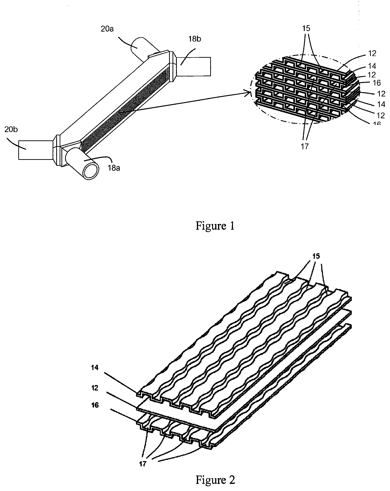
[0012] FIG. 1 shows one aspect of the heat exchanger according to the present invention.
[0013] FIG. 2 shows one aspect of the arrangement of the heat exchanging plate of the heat exchanger according to the present invention.
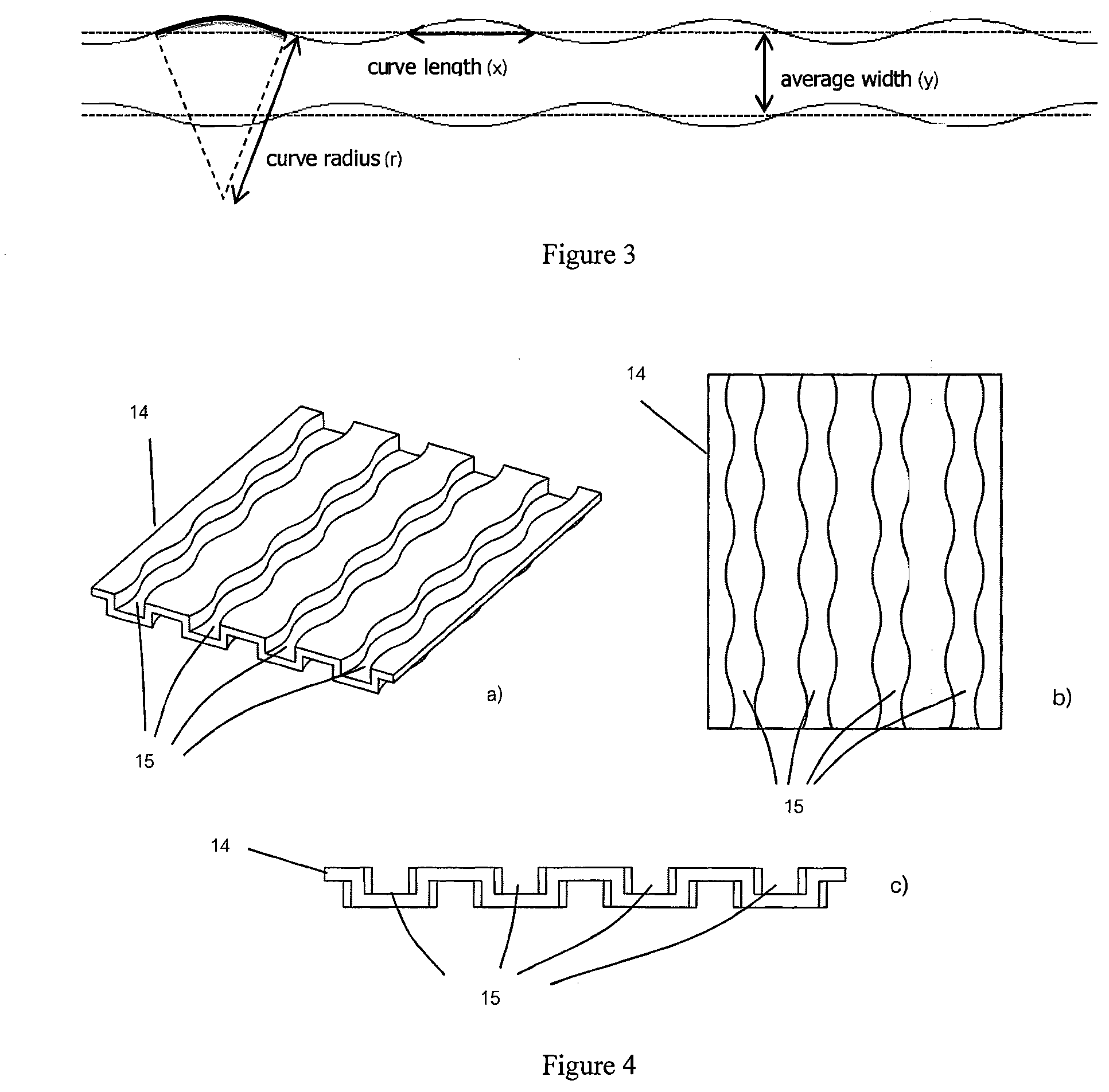
[0014] FIG. 3 shows one aspect of each high temperature channel and each high temperature channel of the heat exchanger according to the present invention.
[0015] FIG. 4 shows one aspect of the high temperature heat exchanging plate and the low temperature heat exchanging plate of the heat exchanger according to the present invention from a) isometric, b) top, and c) front views.
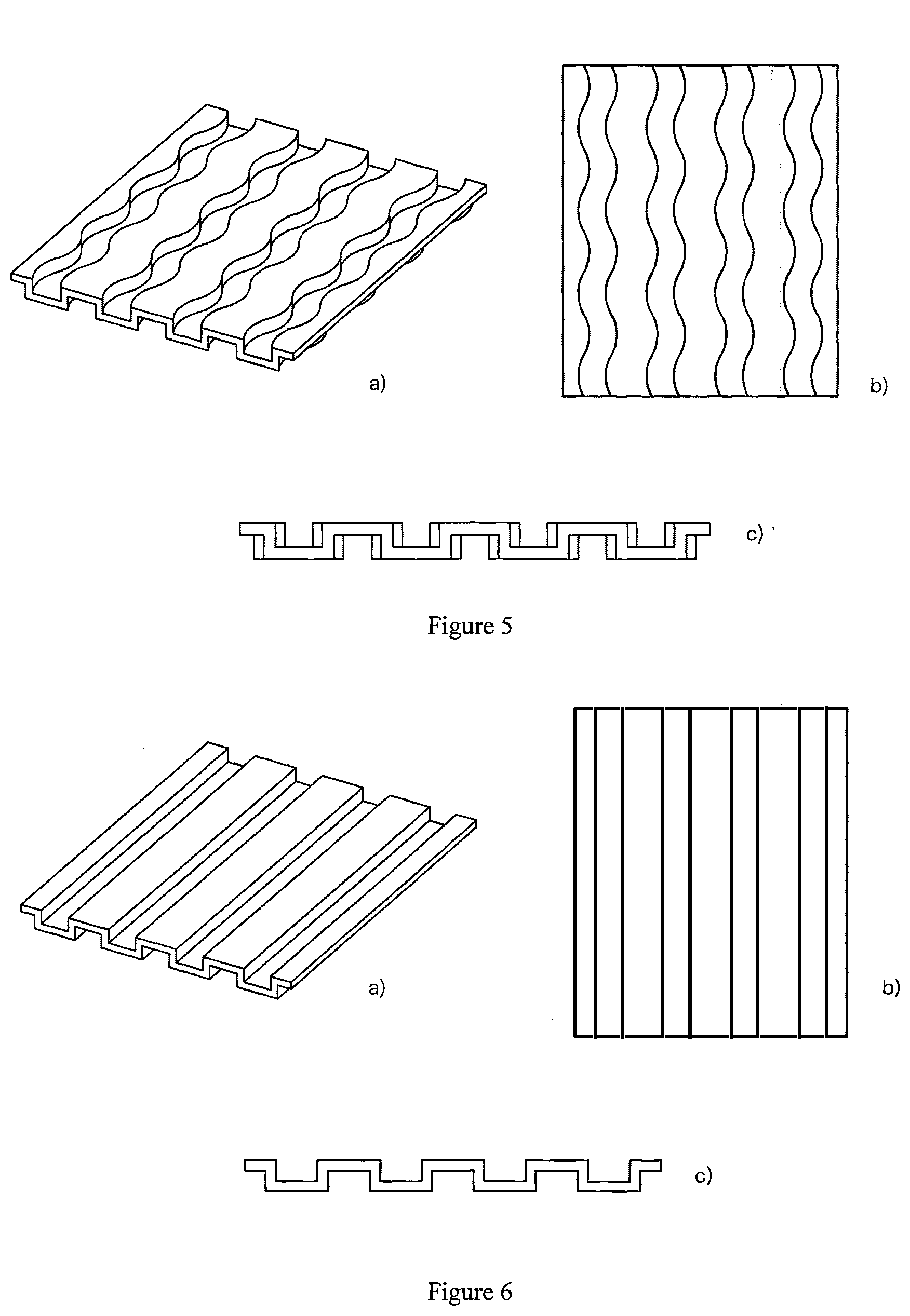
[0016] FIG. 5 shows one aspect of the high temperature heat exchanging plate and the low temperature heat exchanging plate of the comparative heat exchanger comprising the non-symmetric wavy channel from a) isometric, b) top, and c) front views.
[0017] FIG. 6 shows one aspect of the high temperature heat exchanging plate and the low temperature heat exchanging plate of the comparative heat exchanger comprising the straight channel from a) isometric, b) top, and c) front views.
[0018] FIG. 7 shows the amount of transferred heat to the flow volume of the heat exchanger according to the present invention and the heat exchanger according to the prior art.
DESCRIPTION OF THE INVENTION
[0019] The present invention relates to the heat exchanger for exchanging heat of fluids having different temperatures as described according to the following embodiments.
[0020] Any aspect used herein refers including the application to other aspects of this invention unless stated otherwise.
[0021] Technical terms or scientific terms used herein have definitions as understood by an ordinary person skilled in the art unless stated otherwise.
[0022] Any tools, equipment, methods, or chemicals mentioned herein mean tools, equipment, methods, or chemicals commonly operated or use by those person skilled in the art unless explicated that they are tools, equipment, methods, or chemicals specific only in this invention.
[0023] Use of singular noun or singular pronoun with "comprising" in claims or specification refers to "one" and also "one or more", "at least one", and "one or more than one".
[0024] The following details describe in the specification of the invention, and are not intend to limit the scope of the invention in any way. This invention discloses the heat exchanger for exchanging heat of fluids having different temperatures, comprising: at least one flat heat exchanging plate; at least one high temperature heat exchanging plate; and at least one low temperature heat exchanging plate stacked in an alternating sequence, wherein an inlet of the high temperature fluid and an outlet of the high temperature fluid are disposed in order to pass the high temperature fluids through each said high temperature heat exchanging plate, and an inlet of low temperature fluid and an outlet of low temperature fluid are disposed in order to pass a low temperature fluid through each said low temperature heat exchanging plate, wherein said high temperature heat exchanging plate and low temperature heat exchanging plate comprising a high temperature channel and a low temperature channel, wherein said channels have a length extending in a flow direction of said fluids and a side wall of each said channel has symmetric wavy curve pattern with a center line of each said channel as a symmetric axis.
[0025] FIGS. 1 and 2 show one aspect of the the heat exchanger according to the present invention. In this aspect, the heat exchanger comprising at least one flat heat exchanging plate 12; at least one high temperature heat exchanging plate 14; and at least one low temperature heat exchanging plate 16 stacked in an alternating sequence, wherein an inlet of high temperature fluid 18a and an outlet of high temperature fluid 20a are disposed in order to pass a high temperature fluid through each said high temperature heat exchanging plate 14, and an inlet of low temperature fluid 18b and an outlet of low temperature fluid 20b are disposed in order to pass the-low temperature fluid through each said low temperature heat exchanging plate 16. In each said plate, the said inlet and outlet parts assembly can be separated from the heat exchanger.
[0026] The said high temperature heat exchanging plate 14 comprising the high temperature channel 15 and said low temperature heat exchanging plate 16 comprising the low temperature channel 17, wherein said channels have a length extending the flow direction of said fluid and the side wall of each said channel has a symmetric wavy curve pattern with the center line of each said channel as a symmetric axis.
[0027] In one embodiment, the high temperature channel 15 and the low temperature channel 17 have an average width (y) in a range of 100 to 5,000 .mu.m and the curve length (x) and the curve radius (r) according to this equation:
x.ltoreq.2r,
[0028] wherein x is in a range of 100 to 100,000 .mu.m.
[0029] Preferably, said channel have the average width in the range of 100 to 3,000 .mu.m, the curve length in the range of 1,000 to 3,000 .mu.m, and the curve radius in the range of 2,000 to 5,000 .mu.m.
[0030] In one embodiment, the high temperature channel 15 and the low temperature channel 17 have the depth in the range of about 10 to 2,000 .mu.m when comparing to the plane set by the top of each high temperature heat exchanging plate 14 and each low temperature heat exchanging plate 16. Preferably, the high temperature heat exchanging plate 14 and the low temperature heat exchanging plate 16 are arranged in order to place the high temperature channel 15 and the low temperature channel 17 oriented in alternate configuration as shown in FIG. 2.
[0031] In one embodiment, the flat heat exchanging plate 12, the high temperature heat exchanging plate 14, and the low temperature heat exchanging plate 16 have a thickness in a range of about 10 to 10,000 .mu.m, preferably the thickness in the range of about 100 to 2,000 .mu.M.
[0032] In order to perform efficiently with adequate strength and dimensional stability of the heat exchanger for exchanging heat of fluids having different temperatures said heat exchanging plate may be made from carbon steel, stainless steel, aluminium, titanium, platinum, chromium, copper, or alloy of said materials, preferably made from stainless steel 316 grade (SS316).
[0033] In one embodiment, the high temperature heat exchanging plate 14 and the low temperature heat exchanging plate 16 may be formed by stamping machine technique, photo chemical machine (PCM) technique, or computer numerical control milling machine technique.
[0034] In one embodiment, the inlet of the high temperature fluid 18a and the inlet of low temperature fluid 18b are disposed in an opposite side of the heat exchanger in order to cause fluids having different temperatures to flow in the counter-current direction, wherein said fluids with different temperatures may have temperature difference at least 1.degree. C., preferably temperature difference at least 10.degree. C.
[0035] As being known by an ordinary person skilled in the art that said flat heat exchanging plate 12, the high temperature heat exchanging plate 14, and the low temperature heat exchanging plate 16 can be stacked in an alternating sequence from three plates and more, they can be stacked in higher numbers in order to provide the heat exchanger with many channels for heat exchanging of fluids with high flow rate.
[0036] In order to compare the performance of the heat exchanger according to the present invention to the heat exchanger comprising the channel according to the prior art, the heat exchanger according to this invention as the second embodiment comprising the high temperature channel 15 and the low temperature channel 17 according to the appearance in FIG. 4 and the heat exchanger comprising the high temperature channel and the low temperature channel characterized in non-symmetric wavy pattern and straight channel (according to the appearance in FIGS. 5 and 6 respectively) were build and tested with computational flow dynamics model using ANSYS Fluent Software, version 16.1 as being described below.
[0037] The Heat Exchanger According to this Invention
[0038] The Heat Exchanger 1
[0039] The thickness of each flat heat exchanging plate 12, the high temperature heat exchanging plate 14, and the low temperature heat exchanging plate 16 was 0.5 mm. The high temperature channel 15 and the low temperature channel 17 as shown in FIG. 4 had average width (y) about 2,000 .mu.m, the curve length (x) about 2,000 .mu.m, and the curve radius (r) about 3,000 .mu.m. The length of the channel was about 240 mm and the depth was about 1,000 .mu.m.
[0040] The Heat Exchanger 2
[0041] The thickness of each flat heat exchanging plate 12, the high temperature heat exchanging plate 14, and the low temperature heat exchanging plate 16 was 0.5 mm. The high temperature channel 15 and the low temperature channel 17 as shown in FIG. 4 had the average width (y) about 2,000 .mu.m, the curve length (x) about 2,000 .mu.m, and the curve radius (r) about 4,000 .mu.m. The length of the channel was about 240 mm and the depth was about 1,000 .mu.m.
[0042] The Heat Exchanger 3
[0043] The thickness of each flat heat exchanging plate 12, the high temperature heat exchanging plate 14, and the low temperature heat exchanging plate 16 was 0.5 mm. The high temperature channel 15 and the low temperature channel 17 as shown in FIG. 4 had average width (y) about 2,000 .mu.m, the curve length (x) about 3,000 .mu.m, and the curve radius (r) about 3,000 .mu.m. The length of the channel was about 240 mm and the depth was about 1,000 .mu.m.
[0044] The Heat Exchanger 4
[0045] The thickness of each flat heat exchanging plate 12, the high temperature heat exchanging plate 14, and the low temperature heat exchanging plate 16 was 0.5 mm. The high temperature channel 15 and the low temperature channel 17 as shown in FIG. 4 had the average width (y) about 2,000 .mu.m, the curve length (x) about 3,000 .mu.m, and the curve radius (r) about 4,000 .mu.m. The length of the channel was about 240 mm and the depth was about 1,000 .mu.m.
[0046] The Comparative Heat Exchanger
[0047] The Heat Exchanger a
[0048] The heat exchanger comprising the components as described in the heat exchanger 1 except that the characters of the high and the low temperature channel having a non-symmetric wavy pattern as shown in FIG. 5 was used.
[0049] The Heat Exchanger B
[0050] The heat exchanger comprising the components as described in the heat exchanger 2 except that the characters of the high and the low temperature channels having the non-symmetric pattern as shown in FIG. 5 was used.
[0051] The Heat Exchanger C
[0052] The heat exchanger comprising the components as described in the heat exchanger 3 except that the characters of the high and the low temperature channel having the non-symmetric pattern as shown in FIG. 5 was used.
[0053] The Heat Exchanger D
[0054] The heat exchanger comprising the components as described in the heat exchanger 4 except that the characters of the high and the low temperature channel having the non-symmetric pattern as shown in FIG. 5 was used.
[0055] The Heat Exchanger E
[0056] The heat exchanger comprising the components as described in the heat exchanger 1 except that the characters of the high and the low temperature channel having the straight path with about 2,000 .mu.m width as shown in FIG. 6 was used.
[0057] The heat exchanger comprising different characters of the channel as described above was tested for heat exchanging performance using ANSYS Fluent software version 16.1 with the following parameters. Fluids used in the model were water at different temperatures, wherein the high temperature fluid was about 90.degree. C. and the low temperature fluid was about 10.degree. C. The said fluids flowed in the counter-current direction with flow velocity in each path about 0.582 g/sec. The results were shown in table 1 and FIG. 7.
[0058] Table 1 shows temperature of the high temperature fluids outlet and the temperature of the low temperature fluids outlet from the outlet of the heat exchanger comprising different characters of the high temperature channel and the low temperature channel.
TABLE-US-00001 Temperature of the high Temperature of the low Heat temperature fluids outlet temperature fluids outlet exchanger (.degree. C.) (.degree. C.) A 53.0 47.0 B 64.7 35.3 C 52.4 47.6 D 62.4 37.6 E 66.5 33.5 1 51.9 48.1 2 55.4 44.6 3 48.2 51.3 4 51.0 48.8
[0059] The performance of the heat exchanger can be considered from the temperature of the high temperature fluid outlets and the temperature of the low temperature fluid outlet as shown in table 1 and the heat transferred per fluid volume as shown in FIG. 7.
[0060] From FIG. 7, when comparing the heat exchanger according to the invention 1 to the comparative heat exchanger A, E, the heat exchanger according to the invention 2 to the comparative heat exchanger B, E, the heat exchanger according to the invention 3 to the comparative heat exchanger C, E, and the heat exchanger according to the invention 4 to the comparative heat exchanger D, E, it was found that the heat exchanger according to the present invention gave higher heat transferred per fluid volume, wherein the heat exchanger according to the invention 3 whose channel had symmetric wavy pattern with average width about 2,000 .mu.m, the curve length about 3,000 .mu.m, and the curve radius about 3,000 .mu.m provided highest performance.
[0061] Moreover, in order to compare the strength of the heat exchanger according to present invention and the heat exchanger comprising the channel according to the prior art, the heat exchanger comprising different characters of the channel as described above was tested using ANSYS Fluent software version 16.1. The parameters were set as the following. The heat exchanging plates were made from 316 grade stainless steel (SS316). The pressure of the high temperature fluid was about 1.5 MPa. The pressure of the low temperature fluid was about 0.5 MPa. The heat exchanging plates were fixed at the edges of the heat exchanging plates. Results were shown in table 2, wherein volumetric percentage of the heat exchanging plates in each stage of the equivalent stress were calculated from the following equation:
Volume of the heat exchanging plate with equivalent stress in that stage Volume of total heat exchanging plate .times. 100 ##EQU00001##
[0062] Table 2 shows the comparison of the strength of the heat exchanger comprising different characters of the temperature channel and the low temperature channel.
TABLE-US-00002 Volumetric percentage of the heat exchanging Maximum plates in equivalent stress in each stage equivalent Heat 0-3 3-6 6-9 stress exchanger MPa MPa MPa (MPa) A 87.1 12.2 0.7 7.69 B 86.7 12.3 1.0 7.56 C 90.7 9.1 0.2 6.69 D 88.7 10.8 0.5 7.19 E 86.1 12.8 1.1 7.16 1 87.2 12.0 0.8 7.41 2 86.8 12.3 1.0 7.36 3 90.4 9.4 0.2 6.66 4 88.9 10.7 0.4 7.11
[0063] Table 2 shows the comparison of the strength of the heat exchanger according to present invention to the heat exchanger according to the prior art, which could be considered from the maximum equivalent stress and volumetric percentage of the heat exchanging plates in each stage of the equivalent stress happened to the heat exchanging plates of the heat exchanger during heat transferring of the fluids with different temperatures. From the table, the channel of the heat exchanger according to the invention 3 had the symmetric wavy pattern with the average width about 2,000 .mu.m, the curve length about 3 mm, and the curve radius about 3 mm, wherein the highest strength was considered from the lowest maximum equivalent stress, the high volumetric percentage of the heat exchanging plate in low equivalent stress stage (0-3 MPa), and the high volumetric percentage of the heat exchanging plate in high equivalent stress stage (6-9 MPa). Moreover, the maximum equivalent stress of the heat exchanger according to this present invention had a lower tensile yield strength than the 316 grade stainless steel (about 207 MPa), used as sample material in strength test. This showed that said heat exchanging plate of the heat exchanger did not permanently deformed when operated at the above conditions.
[0064] From the above results, it is confirmed that the heat exchanger according to present invention has high performance in heat transferring of the fluids with different temperatures, has high strength, and can be used for the heat exchanging of the fluids with highly different pressures as being said in the objectives of this invention.
BEST MODE OF THE INVENTION
[0065] Best mode of the invention is as provided in the description of the invention.
* * * * *
uspto.report is an independent third-party trademark research tool that is not affiliated, endorsed, or sponsored by the United States Patent and Trademark Office (USPTO) or any other governmental organization. The information provided by uspto.report is based on publicly available data at the time of writing and is intended for informational purposes only.
While we strive to provide accurate and up-to-date information, we do not guarantee the accuracy, completeness, reliability, or suitability of the information displayed on this site. The use of this site is at your own risk. Any reliance you place on such information is therefore strictly at your own risk.
All official trademark data, including owner information, should be verified by visiting the official USPTO website at www.uspto.gov. This site is not intended to replace professional legal advice and should not be used as a substitute for consulting with a legal professional who is knowledgeable about trademark law.