Air Heater
MARINO; Ryan J. ; et al.
U.S. patent application number 16/401282 was filed with the patent office on 2019-11-07 for air heater. The applicant listed for this patent is TTI (MACAO COMMERCIAL OFFSHORE) LIMITED. Invention is credited to Matthew T. AARON, Wen Jie CHAI, Ryan J. MARINO, Brent M. WILLEY, Guo Hong YIN.
| Application Number | 20190338950 16/401282 |
| Document ID | / |
| Family ID | 66397158 |
| Filed Date | 2019-11-07 |
| United States Patent Application | 20190338950 |
| Kind Code | A1 |
| MARINO; Ryan J. ; et al. | November 7, 2019 |
AIR HEATER
Abstract
A liquid fuel air heater comprises a housing defining a motor housing portion and a grip portion extending from the motor housing portion. An electric motor is positioned in the motor housing portion. A combustion chamber is at least partially positioned within the motor housing portion. A fan is driven by the motor when activated for generating an axial airflow through the combustion chamber. A battery pack containing a plurality of battery cells connected to each other in a series or parallel arrangement is removably coupled to the grip portion of the housing for supplying power to the motor.
| Inventors: | MARINO; Ryan J.; (Greenville, SC) ; WILLEY; Brent M.; (Anderson, SC) ; YIN; Guo Hong; (Dongguan City, CN) ; CHAI; Wen Jie; (Dongguan City, CN) ; AARON; Matthew T.; (Greenville, SC) | ||||||||||
| Applicant: |
|
||||||||||
|---|---|---|---|---|---|---|---|---|---|---|---|
| Family ID: | 66397158 | ||||||||||
| Appl. No.: | 16/401282 | ||||||||||
| Filed: | May 2, 2019 |
| Current U.S. Class: | 1/1 |
| Current CPC Class: | F23N 2225/16 20200101; F23N 2221/04 20200101; F24H 3/0423 20130101; F23N 2237/00 20200101; F23N 5/10 20130101; F23L 5/02 20130101; F24H 3/0488 20130101; F23N 2235/14 20200101; F23D 14/465 20130101; F23D 14/38 20130101; F23D 14/36 20130101; F23N 3/087 20130101; F23N 2227/10 20200101; F23N 2241/02 20200101; F23D 14/28 20130101 |
| International Class: | F23N 5/10 20060101 F23N005/10; F23N 3/08 20060101 F23N003/08 |
Foreign Application Data
| Date | Code | Application Number |
|---|---|---|
| May 3, 2018 | CN | 201810414529.6 |
Claims
1. A liquid fuel air heater comprising: a housing defining a motor housing portion and a grip portion extending from the motor housing portion; an electric motor positioned in the motor housing portion; a combustion chamber at least partially positioned within the motor housing portion; a fan driven by the motor when activated for generating an axial airflow through the combustion chamber; and a battery pack containing a plurality of battery cells connected to each other in a series or parallel arrangement, the battery pack being removably coupled to the grip portion of the housing for supplying power to the motor.
2. The liquid fuel air heater of claim 1, further comprising a liquid fuel container for providing liquid fuel to the combustion chamber.
3. The liquid fuel air heater of claim 2, further comprising a control valve to alternatively permit or prevent the flow of liquid fuel from the liquid fuel container to the combustion chamber.
4. The liquid fuel air heater of claim 3, wherein the control valve is a solenoid actuated valve.
5. The liquid fuel air heater of claim 3, further comprising an ignitor configured to ignite liquid fuel in the combustion chamber.
6. The liquid fuel air heater of claim 5, further comprising an actuator moveable between a first position in which the motor is off and the control valve is closed and a second position, wherein the actuator biased to the first position, and wherein when the actuator is in the second position for a predetermined period of time, the control valve is opened, the ignitor creates sparks to ignite liquid fuel in the combustion chamber, and the motor is activated.
7. The liquid fuel air heater of claim 6, wherein after the control valve is opened, if a temperature of the combustion chamber is below a threshold temperature for a second predetermined period of time, the control valve is closed.
8. The liquid fuel air heater of claim 3, wherein after the control valve is opened, if a temperature of the combustion chamber is below a threshold temperature for a predetermined period of time, the control valve is closed.
9. The liquid fuel air heater of claim 8, wherein after the control valve is opened, if a temperature of the combustion chamber is greater than or equal to the threshold temperature for a predetermined period of time, the control valve is kept open.
10. The liquid fuel air heater of claim 9, further comprising a thermocouple configured to produce a voltage that is proportional to the temperature of the combustion chamber and provided as an input to a controller, wherein after the control valve is opened if the temperature of the combustion chamber is greater than or equal to the threshold temperature for the predetermined period of time, the controller keeps the control valve open in response to receiving the input.
11. The liquid fuel air heater of claim 3, further comprising a heating blanket in thermal contact with and at least partially surrounding the liquid fuel container, wherein the heating blanket, when activated, increases a temperature of the liquid fuel container.
12. The liquid fuel air heater of claim 11, wherein the heating blanket is activated when the temperature of the liquid fuel container falls below a threshold temperature.
13. A liquid fuel air heater comprising: a housing defining a motor housing portion; an electric motor positioned in the motor housing portion; a combustion chamber at least partially positioned within the motor housing portion; a fan driven by the motor when activated for generating an axial airflow through the combustion chamber; a liquid fuel container at least partially positioned in the housing for providing liquid fuel to the combustion chamber; and a heating blanket in thermal contact with and at least partially surrounding the liquid fuel container, wherein the heating blanket, when activated, increases the temperature of the liquid fuel container.
14. The liquid fuel air heater of claim 13, wherein the heating blanket is activated when a temperature of the liquid fuel container falls below a threshold temperature.
15. The liquid fuel air heater of claim 13, wherein the housing defines a grip portion extending from the motor housing portion.
16. The liquid fuel air heater of claim 15, further comprising a battery pack containing a plurality of battery cells connected to each other in a series or parallel arrangement, wherein the battery pack is removably coupled to the grip portion of the housing for supplying power to the motor.
17. The liquid fuel air heater of claim 13, further comprising an ignitor configured to ignite liquid fuel in the combustion chamber and a control valve to alternatively permit or prevent the flow of liquid fuel from the liquid fuel container to the combustion chamber.
18. The liquid fuel air heater of claim 17, further comprising an actuator moveable between a first position in which the motor is off and the control valve is closed and a second position, the actuator biased to the first position, and wherein when the actuator is in the second position for a first predetermined period of time, the control valve is opened, the ignitor creates sparks to ignite liquid fuel in the combustion chamber, and the motor is activated.
19. The liquid fuel air heater of claim 18, wherein after the control valve is opened, if a temperature of the combustion chamber is below a threshold temperature for a second predetermined period of time, the control valve is closed, and if the temperature of the combustion chamber is greater than or equal to the threshold temperature for the second predetermined period of time, the control valve is kept open.
20. The liquid fuel air heater of claim 19, further comprising a thermocouple configured to produce a voltage that is proportional to the temperature of the combustion chamber and provided as an input to a controller, wherein after the control valve is opened if the temperature of the combustion chamber is greater than or equal to the threshold temperature for the predetermined period of time, the controller keeps the control valve open in response to receiving the input.
21. The liquid fuel air heater of claim 17, wherein after the control valve is opened, if a temperature of the combustion chamber is below a threshold temperature for a predetermined period of time, the control valve is closed, and if the temperature of the combustion chamber is greater than or equal to the threshold temperature for the predetermined period of time, the control valve is kept open.
22-28. (canceled)
Description
FIELD OF THE INVENTION
[0001] The present invention relates to air heaters, and more particularly to liquid fuel air heaters.
BACKGROUND OF THE INVENTION
[0002] Air heaters may use liquid fuel for combustion to create a heated airflow for discharge into the environment. The liquid fuel may be provided from a liquid fuel container on board the air heater.
SUMMARY OF THE INVENTION
[0003] The present invention provides, in one aspect, a liquid fuel air heater comprising a housing defining a motor housing portion and a grip portion extending from the motor housing portion, an electric motor positioned in the motor housing portion, a combustion chamber at least partially positioned within the motor housing portion, a fan driven by the motor when activated for generating an axial airflow through the combustion chamber and a battery pack containing a plurality of battery cells connected to each other in a series or parallel arrangement, the battery pack being removably coupled to the grip portion of the housing for supplying power to the motor.
[0004] The present invention provides, in another aspect, a liquid fuel air heater comprising a housing defining a motor housing portion, an electric motor positioned in the motor housing portion, a combustion chamber at least partially positioned within the motor housing portion, a fan driven by the motor when activated for generating an axial airflow through the combustion chamber, a liquid fuel container at least partially positioned in the housing for providing liquid fuel to the combustion chamber, and a heating blanket in thermal contact with and at least partially surrounding the liquid fuel container. The heating blanket, when activated, increases the temperature of the liquid fuel container.
[0005] The present invention provides, in yet another aspect, a method of operating a liquid fuel air heater comprising moving an actuator from a first position to a second position a first instance, initiating a first timer in response to the actuator reaching the second position, following expiration of the first timer, detecting whether the actuator is in the first position or the second position, following detection of the actuator in the second position, opening a control valve to direct liquid fuel from an onboard liquid fuel container into a combustion chamber, directing an electrical current to an ignitor in the combustion chamber to ignite the fuel in the combustion chamber, and activating a motor to drive a fan for generating an axial airflow through the combustion chamber, which is heated by the combusting fuel and discharged from the combustion chamber.
[0006] Other features and aspects of the invention will become apparent by consideration of the following detailed description and accompanying drawings.
BRIEF DESCRIPTION OF THE DRAWINGS
[0007] FIG. 1 is a perspective view of a liquid fuel air heater.
[0008] FIG. 2 is a plan view of the liquid fuel air heater of FIG, 1 with portions removed.
[0009] FIG. 3 is a schematic of the liquid fuel air heater of FIG. 1.
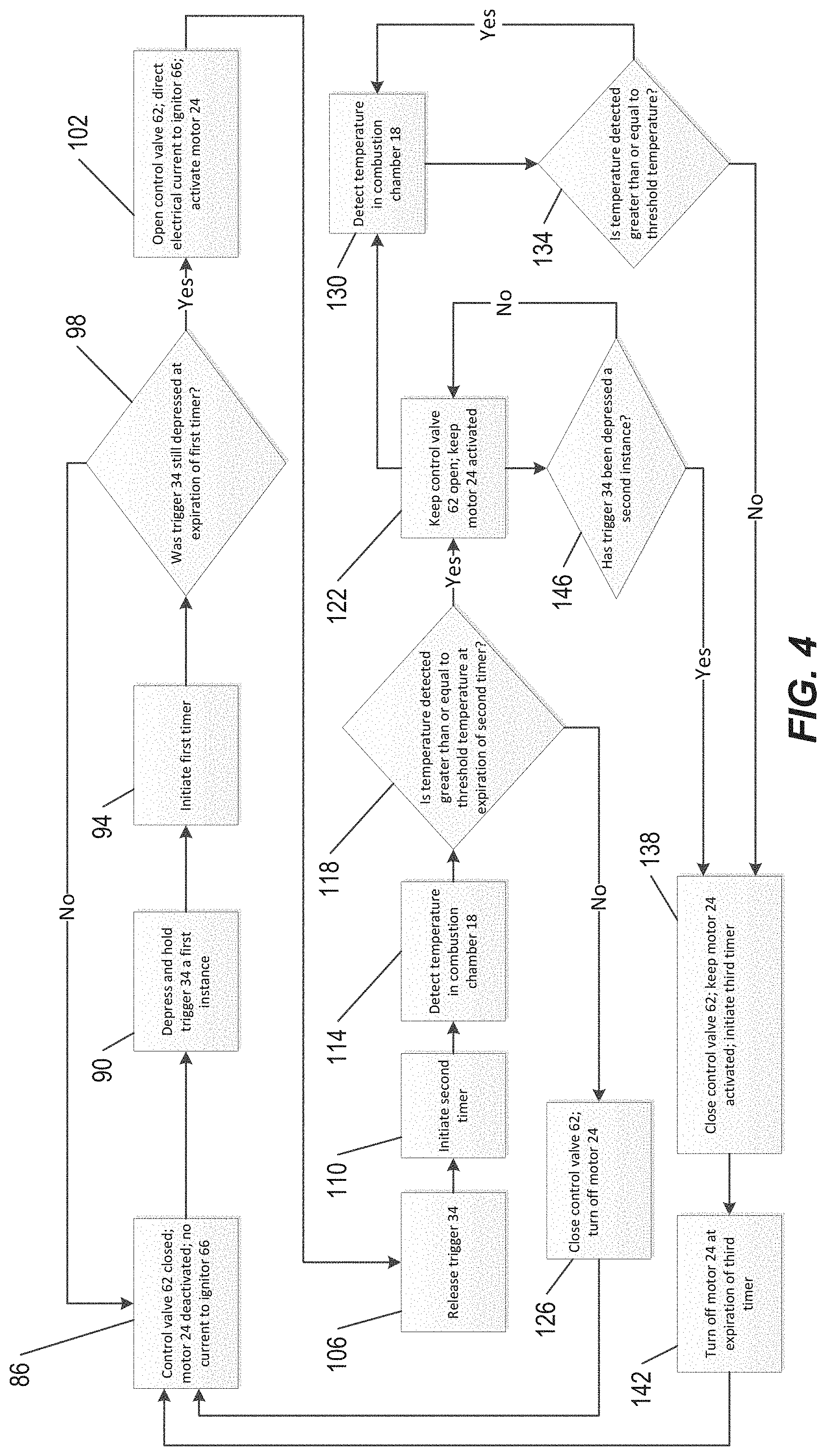
[0010] FIG. 4 is a flowchart illustrating a method of operating the liquid fuel air heater of FIG. 1.
[0011] Before any embodiments of the invention are explained in detail, it is to be understood that the invention is not limited in its application to the details of construction and the arrangement of components set forth in the following description or illustrated in the following drawings. The invention is capable of other embodiments and of being practiced or of being carried out in various ways. Also, it is to be understood that the phraseology and terminology used herein is for the purpose of description and should not be regarded as limiting.
DETAILED DESCRIPTION
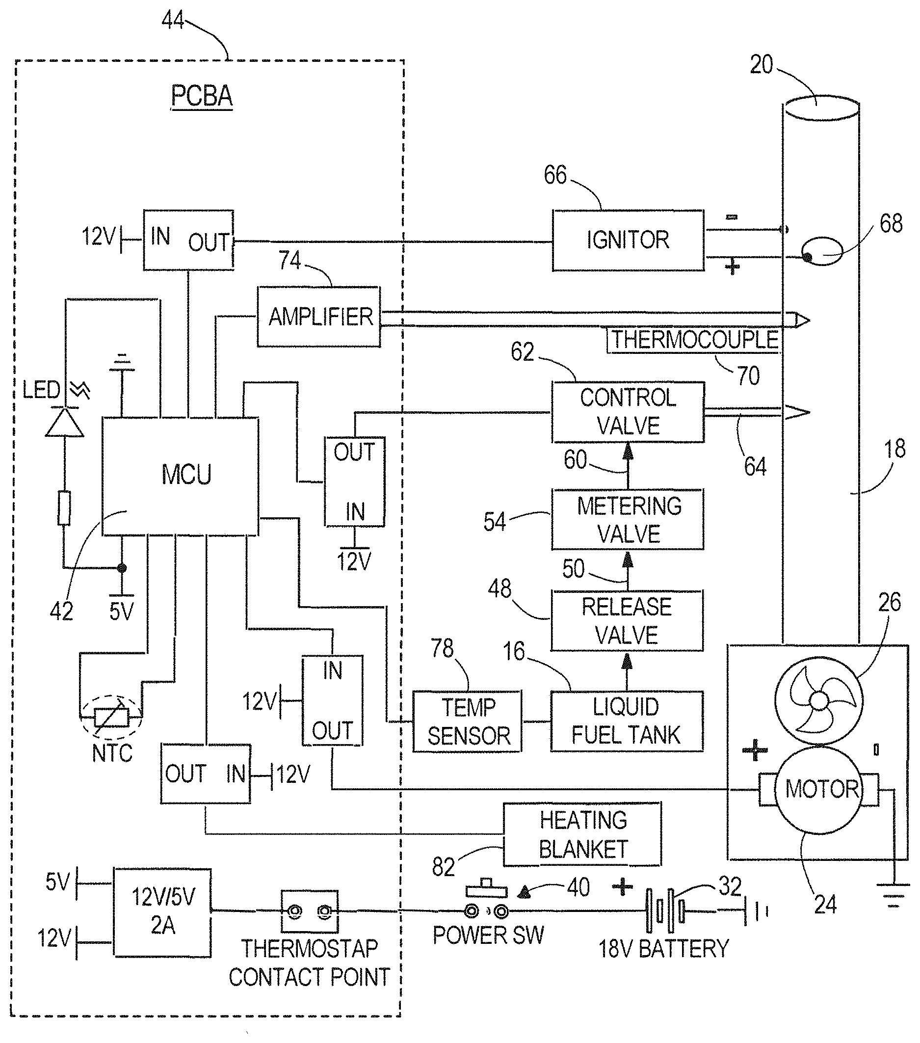
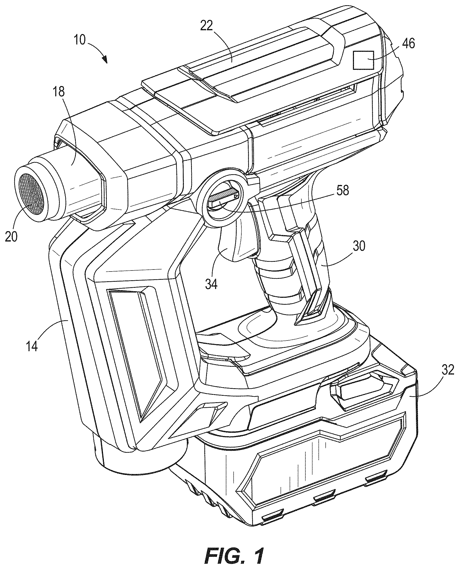
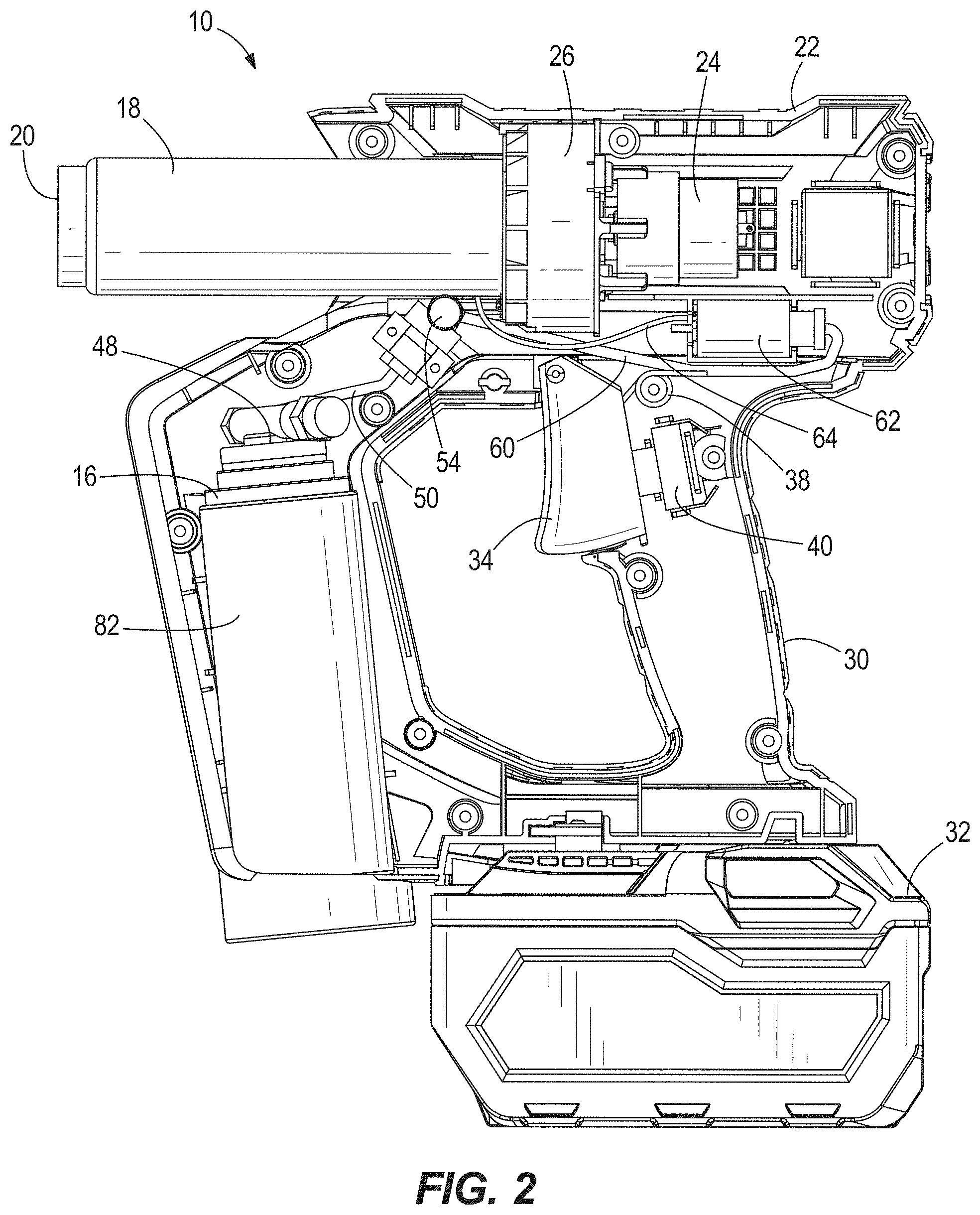
[0012] FIGS. 1-3 illustrate an air heater 10 according to an embodiment of the invention. The air heater 10 includes a housing 14, a liquid fuel container 16, a combustion chamber 18, and a heat outlet 20 for directing a heated airflow towards a target. The housing 14 defines a motor housing portion 22, which houses the combustion chamber 18 and a motor 24 to drive a fan 26 that is arranged on an opposite side of the combustion chamber 18 as the heat outlet 20, and a grip portion 30 extending from the motor housing portion 22 that is graspable by an operator while the air heater 10 is in use. In the illustrated embodiment, the liquid fuel container 16 contains a reservoir of liquid butane, but in other embodiments, the liquid fuel container may contain other combustible liquids.
[0013] A battery pack 32 is removably coupled to the grip portion 30 to provide power to the motor 24 and the other components of the air heater 10 requiring electrical power. In the illustrated embodiment, the battery pack 32 is an 18 V battery pack but may alternatively include any of a number of different nominal voltages (e.g., 12 V, 24 V, etc.), and may be configured having any of a number of different chemistries (e.g., lithium-ion, nickel-cadmium, etc.). The battery pack 32 contains a plurality of battery cells connected to each other in a series or parallel arrangement.
[0014] In the illustrated embodiment, the grip portion 30 is a pistol-grip handle but in other embodiments the grip portion 30 can have other shapes and orientations. The air heater 10 includes an actuator, such as a trigger 34, located in the grip portion 30 and biased to a first, extended, position by a torsion spring 38 (FIG. 2). When the trigger 34 is depressed to a second, depressed, position against the biasing force of the torsion spring 38, the trigger 34 is configured to actuate a switch 40, which provides an input to a controller governing operation of the air heater 10. In the illustrated embodiment of the air heater 10 as shown in FIG. 3, the controller is configured as a microcontroller unit ("MCU") 42 provided on a printed circuit board assembly 44. The air heater 10 also includes an 46 to provide indications to the operator, via different lighted colors or blinking patterns, coinciding with different stages of operation, as explained in further detail below.
[0015] With reference to FIG. 2, the liquid fuel container 16 has a release valve 48, which is in fluid communication with an inlet of a metering valve 54 via a conduit 50. The metering valve 54 is adjustable using an adjustment knob 58 (FIG. 1) to control the flow rate of liquid fuel exiting the metering valve 54. In the illustrated embodiment, the metering valve 54 is a needle valve but in other embodiments, other valve types may be used. As such, by adjusting the flow rate of liquid fuel that is ultimately delivered to the combustion chamber 18, the temperature of the heated airflow discharged from the outlet 20 can be adjusted.
[0016] With continued reference to FIG. 2, the air heater 10 also includes a control valve 62 having an inlet in fluid communication with an outlet of the metering valve 54 via a conduit 60. An outlet of the control valve 62 is in fluid communication with the combustion chamber 18 via a conduit 64. In the illustrated embodiment of the air heater 10, the control valve 62 is a solenoid-actuated valve 62 that is electrically connected with the MCU 42. The MCU 42, in turn, is capable of switching the valve 62 between an open state in which the flow of liquid fuel from the liquid fuel container 16 to the combustion chamber 18 is permitted, and a closed state, in which the liquid fuel is prevented from being discharged into the combustion chamber 18. The valve 62 is biased into the closed state, such that without an electrical input from the MCU 42, the valve 62 will remain closed and liquid fuel from the container 16 is prevented from being discharged into the combustion chamber 18,
[0017] With reference to FIG. 3, the air heater 10 includes an ignitor 66 located at least partially within the combustion chamber 18 and that is electrically connected with the MCU 42. The combustion chamber 18 includes an orifice 68 in which the liquid fuel from the conduit 64 enters to be ignited by the igniter 66. A thermocouple 70 is located proximate or within the combustion chamber 18 and is also electrically connected with the MCU 42 via an amplifier 74.
[0018] As shown in FIG. 3, a temperature sensor 78 is arranged proximate the liquid fuel container 16 to monitor the temperature of the liquid fuel container 16. A heating blanket 82 is wrapped around and is in thermal contact with the liquid fuel container 16 (see also FIG. 2). The heating blanket 82 is also electrically connected with the MCU 42. As discussed in further detail below, when the heating blanket 82 is activated by the MCU 42, it increases the temperature of the liquid fuel container 16, and therefore the pressure of the compressed gas inside the container 16 expelling the liquid fuel therefrom.
[0019] FIG. 4 is a flowchart illustrating a method of operating the air heater 10. In operation, as shown at step 86, prior to the user depressing the trigger 34 and actuating the switch 40, the control valve 62 is initially in its closed state blocking the flow of liquid fuel from the container 16 to the combustion chamber 18. At step 86, the motor 24 is also deactivated, such that the fan 26 is not running, and no current is flowing to the ignitor 66. However, as long as the motor 24 is being powered by the battery 32, the LED 46 indicates to the operator that the air heater 10 is "ready for use." At step 90, upon a first instance of an operator depressing the trigger 34 against the bias of the torsion spring 38, the switch 40 is closed, thereby providing an electrical signal (i.e., a voltage input) to the MCU 42. Upon detecting this trigger actuation signal, the MCU 42 initiates a first timer, which will run for a first predetermined period of time, as shown at step 94. In response to the trigger actuation signal, the LED 46 indicates to the operator that the air heater 10 is "warming up."
[0020] Then, at step 98, the MCU checks to determine whether the trigger 34 is still depressed and switch 40 is still closed upon expiration of the first timer. If the trigger 34 is not still depressed, the control valve 62 remains closed, the motor 24 remains deactivated, and no current flows to ignitor 66. If however, the trigger 34 is still depressed, the MCU 42 energizes the control valve 62 to direct liquid fuel into the combustion chamber 18 and (for a limited time) directs an electrical current to the ignitor 66, creating repeated sparks to ignite the discharged liquid fuel at the orifice 68 in the combustion chamber 18, as shown at step 102. This ensures that a brief accidental or inadvertent depression of the trigger 34 will not initiate operation of the air heater 10.
[0021] In some embodiments, the liquid fuel is preheated prior to combustion at the orifice 68. Specifically, prior to entering the orifice 68, the liquid fuel is heated by the flame in the combustion chamber 18 to a threshold temperature at which the liquid fuel is vaporized into a gaseous fuel state. The gaseous fuel then enters the orifice 68 for combustion by the ignitor 66. Thus, in these embodiments, liquid fuel is prevented from entering the orifice 68. Rather the fuel only enters the orifice 68 in a gaseous state.
[0022] Concurrently with or shortly after the MCU 42 directs an electrical current through the ignitor 66, the MCU 42 also activates the motor 24 to rotate the fan 26 as shown at step 102. The fan 26 generates an axial airflow through the combustion chamber 18, which is heated by the combusting liquid fuel. The heated airflow is then discharged from the heat outlet 20. In response to the opening of control valve 62, the current to ignitor 66, and activation of motor 24 to drive fan 26, the LED 46 indicates to the operator that the air heater 10 is "on", thus signaling to the operator that the trigger 34 may be released. Then, as shown at step 106, the operator may release trigger 34 while the control valve 62 remains open and motor 24 continues to drive fan 26. Thus, an operator may release the trigger 34 while liquid fuel continues to flow to the combustion chamber 18 to continue the heating operation, rather than needing to continually hold the trigger 34 depressed.
[0023] With continued reference to FIG. 4, during operation of the air heater 10, the thermocouple 70 produces a voltage that is proportional to the temperature in the combustion chamber 18 using the thermoelectric or "Seebeck" effect. The amplifier 74 amplifies the voltage output by the thermocouple 70, and the amplified voltage is provided to the MCU 42 as a voltage input proportional to the temperature in the combustion chamber 18. Because the thermocouple 70 is at an ambient temperature prior to operation of the air heater 10, after expiration of the first timer, the MCU 42 initiates a second timer, as shown at step 110. The second timer will run for a second predetermined period of time while the control valve 62 will remain energized (and therefore in its open state) and the motor 24 will remain activated to rotate the fan 26, regardless of the temperature detected by the thermocouple 70, and regardless of whether the trigger 34 remains held in its depressed position or is released. As shown at step 114, the thermocouple continues to produce voltage proportional to the temperature in the combustion chamber 18, thereby "detecting" the temperature of the combustion chamber 18.
[0024] As shown at step 118, upon expiration of the second timer, the MCU determines whether the temperature in the combustion chamber 18 is greater than or equal to a threshold temperature as detected by the thermocouple 70. If the temperature in the combustion chamber 18 is greater than or equal to the threshold temperature the MCU 42 will maintain the control valve 62 in its open state and continue to drive the motor 24 and fan 26, as shown at step 122.
[0025] If the temperature in the combustion chamber 18 has not, upon expiration of the second timer, reached the threshold temperature, the MCU 42 will de-energize the control valve 62 (thereby switching it from the open state to the closed state) and deactivate the motor 24, as shown at step 126. Thus, if the ignitor 66 fails to ignite the liquid fuel after the trigger 34 is depressed for the first time, the control valve 62 will close and discontinue the flow of liquid fuel to the combustion chamber 18. In response to the temperature not reaching the threshold temperature upon expiration of the second timer, the LED 46 indicates to the operator that ignition failed, thus signaling to the operator that the process for starting the air heater 10 must be re-initiated at step 90.
[0026] If the control valve 62 is kept open and the motor 24 remains activated at step 122, the temperature of the combustion chamber 18 continues to be detected at step 130 via the thermocouple 70 and amplifier 74 as described above. As shown at step 134, the MCU 42 continuously determines whether the temperature of the combustion chamber 18 detected at step 130 is greater than or equal to the threshold temperature. If the temperature in the combustion chamber 18 is greater than or equal to the threshold temperature, the process run by the MCU 42 simply returns to step 130 and continues cycling between steps 130 and 134 for as long as the temperature of the combustion chamber 18 is equal to or above the threshold temperature. If, however, the temperature in the combustion chamber 18 ever drops below the threshold temperature as determined at step 134 after a period of continuous operation of the air heater 10 (coinciding with a flame-out), the MCU 42 will de-energize the control valve 62 (thereby switching it from the open state to the closed state) and initiate a third timer while the motor 24 continues to drive the fan 26, as shown at step 138. In response to a flame out, the LED 46 indicates to the operator that a flame out has occurred.
[0027] While the third timer is running, the motor 24 continues to drive the fan 26 during a "cool down" period, during which the LED indicates to the operator that the air heater 10 is going through a "cool down." Upon expiration of third timer the motor 24 is deactivated and thus the fan 26 stops running, as shown at step 142. In some embodiments, the third timer is 30 seconds but in other embodiments, the third timer is longer or shorter than 30 seconds.
[0028] Alternatively, as shown at step 146, the operator may simply depress the trigger 34 a second instance to actuate the switch 40 again, prompting the MCU 42 to close the control valve 62 and initiate the third timer while the motor 24 continues to drive the fan 26 for the "cool down" process, as shown at step 138.
[0029] During operation, as the liquid fuel in the liquid fuel container 16 is used up, the tank gets colder and the pressure in the liquid fuel container 16 drops, affecting (i.e., reducing) the flow rate of the liquid fuel discharged into the combustion chamber 18. Thus, during operation of the air heater 10, the temperature sensor 78 continuously monitors the temperature of the liquid fuel container 16 (FIG. 3). If the temperature of the liquid fuel container 16 drops below a threshold temperature, the temperature sensor 78 provides an electrical signal (e.g., a voltage input) to the MCU 42, which in turn activates the heating blanket 82 to raise and/or maintain the liquid fuel container 16 at a predetermined temperature, such as 35 degrees Celsius. Thus, the heating blanket 82 prevents the temperature of the liquid fuel container 16 from falling so low that the pressure in the liquid fuel container 16 is insufficient to provide a constant flow rate of liquid fuel from the container 16.
[0030] Various features of the invention are set forth in the following claims.
* * * * *
D00000
D00001
D00002
D00003
D00004
XML
uspto.report is an independent third-party trademark research tool that is not affiliated, endorsed, or sponsored by the United States Patent and Trademark Office (USPTO) or any other governmental organization. The information provided by uspto.report is based on publicly available data at the time of writing and is intended for informational purposes only.
While we strive to provide accurate and up-to-date information, we do not guarantee the accuracy, completeness, reliability, or suitability of the information displayed on this site. The use of this site is at your own risk. Any reliance you place on such information is therefore strictly at your own risk.
All official trademark data, including owner information, should be verified by visiting the official USPTO website at www.uspto.gov. This site is not intended to replace professional legal advice and should not be used as a substitute for consulting with a legal professional who is knowledgeable about trademark law.