Variable Displacement Pump
Bennett, SR.; Andy ; et al.
U.S. patent application number 15/968855 was filed with the patent office on 2019-11-07 for variable displacement pump. The applicant listed for this patent is GM GLOBAL TECHNOLOGY OPERATIONS LLC. Invention is credited to Andy Bennett, SR., Sean M. McGowan, Bryan K. Pryor, David R. Staley.
| Application Number | 20190338771 15/968855 |
| Document ID | / |
| Family ID | 68276585 |
| Filed Date | 2019-11-07 |


| United States Patent Application | 20190338771 |
| Kind Code | A1 |
| Bennett, SR.; Andy ; et al. | November 7, 2019 |
VARIABLE DISPLACEMENT PUMP
Abstract
A variable displacement vane pump includes a housing, an expandable vane control ring, a rotor, a plurality of vanes, slider ring, and biasing means. The expandable vane control ring defines a gap. The plurality of vanes may be slidably disposed in the rotor. The slider ring is pivotally affixed to the housing via a pivot. The slider ring may form a plurality of pumping chambers with the expandable vane control ring, the rotor and the vanes. The distal end of each vane in the plurality of vanes is configured to abut and slide along an inner surface of the slider ring while the rotor rotates and the expandable vane control ring is configured to temporarily contract when intermittent friction is experienced between the inner surface and any vane in the plurality of vanes--so that the plurality of vanes continuously slide along an inner surface of the slider ring.
| Inventors: | Bennett, SR.; Andy; (Rochester Hills, MI) ; McGowan; Sean M.; (Northville, MI) ; Pryor; Bryan K.; (Waterford, MI) ; Staley; David R.; (Flushing, MI) | ||||||||||
| Applicant: |
|
||||||||||
|---|---|---|---|---|---|---|---|---|---|---|---|
| Family ID: | 68276585 | ||||||||||
| Appl. No.: | 15/968855 | ||||||||||
| Filed: | May 2, 2018 |
| Current U.S. Class: | 1/1 |
| Current CPC Class: | F04C 14/226 20130101; F04C 2210/206 20130101; F01M 1/02 20130101; F04C 2/3442 20130101; F01M 1/16 20130101; F04C 14/22 20130101; F01M 2001/0246 20130101; F01C 21/0836 20130101; F01M 2001/0238 20130101 |
| International Class: | F04C 2/344 20060101 F04C002/344; F01M 1/02 20060101 F01M001/02; F01M 1/16 20060101 F01M001/16; F04C 14/22 20060101 F04C014/22 |
Claims
1. A variable displacement vane pump comprising: a housing defining inlet and discharge ports; an expandable vane control ring defining a gap and an expandable diameter; a rotor driven by the drive shaft and coaxially aligned a drive shaft; a plurality of vanes slidably disposed in the rotor, the plurality of vanes and the rotor being disposed within the expandable vane control ring; a slider ring pivotally affixed to the housing via a pivot, the slider ring defining a displacement control region with a first portion of the housing, the slider ring 16 cooperating with the expandable vane control ring, the rotor, and the plurality of vanes to form a plurality of pumping chambers that are successively connected to the inlet and discharge ports; a biasing means acting on the slider ring and urging the slider ring in a first direction via a first force; and a control unit configured to generate a varying input working fluid pressure via an input working fluid flow to the displacement control region thereby generating a second force on the slider ring about the pivot means in a second direction opposite to the first direction, the second force configured to vary relative to the first force so as vary each pumping chamber and vary the expandable diameter of the expandable vane control ring by pivoting the slider ring while the rotor rotates via the drive shaft.
2. The variable displacement vane pump as defined in claim 1 wherein the gap of the expandable vane control ring decreases when the expandable diameter of the expandable vane control ring decreases.
3. The variable displacement vane pump as defined in claim 2 wherein the gap of the expandable vane control ring increases when the expandable diameter of the expandable vane control ring increases.
4. The variable displacement vane pump as defined in claim 3 wherein the expandable vane control ring defines a plurality of tabs configured to prevent a vane in the plurality of vanes from engaging with the gap.
5. The variable displacement vane pump as defined in claim 4 wherein a tab is defined at each end of the expandable vane control ring.
6. The variable displacement vane pump as defined in claim 5 wherein an aperture is defined in each tab disposed at each end of the expandable vane control ring.
7. The variable displacement vane pump as defined in claim 6 wherein the aperture is configured to engage with an assembly tool aid.
8. The variable displacement vane pump as defined in claim 3 wherein an aperture is defined proximate to each end of the expandable vane control ring.
9. A variable displacement vane pump comprising: a housing; an expandable vane control ring defining a gap and an expandable diameter; a rotor being coaxially aligned with a drive shaft and driven by the drive shaft; a plurality of vanes slidably disposed in the rotor; a slider ring pivotally affixed to the housing via a pivot, the slider ring cooperating with the expandable vane control ring, the rotor, and the vanes to form a plurality of pumping chambers; and a biasing means acting on the slider ring and urging the slider ring in a first direction via a first force; wherein a distal end of each vane in the plurality of vanes abuts and slides along an inner surface of the slider ring while the rotor rotates within the slider ring and the expandable vane control ring is configured to temporarily contract when an intermittent friction is experienced between the inner surface and any vane in the plurality of vanes--so that the plurality of vanes continuously slide along an inner surface of the slider ring.
10. The variable displacement vane pump as defined in claim 9 wherein the gap of the expandable vane control ring decreases when the expandable diameter of the expandable vane control ring decreases.
11. The variable displacement vane pump as defined in claim 10 wherein the gap of the expandable vane control ring increases when the expandable diameter of the expandable vane control ring increases.
12. The variable displacement vane pump as defined in claim 11 wherein the expandable vane control ring defines a plurality of tabs configured to prevent a vane in the plurality of vanes from engaging with the gap.
13. The variable displacement vane pump as defined in claim 12 wherein a tab is defined at each end of the expandable vane control ring.
14. The variable displacement vane pump as defined in claim 13 wherein an aperture is defined in each tab disposed at each end of the expandable vane control ring.
15. The variable displacement vane pump as defined in claim 14 wherein the aperture is configured to engage with an assembly tool aid.
16. The variable displacement vane pump as defined in claim 11 wherein an aperture is defined proximate to each end of the expandable vane control ring.
Description
TECHNICAL FIELD
[0001] The present disclosure relates to variable displacement pumps and more particularly to vane type pumps having a pivoting ring.
BACKGROUND
[0002] Mechanical systems, such as internal combustion engines and automatic transmissions, typically include a lubrication pump to provide lubricating oil, under pressure, to many of the moving components and/or subsystems of the mechanical systems. In most cases, the lubrication pump is driven by a mechanical linkage to the mechanical system and thus the operating speed, and output, of the pump varies with the operating speed of the mechanical system. While the lubrication requirements of the mechanical system also vary with the operating speed of the mechanical system, unfortunately the relationship between the variation in the output of the pump and the variation of the lubrication requirements of the mechanical system is generally nonlinear. The difference in these requirements is further exacerbated when temperature related variations in the viscosity and other characteristics of the lubricating oil and mechanical system are factored in.
[0003] To deal with these differences, prior art fixed displacement lubricating pumps were generally designed to operate safely and effectively at high, or maximum, oil temperatures, resulting in an oversupply of lubricating oil at most mechanical system operating conditions and a waste, or pressure relief, valve was provided to "waste" the surplus lubricating oil back into the pump inlet or oil sump to avoid over pressure conditions in the mechanical system. In some operating conditions such as low oil temperatures, the overproduction of pressurized lubricating oil can be 500% of the mechanical system's needs so, while such systems work reasonably well, they do result in a significant energy loss as energy is used to pressurize the unneeded lubricating oil which is then "wasted" through the relief valve.
[0004] More recently, variable displacement vane pumps have been employed as lubrication oil pumps. Such pumps generally include a pivoting ring, or other mechanism, which with the vanes and rotor can be operated to alter the volumetric displacement of the pump and thus its output at an operating speed. Typically, a feedback mechanism, in the form of a piston in a control chamber or a control chamber acting directly upon the pivoting ring, is supplied with pressurized lubricating oil from the output of the pump, either directly or via an oil gallery in the mechanical system, alters the displacement of the pump to operate the pump to avoid over pressure situations in the engine throughout the expected range of operating conditions of the mechanical system.
[0005] While such variable displacement pumps provide some improvements in energy efficiency over fixed displacement pumps, they still result in an energy loss when any intermittent friction 90 (FIG. 6) occurs where the vanes 140 (FIG. 6) and the pivoting ring interface with one another.
SUMMARY
[0006] The present disclosure provides a variable displacement vane pump which eliminates chatter, noise, and vibration at the interface between the vanes and the slider ring while also improving pump efficiency. The variable displacement vane pump includes a housing, an expandable vane control ring, a rotor, a plurality of vanes, a slider ring, and a biasing means. The expandable vane control ring further includes a pair of ends and defines a gap which may expand and contract between each end. Therefore, the expandable vane control ring is configured to temporarily contract when an intermittent friction is experienced between the inner surface and any vane in the plurality of vanes.
[0007] The expandable vane control ring further includes an expandable diameter which may increase when the gap increases. The expandable diameter may decrease when the gap decreases. The rotor may be coaxially aligned with a drive shaft and rotatably driven by the drive shaft. The plurality of vanes may be slidably disposed in the rotor. The slider ring may be pivotally affixed to the housing via a pivot. The slider ring may cooperate with the expandable vane control ring, the rotor and the vanes to form a plurality of pumping chambers. The biasing means may act on the slider ring and urge the slider ring in a first direction via a first force. Therefore, the expandable vane control ring enables the distal end of each vane in the plurality of vanes to abut and continuously slides along an inner surface of the slider ring when the rotor rotates within the slider ring.
[0008] Therefore, it is understood that the gap of the expandable vane control ring decreases when the expandable diameter of the expandable vane control ring also decreases which generally occurs when intermittent friction is experienced by at least one vane in the plurality vanes at the interface with the inner surface of the slider ring. Similarly, it is understood that once any intermittent friction ceases to exist between any vane and the inner surface of the slider ring, the expandable vane control ring is biased to expand such that the gap of the expandable vane control ring increases while the expandable diameter of the expandable vane control ring also increases. In one non-limiting example, the expandable vane control ring may further define a plurality of anti-rotation tabs configured to prevent a vane in the plurality of vanes from engaging with the gap. An anti-rotation tab may or may not be defined at each end of the expandable vane control ring--adjacent to or proximate to the gap. It is also understood that an aperture may, but not necessarily, also be defined in each tab disposed at each end of the expandable vane control ring. Each aperture may be configured to engage with an assembly tool aid.
[0009] In yet another non-limiting example, the expandable vane control ring may further define apertures at each end of the expandable vane control ring wherein anti-rotation tabs are not provided at each end. Similarly, each aperture may be configured to engage with an assembly tool aid and may be defined proximate to each end of the expandable vane control ring.
[0010] In yet another embodiment of the present disclosure, a variable displacement vane pump may include a housing, an expandable vane control ring, a rotor, a plurality of vanes, and a slider ring. The housing may define an inlet port and a discharge port. The expandable vane control ring may define a gap and an expandable diameter. The rotor may be driven by a drive shaft and coaxially aligned the drive shaft. The plurality of vanes may be slidably disposed in the rotor. The slider ring may be pivotally affixed to the housing via a pivot. The slider ring may further a displacement control region with a first portion of the housing. The slider ring cooperates with the expandable vane control ring, the rotor, and the vanes to form a plurality of pumping chambers which are successively connected to the inlet and discharge ports. The biasing means may act on the slider ring urging the slider ring in a first direction via a first force. Furthermore, a control unit may be provided to generate a varying input working fluid pressure via an input working fluid flow to the displacement control region 62 thereby generating a second force on the slider ring about the pivot means in a second direction opposite to the first direction. The second force may be configured to vary relative to the first force (greater than the first force or less than the first force) so as vary the size of each pumping chamber and vary the expandable diameter of the expandable vane control ring by pivoting the slider ring back and forth (between the first and second directions) while the rotor and vanes rotate via the drive shaft 28.
[0011] The expandable vane control ring further includes a pair of ends and defines a gap which may expand and contract between each end. Therefore, the expandable vane control ring is configured to temporarily contract when an intermittent friction is experienced between the inner surface and any vane in the plurality of vanes.
[0012] The expandable vane control ring further includes an expandable diameter which may increase when the gap increases. The expandable diameter may decrease when the gap decreases. The rotor may be coaxially aligned with a drive shaft and rotatably driven by the drive shaft. The plurality of vanes may be slidably disposed in the rotor. The slider ring may be pivotally affixed to the housing via a pivot. The slider ring may cooperate with the expandable vane control ring, the rotor and the vanes to form a plurality of pumping chambers. The biasing means may act on the slider ring and urge the slider ring in a first direction via a first force. Therefore, the expandable vane control ring enables the distal end of each vane in the plurality of vanes to abut and continuously slides along an inner surface of the slider ring when the rotor rotates within the slider ring.
[0013] Therefore, it is understood that the gap of the expandable vane control ring decreases when the expandable diameter of the expandable vane control ring also decreases which generally occurs when intermittent friction is experienced by at least one vane in the plurality vanes at the interface with the inner surface of the slider ring. Similarly, it is understood that once any intermittent friction ceases to exist between any vane and the inner surface of the slider ring, the expandable vane control ring is biased to expand such that the gap of the expandable vane control ring increases while the expandable diameter of the expandable vane control ring also increases. In one non-limiting example of the second embodiment, the expandable vane control ring may further define a plurality of anti-rotation tabs configured to prevent a vane in the plurality of vanes from engaging with the gap. An anti-rotation tab may or may not be defined at each end of the expandable vane control ring--adjacent to or proximate to the gap. It is also understood that an aperture may, but not necessarily, also be defined in each tab disposed at each end of the expandable vane control ring. Each aperture may be configured to engage with an assembly tool aid.
[0014] In yet another non-limiting example of the second embodiment, the expandable vane control ring may further define apertures at each end of the expandable vane control ring wherein anti-rotation tabs are not provided at each end. Similarly, each aperture may be configured to engage with an assembly tool aid and may be defined proximate to each end of the expandable vane control ring.
[0015] The present disclosure and its particular features and advantages will become more apparent from the following detailed description considered with reference to the accompanying drawings.
BRIEF DESCRIPTION OF THE DRAWINGS
[0016] These and other features and advantages of the present disclosure will be apparent from the following detailed description, best mode, claims, and accompanying drawings in which:
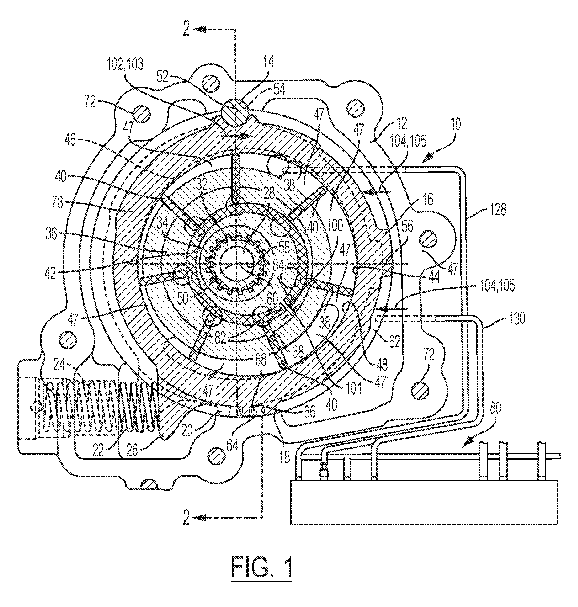
[0017] FIG. 1 is a plan view of an example, non-limiting variable displacement pump (with the cover removed) according to the present disclosure.
[0018] FIG. 2 is a sectional view taken along line 2-2 in FIG. 1
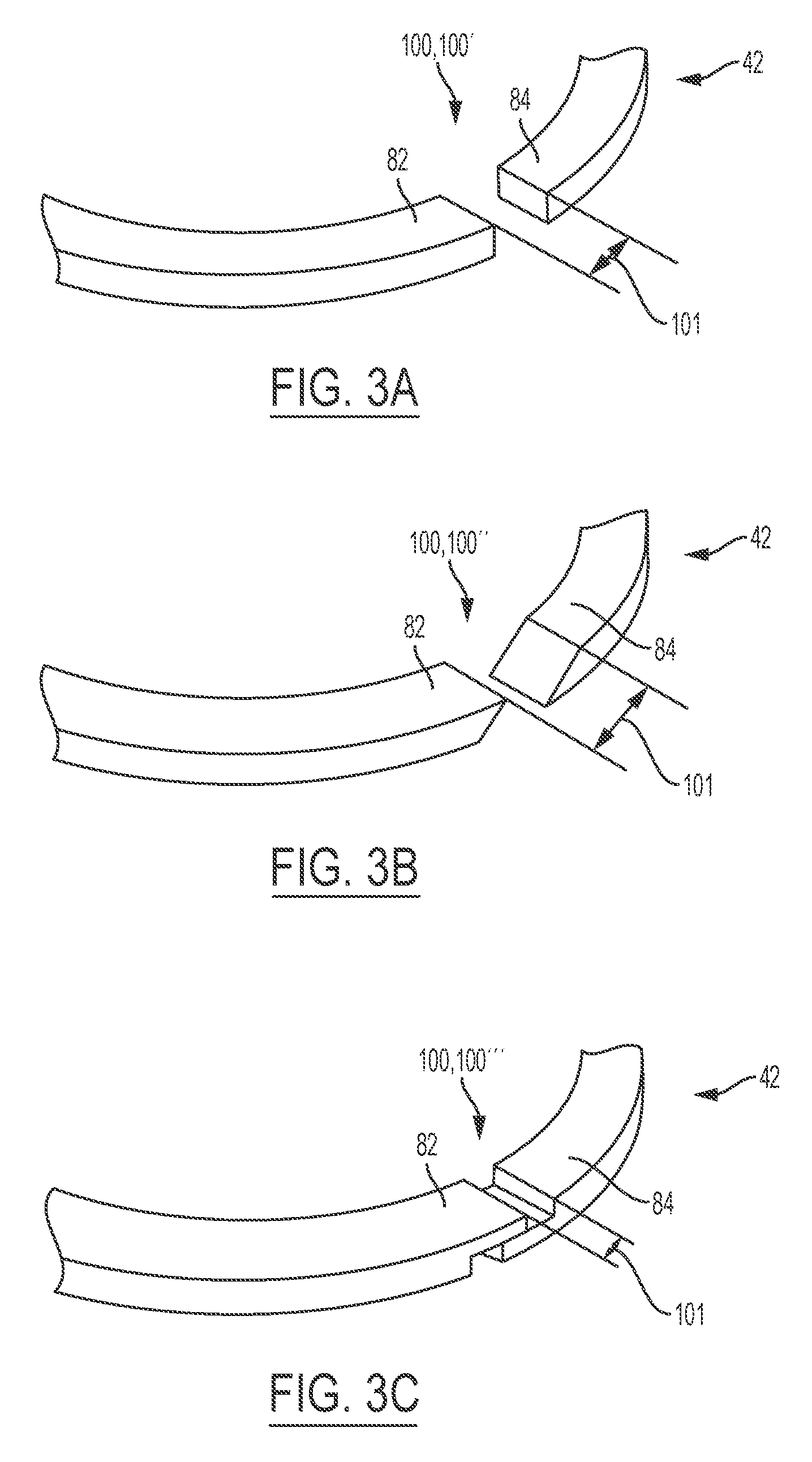
[0019] FIG. 3A is a partial isometric view of a first example expandable vane control ring in accordance with the present disclosure.
[0020] FIG. 3B is a partial isometric view of a second example expandable vane control ring in accordance with the present disclosure.
[0021] FIG. 3C is a partial isometric view of a third example expandable vane control ring in accordance with the present disclosure.
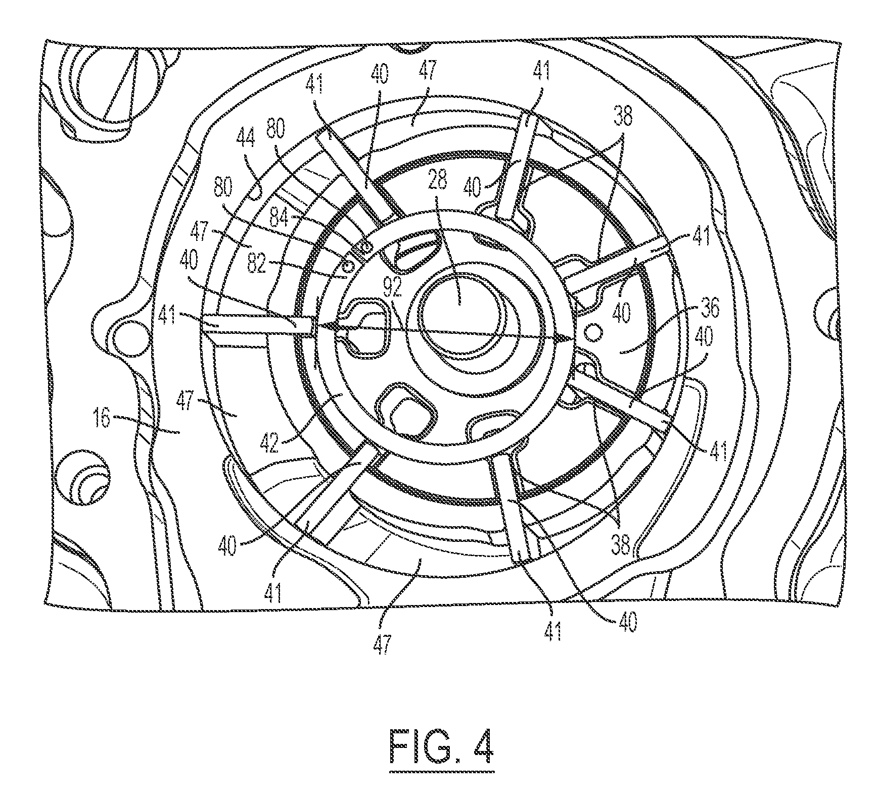
[0022] FIG. 4 is a partial plan view of another example, non-limiting variable displacement pump (with the cover removed) wherein apertures are defined at each end of the expandable vane control ring.
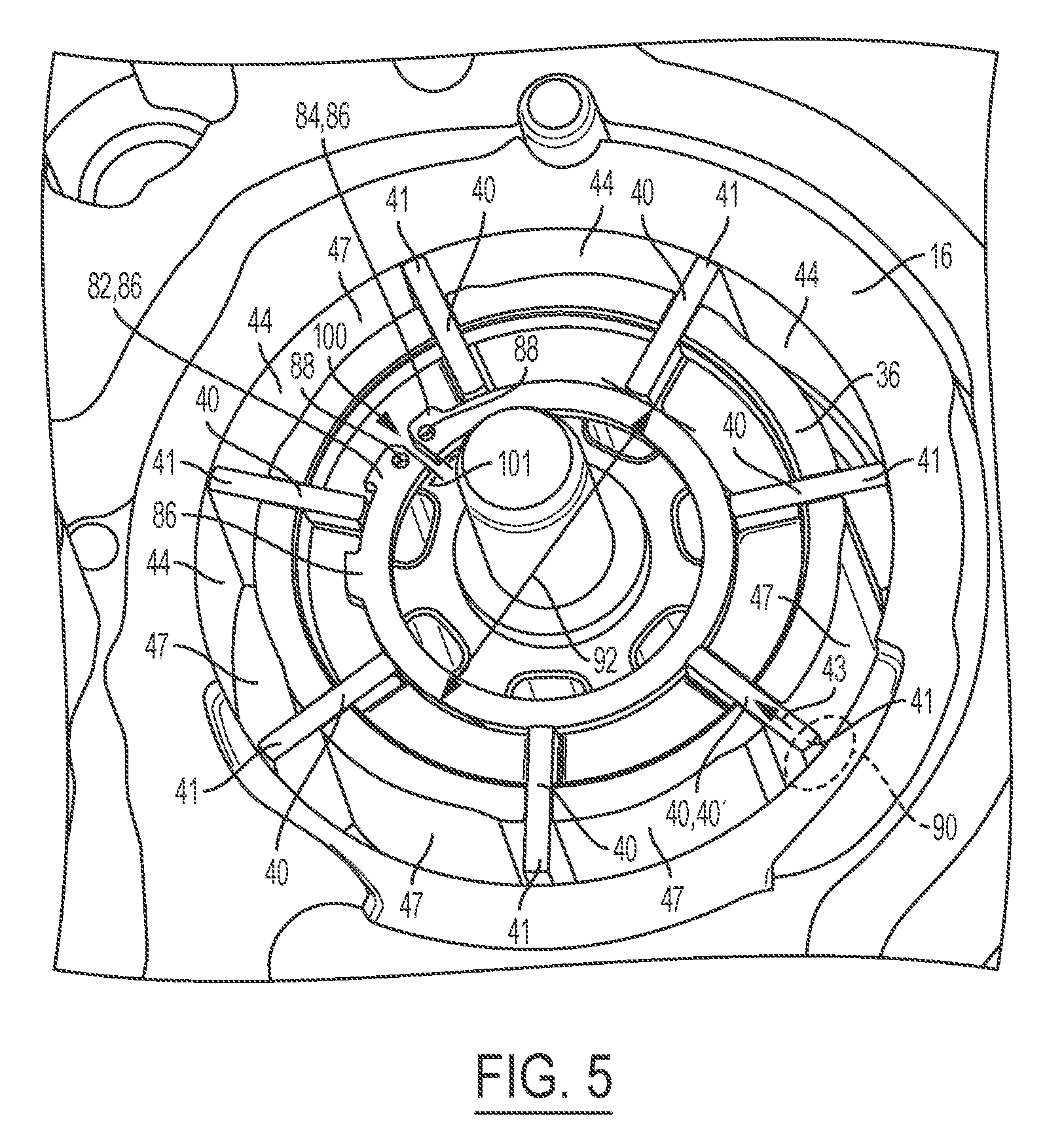
[0023] FIG. 5 is a partial plan view of yet another example, non-limiting variable displacement pump (with the cover removed) wherein anti-rotation tabs and apertures are defined at each end of the expandable vane control ring.
[0024] FIG. 6 is a partial plan view of a traditional vane pump.
[0025] Like reference numerals refer to like parts throughout the description of several views of the drawings.
DETAILED DESCRIPTION
[0026] Reference will now be made in detail to presently preferred compositions, embodiments and methods of the present disclosure, which constitute the best modes of practicing the present disclosure presently known to the inventors. The figures are not necessarily to scale. However, it is to be understood that the disclosed embodiments are merely exemplary of the present disclosure that may be embodied in various and alternative forms. Therefore, specific details disclosed herein are not to be interpreted as limiting, but merely as a representative basis for any aspect of the present disclosure and/or as a representative basis for teaching one skilled in the art to variously employ the present disclosure.
[0027] Except in the examples, or where otherwise expressly indicated, all numerical quantities in this description indicating amounts of material or conditions of reaction and/or use are to be understood as modified by the word "about" in describing the broadest scope of the present disclosure. Practice within the numerical limits stated is generally preferred. Also, unless expressly stated to the contrary: percent, "parts of," and ratio values are by weight; the description of a group or class of materials as suitable or preferred for a given purpose in connection with the present disclosure implies that mixtures of any two or more of the members of the group or class are equally suitable or preferred; the first definition of an acronym or other abbreviation applies to all subsequent uses herein of the same abbreviation and applies mutatis mutandis to normal grammatical variations of the initially defined abbreviation; and, unless expressly stated to the contrary, measurement of a property is determined by the same technique as previously or later referenced for the same property.
[0028] It is also to be understood that this present disclosure is not limited to the specific embodiments and methods described below, as specific components and/or conditions may, of course, vary. Furthermore, the terminology used herein is used only for the purpose of describing particular embodiments of the present disclosure and is not intended to be limiting in any way.
[0029] It must also be noted that, as used in the specification and the appended claims, the singular form "a," "an," and "the" comprise plural referents unless the context clearly indicates otherwise. For example, reference to a component in the singular is intended to comprise a plurality of components.
[0030] The term "comprising" is synonymous with "including," "having," "containing," or "characterized by." These terms are inclusive and open-ended and do not exclude additional, un-recited elements or method steps.
[0031] The phrase "consisting of" excludes any element, step, or ingredient not specified in the claim. When this phrase appears in a clause of the lifter body 14 of a claim, rather than immediately following the preamble, it limits only the element set forth in that clause; other elements are not excluded from the claim as a whole.
[0032] The phrase "consisting essentially of" limits the scope of a claim to the specified materials or steps, plus those that do not materially affect the basic and novel characteristic(s) of the claimed subject matter.
[0033] The terms "comprising", "consisting of", and "consisting essentially of" can be alternatively used. Where one of these three terms is used, the presently disclosed and claimed subject matter can include the use of either of the other two terms.
[0034] Throughout this application, where publications are referenced, the disclosures of these publications in their entireties are hereby incorporated by reference into this application to more fully describe the state of the art to which this present disclosure pertains.
[0035] The following detailed description is merely exemplary in nature and is not intended to limit the present disclosure or the application and uses of the present disclosure. Furthermore, there is no intention to be bound by any theory presented in the preceding background or the following detailed description.
[0036] There is seen in FIGS. 1 and 2 a variable displacement pump 10 of the present disclosure includes a housing 12 in which is secured a pivot pin 14. A slider ring 16 is pivotally mounted on the pin 14 and slidably supported at 18 on a surface 20 formed in the housing 12. The slider ring 16 is urged to the position shown in solid lines in FIG. 1 by a compression spring 22 which is disposed in a cylindrical opening 24 formed in the housing 12 and abuts a lug 26 formed on the slider ring 16.
[0037] Referring now to FIG. 2, a pump drive shaft 28 of the present disclosure may be rotatably mounted in the housing 12 through a needle bearing 30, which drive shaft 28 has a splined end 32 drivingly connected to a spline 34 formed on a pump rotor 36. As shown in FIG. 1, the pump rotor 36 has a plurality of radial slots 38 formed therein in each of which slots 38 is slidably disposed a vane member 40. The vanes 40 are urged outwardly by a pair of vane expandable vane control rings 42 (FIGS. 1-5) and centrifugal force toward an inner surface 44 formed on the slider ring 16. As the rotor 36 rotates via the drive shaft 28, a distal end of each vane abuts and slides against the inner surface 44 of the slider ring 16. However, in a traditional variable vane pump 110 (FIG. 6), a fixed control ring 142 is provided wherein the fixed control ring 142 is continuous (does not include a gap) and has a fixed diameter (not shown). Accordingly, as the vanes 140 are rotated in a traditional variable vane pump 110 as shown in FIG. 6, intermittent friction 90 may be experienced wherein a vane 140 may be temporarily wedged (at the distal end 141 of the vane 140) against the inner surface of the ring 116 such that chatter, noise, and vibration occurs within a traditional variable vane pump. The lack of continuous movement in a traditional variable vane pump also reduces the traditional pump's efficiency.
[0038] Therefore, referring back to FIG. 1, with respect to a variable vane pump 10 of the present disclosure, a housing 12 is included which defines discharge port 46 and inlet port 48 for the pump 10. As shown in FIG. 1, a plurality of pumping chambers 47 are formed by the vanes 40, rotor 36 and surface 44. The chambers 47 rotate with rotor 36 and expand and contract during rotation. The inlet port 48 accepts fluid from a reservoir, not shown, as a vacuum is generated in the expanding chamber 47' and passes the fluid to the other chambers 47. The vanes 40 carry the fluid in the chambers 47 from the inlet port 48 to the discharge port 46. As can be seen in FIG. 1, if the pump rotor 36 may continuously rotate in a counterclockwise direction free from intermittent friction, such that the chambers 47 are continually expanding, to take in fluid, in the area of inlet port 48 and are contracting, to discharge fluid, in the area of the discharge port 46.
[0039] The drive shaft 28 has a central axis 50 which is intersected by an axis 52 passing through the central axis 54 of the pivot pin 14. The axes 52 and 50 are intersected by an axis 56 which is disposed at right angles to the axis 52. In the slider ring's 16 position shown by solid lines in FIG. 1, the center of the inner surface 44 of slider ring is located at 58. However, when the slider ring 16 is moved to the minimum displacement, as shown by phantom lines, the center of inner surface 44 of slider ring is located at 60.
[0040] The position of slider ring 16 is established by control pressure in a chamber 62 which extends about the outer circumference of ring 16 from pivot pin 14 to a seal member 64 disposed in a groove 66 formed in the slider ring 16. Thus, the control fluid is confined to what is essentially a semi-cylindrical chamber 62. The spring (or biasing means) 22 acts in opposition to the control fluid in chamber 62 such that as the pressure in control chamber 62 increases, the pump ring 16 will be moved clockwise about pivot pin 14. The left face, as seen in FIG. 2, of the slider ring 16, rotor 36 and chambers 47 are closed by a cover 70 which is secured to the housing 12 by a plurality of fasteners 72. Leakage from the chambers 47 radially outwardly past the cover 70 is prevented by a seal ring 74 (shown in FIGS. 1-2) disposed in a groove 76 (shown in FIGS. 1-2) formed in the slider ring 16 and urged toward the cover by a resilient backing ring 78. Any fluid leakage which occurs in a radially inward direction passes through the bearing 30.
[0041] The fluid pressure in control chamber 62 is supplied by a regulator valve generally designated 80. As the pressure is developed in chamber 62 via the regulator valve 80, the pump ring 16 will pivot about pin 14 in a clockwise direction against spring 22 thereby reducing the eccentricity between the central axis 50 of rotor 36 and the central axis of the inner surface 44. Thus, the central axis of inner surface 44 will be moved from position 58 toward position 60. When the axis reaches the position 60, the minimum pump displacement has been achieved and the fluid supplied at this point is sufficient to satisfy torque converter flow requirements, transmission lubrication requirements and leakage which occurs in the system.
[0042] Under most operating conditions, the axis of inner surface 44 will be at position 58 during low speed conditions and at position 60 during high speed conditions. As the vanes 40 are rotated from the inlet port 48 to discharge port 46 and vice versa, a pressure transition takes place with the chambers 47. The pressure transition occurs along a line which passes through the central axis 50 of rotor 36 and the axis of inner surface 44. It is also understood that as the vanes 40 are rotated, intermittent friction may be experienced between the inner surface and any vane 40 in the plurality of vanes thereby causing chatter, noise, and vibration.
[0043] Therefore, as shown in FIG. 1, the present disclosure provides a first embodiment variable displacement vane pump 10 which eliminates chatter, noise, and vibration at the interface between the vanes 40 and the slider ring 16 while also improving pump efficiency. The variable displacement vane pump 10 includes a housing 12, an expandable vane control ring 42, a rotor 36, a plurality of vanes 40, a slider ring 16, and a biasing means 22. The expandable vane control ring 42 further includes a pair of ends 82, 84 and defines a gap 100 having a gap width 101 (FIGS. 3A-3C, and FIG. 5) which may expand and contract between each end 82, 84. As shown in the non-limiting examples of FIGS. 3A-3C, the first and second ends 82, 84 of the expandable vane control ring 42 may define the gap in a variety of ways such as, but not limited to a straight gap 100' (FIG. 3A), slanted gap 100'' (FIG. 3B), or a stepped gap 100''' (FIG. 3C). Therefore, the expandable vane control ring 42 (in addition to gap width 101 and gap 100) is configured to temporarily contract when an intermittent friction 90 (FIG. 5) is experienced between the inner surface 44 and any affected vane 40' in the plurality of vanes 40. Moreover, while noting that the expandable vane control ring 42 has the capability to contract, it is understood that the expandable vane control ring 42 is also outwardly/radially biased such that the distal end 41 of each vane 40 in the plurality of vanes 40 maintains contact with the inner surface 44 of the slider ring 16.
[0044] The expandable vane control ring 42 further includes an expandable diameter 92 (FIGS. 4-5) which may increase when the gap width 101 increases. The expandable diameter 92 may also decrease when the gap width 101 decreases. The rotor 36 may be coaxially aligned with a drive shaft 28 and rotatably driven by the drive shaft 28. The plurality of vanes 40 may be slidably disposed in the rotor 36. The slider ring 16 may be pivotally affixed to the housing 12 via a pivot 14. The slider ring 16 may cooperate with the expandable vane control ring(s) 42, the rotor 36 and the vanes 40 to form a plurality of pumping chambers 47. The biasing means 22 may act on the slider ring 16 and urge the slider ring 16 in a first direction 102 via a first force 103. Therefore, the expandable vane control ring 42 enables the distal end 41 of each vane 40 in the plurality of vanes 40 to abut and continuously slide along the inner surface 44 of the slider ring 16 when the rotor 36 rotates within the slider ring 16.
[0045] Therefore, it is understood that the gap 100 of the expandable vane control ring 42 decreases when the expandable diameter 92 (FIGS. 4-5) of the expandable vane control ring 42 also decreases which generally occurs when any intermittent friction 90 (FIG. 6) is experienced by at least one affected vane 40' (FIGS. 1-2, and FIGS. 4-5) in the plurality vanes 40 at the interface with the inner surface 44 of the slider ring 16. The intermittent friction 90 generates a load 43 (FIG. 5) through the affected vane 40' toward the expandable vane control ring 42 thereby causing the expandable vane control ring to contract (such that gap 100 and gap width 101 decreases) and thus, eliminating any intermittent friction. Similarly, it is understood that once any intermittent friction 90 ceases to exist between any vane 40 and the inner surface 44 of the slider ring 16, the expandable vane control ring 42 is biased to expand such that the gap 100 of the expandable vane control ring 42 increases to a predetermined unloaded width 111 (FIG. 5) while the expandable diameter 92 of the expandable vane control ring 42 also increases. Given that the expandable vane control ring 42 is outwardly/radially biased, the distal end 41 of each vane 40 in the plurality of vanes 40 maintains contact with the inner surface 44 of the slider ring 16 which also eliminates chatter between the vanes 40 and the slider ring 16.
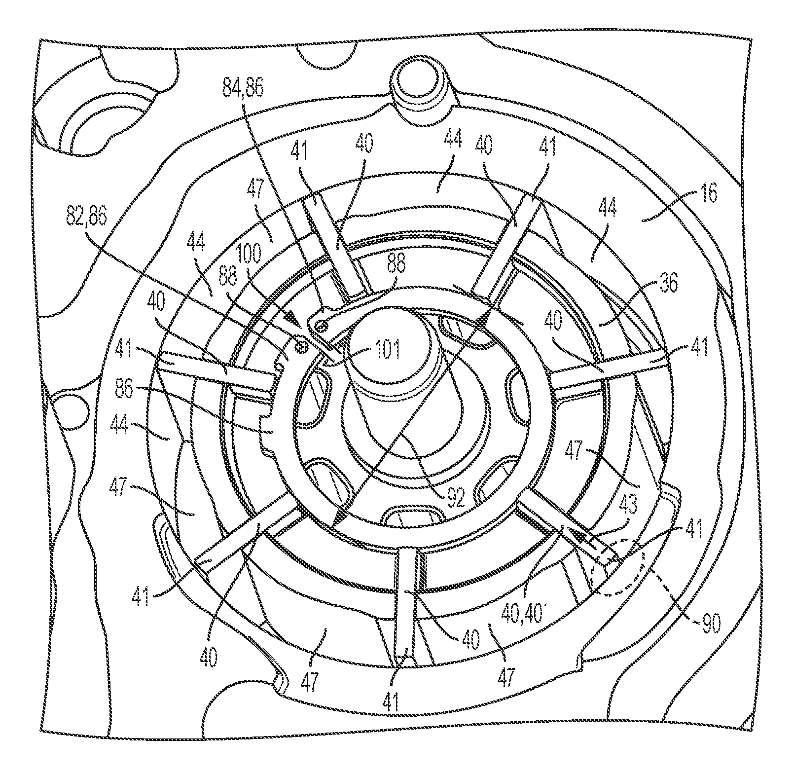
[0046] As further illustrated in FIG. 5, in one non-limiting example, the expandable vane control ring 42 may further define a plurality of anti-rotation tabs 86 configured to prevent a vane 40 in the plurality of vanes 40 from engaging with the gap 100. An anti-rotation tab 86 may or may not be defined at each end 82, 84 of the expandable vane control ring 42--adjacent to or proximate to the gap 100. It is also understood that an aperture 88 may, but not necessarily, also be defined in each tab 86 disposed at each end 82, 84 of the expandable vane control ring 42. Each aperture 88 may be configured to engage with an assembly tool aid.
[0047] In yet another non-limiting example shown in FIG. 4, the expandable vane control ring 42 may further define apertures 88 at each end 82, 84 of the expandable vane control ring 42 wherein anti-rotation tabs 86 are not provided at each end. Similarly, each aperture 88 may be configured to engage with an assembly tool aid and may be defined proximate to each end 82, 84 of the expandable vane control ring 42.
[0048] In yet another embodiment of the present disclosure, a variable displacement vane pump 10 may include a housing 12, an expandable vane control ring 42, a rotor 36, a plurality of vanes 40, and a slider ring 16. The housing 12 may define an inlet port 48 and a discharge port 46. The expandable vane control ring 42 may define a gap 100 and an expandable diameter 92. The rotor 36 may be driven by a drive shaft 28 and coaxially aligned the drive shaft 28. The plurality of vanes 40 may be slidably disposed in the rotor 36. The slider ring 16 may be pivotally affixed to the housing 12 via a pivot 14. The slider ring 16 may further a define a displacement control region 62 with a first portion of the housing 12. The slider ring 16 cooperates with the expandable vane control ring 42, the rotor 36, and the vanes 40 to form a plurality of pumping chambers 47 which are successively connected to the inlet and discharge ports 46, 48. The biasing means 22 may act on the slider ring 16 urging the slider ring 16 in a first direction 102 via a first force 103. Furthermore, a control unit/regulator valve 80 may be provided to generate a varying input working fluid pressure via an input working fluid flow to the displacement control region 62 thereby generating a second force 104 on the slider ring 16 about the pivot means 14 in a second direction 105 opposite to the first direction 102. The second force 104 may be configured to vary relative to the first force 103 (second force 104 being greater than the first force 103 or less than the first force 103) so as vary the volume/size of each pumping chamber 47 and vary the expandable diameter 92 of the expandable vane control ring 42 by pivoting the slider ring 16 back and forth (between the first direction 102 and second direction 105) while the rotor 36 and vanes 40 rotate via the drive shaft 28.
[0049] Referring now to FIG. 5, the expandable vane control ring 42 further includes a pair of ends 82, 84 (first end 82 and second end 84) and defines a gap 100 and a gap width 101 between the first and second ends 82, 84 which may expand and contract. Therefore, the expandable vane control ring 42 is configured to temporarily contract when an intermittent friction 90 is experienced between the inner surface 44 and any vane 40 in the plurality of vanes 40. The expandable vane control ring 42 may further include an expandable diameter 92 which may increase when the gap 100 increases. (The expandable diameter 92 may decrease when the gap 100 decreases.) Regardless, as previously noted, it is understood that the expandable vane control ring 42 is also outwardly/radially biased such that the distal end 41 of each vane 40 in the plurality of vanes 40 maintains contact with the inner surface 44 of the slider ring 16. By eliminating any gaps between the distal ends 41 of the vanes 40 and the inner surface 44 of the slider ring 16, chatter within the pump 10 is also significantly reduced.
[0050] With further reference to FIG. 5, the rotor 36 of a pump 10 according to the present disclosure may be coaxially aligned with a drive shaft 28 and rotatably driven by the drive shaft 28. The plurality of vanes 40 may be slidably disposed in the rotor 36. The slider ring 16 may be pivotally affixed to the housing 12 via a pivot 14. The slider ring 16 may cooperate with the expandable vane control ring 42, the rotor 36 and the vanes 40 to form a plurality of pumping chambers 47. The biasing means 22 may act on the slider ring 16 and urge the slider ring 16 in a first direction 102 via a first force 103. Therefore, the expandable vane control ring 42 enables the distal end 41 of each vane 40 in the plurality of vanes 40 to abut and continuously slides along an inner surface 44 of the slider ring 16 when the rotor 36 rotates within the slider ring 16.
[0051] Therefore, it is understood that the gap 100 and gap width 101 (FIG. 5) of the expandable vane control ring 42 decreases when the expandable diameter 92 of the expandable vane control ring 42 also decreases which generally occurs when intermittent friction 90 is experienced by at least one vane 40 in the plurality vanes 40 at the interface with the inner surface 44 of the slider ring 16. Similarly, it is understood that once any intermittent friction 90 ceases to exist between any vane 40 and the inner surface 44 of the slider ring 16, the expandable vane control ring 42 is biased to expand such that the gap 100 of the expandable vane control ring 42 increases while the expandable diameter 92 of the expandable vane control ring 42 also increases.
[0052] In one non-limiting example of the second embodiment, the expandable vane control ring 42 may further define a plurality of anti-rotation tabs 86 (FIG. 5) configured to prevent a vane 40 in the plurality of vanes 40 from engaging with the gap 100. As shown in FIGS. 4-5, an anti-rotation tab 86 may or may not be defined at each end 82, 84 of the expandable vane control ring 42--adjacent to or proximate to the gap 100. It is also understood that an aperture 88 may, but not necessarily, also be defined in each tab 86 disposed at each end 82, 84 of the expandable vane control ring 42. Each aperture 88 may be configured to engage with an assembly tool aid. In yet another non-limiting example of the second embodiment shown in FIG. 4, the expandable vane control ring 42 may further define apertures 88 at each end 82, 84 of the expandable vane control ring 42 wherein anti-rotation tabs 86 are not provided at each end 82, 84. Similarly, each aperture 88 in FIG. 4 may be configured to engage with an assembly tool aid and may be defined proximate to each end 82, 84 of the expandable vane control ring 42.
[0053] While at least one exemplary embodiment has been presented in the foregoing detailed description, it should be appreciated that a vast number of variations exist. It should also be appreciated that the exemplary embodiment or exemplary embodiments are only examples, and are not intended to limit the scope, applicability, or configuration of the disclosure in any way. Rather, the foregoing detailed description will provide those skilled in the art with a convenient road map for implementing the exemplary embodiment or exemplary embodiments. It should be understood that various changes can be made in the function and arrangement of elements without departing from the scope of the disclosure as set forth in the appended claims and the legal equivalents thereof.
* * * * *
D00000
D00001
D00002
D00003
D00004
D00005
D00006
XML
uspto.report is an independent third-party trademark research tool that is not affiliated, endorsed, or sponsored by the United States Patent and Trademark Office (USPTO) or any other governmental organization. The information provided by uspto.report is based on publicly available data at the time of writing and is intended for informational purposes only.
While we strive to provide accurate and up-to-date information, we do not guarantee the accuracy, completeness, reliability, or suitability of the information displayed on this site. The use of this site is at your own risk. Any reliance you place on such information is therefore strictly at your own risk.
All official trademark data, including owner information, should be verified by visiting the official USPTO website at www.uspto.gov. This site is not intended to replace professional legal advice and should not be used as a substitute for consulting with a legal professional who is knowledgeable about trademark law.