Work Vehicle And Method Of Controlling Work Vehicle
HARADA; Muneo ; et al.
U.S. patent application number 16/475160 was filed with the patent office on 2019-11-07 for work vehicle and method of controlling work vehicle. This patent application is currently assigned to KOMATSU LTD.. The applicant listed for this patent is KOMATSU LTD.. Invention is credited to Muneo HARADA, Yutaka ONO.
| Application Number | 20190338495 16/475160 |
| Document ID | / |
| Family ID | 63107384 |
| Filed Date | 2019-11-07 |

| United States Patent Application | 20190338495 |
| Kind Code | A1 |
| HARADA; Muneo ; et al. | November 7, 2019 |
WORK VEHICLE AND METHOD OF CONTROLLING WORK VEHICLE
Abstract
A first switch valve is connected to a cap-side circuit of a lift cylinder. A second switch valve is connected to a head-side circuit of the lift cylinder. A first accumulator is connected to the cap-side circuit of the lift cylinder with the first switch valve being interposed. A second accumulator is connected to the head-side circuit of the lift cylinder with the second switch valve being interposed. A third switch valve is connected between the first accumulator and the second accumulator.
| Inventors: | HARADA; Muneo; (Minato-ku, Tokyo, JP) ; ONO; Yutaka; (Minato-ku, Tokyo, JP) | ||||||||||
| Applicant: |
|
||||||||||
|---|---|---|---|---|---|---|---|---|---|---|---|
| Assignee: | KOMATSU LTD. Minato-ku, Tokyo JP |
||||||||||
| Family ID: | 63107384 | ||||||||||
| Appl. No.: | 16/475160 | ||||||||||
| Filed: | January 26, 2018 | ||||||||||
| PCT Filed: | January 26, 2018 | ||||||||||
| PCT NO: | PCT/JP2018/002483 | ||||||||||
| 371 Date: | July 1, 2019 |
| Current U.S. Class: | 1/1 |
| Current CPC Class: | E02F 9/2267 20130101; E02F 3/844 20130101; E02F 3/815 20130101; E02F 9/2228 20130101; E02F 9/2285 20130101; E02F 9/2217 20130101; E02F 3/7636 20130101 |
| International Class: | E02F 9/22 20060101 E02F009/22; E02F 3/815 20060101 E02F003/815 |
Foreign Application Data
| Date | Code | Application Number |
|---|---|---|
| Feb 13, 2017 | JP | 2017-023854 |
Claims
1. A work vehicle comprising: a work implement; a cylinder which drives the work implement; a first switch valve connected to a cap-side circuit of the cylinder; a second switch valve connected to a head-side circuit of the cylinder; a first accumulator connected to the cap-side circuit of the cylinder with the first switch valve being interposed; a second accumulator connected to the head-side circuit of the cylinder with the second switch valve being interposed; and a third switch valve connected between the first accumulator and the second accumulator.
2. The work vehicle according to claim 1, the work vehicle further comprising a controller configured to control the first switch valve, the second switch valve, and the third switch valve such that the first switch valve is open and the second switch valve and the third switch valve are closed in a shock absorption mode of the work implement and such that the first switch valve is closed and the second switch valve and the third switch valve are open in a vibration suppression mode of the work vehicle.
3. The work vehicle according to claim 1, the work vehicle further comprising a manual switch which allows selection between a state that the first switch valve is open and the second switch valve and the third switch valve are closed and a state that the first switch valve is closed and the second switch valve and the third switch valve are open.
4. The work vehicle according to claim 1, the work vehicle further comprising a front wheel and a rear wheel, wherein the work implement is arranged between the front wheel and the rear wheel.
5. The work vehicle according to claim 4, wherein the work implement is at least one of a blade and a scarifier.
6. The work vehicle according to claim 1, the work vehicle further comprising a front wheel and a rear wheel, wherein the work implement is arranged at least one of a position in front of the front wheel and a position in rear of the rear wheel.
7. The work vehicle according to claim 6, wherein the work implement is at least one of a front blade and a ripper.
8. The work vehicle according to claim 1, the work vehicle being a grader.
9. A method of controlling a work vehicle, the work vehicle including a work implement, a cylinder which drives the work implement, a first switch valve connected to a cap-side circuit of the cylinder, a second switch valve connected to a head-side circuit of the cylinder, a first accumulator connected to the cap-side circuit of the cylinder with the first switch valve being interposed, a second accumulator connected to the head-side circuit of the cylinder with the second switch valve being interposed, and a third switch valve connected between the first accumulator and the second accumulator, the method comprising: controlling the first switch valve to open and controlling the second switch valve and the third switch valve to close in a shock absorption mode of the work implement and controlling the first switch valve to close and controlling the second switch valve and the third switch valve to open in a vibration suppression mode of the work vehicle.
Description
TECHNICAL FIELD
[0001] The present invention relates to a work vehicle and a method of controlling a work vehicle.
BACKGROUND ART
[0002] A motor grader does not have a suspension function in its undercarriage in order to ensure working performance in such works as land-grading works, road cutting works, and excavation works. In addition, the motor grader includes hollow tires. Therefore, the tires serve as a spring system and vibration occurs in a vehicular body around a specific vehicle speed. When the vehicular body vibrates, a vehicle speed should be lowered in order to avoid vibration during travel.
[0003] For example, Japanese Utility Model Laying-Open No. 2-132754 discloses a technique for suppressing vibration. A motor grader in this literature includes a blade lift cylinder connected to a work implement, a switch valve connected to a cap side of the blade lift cylinder, a switch valve connected to a head side of the blade lift cylinder, and an accumulator connected to the two switch valves.
[0004] In the literature, when a head-side hydraulic circuit of the blade lift cylinder and the accumulator communicate with each other, vibration of the vehicular body during travel of the motor grader is suppressed. Alternatively, when a cap-side hydraulic circuit of the blade lift cylinder and the accumulator communicate with each other, vertical impact on the work implement during works by the motor grader is suppressed.
CITATION LIST
Patent Literature
[0005] PTL 1: Japanese Utility Model Laying-Open No. 2-132754
SUMMARY OF INVENTION
Technical Problem
[0006] A capacity of an accumulator required for suppression of vibration during travel, however, may be higher than a capacity of the accumulator required for suppression of vertical impact on a work implement. In this case, when the capacity of the accumulator is adapted to the capacity required for suppression of vertical impact on the work implement, the accumulator is unable to sufficiently absorb vibration during travel.
[0007] On the other hand, when the capacity of the accumulator is increased in order to sufficiently absorb vibration during travel, force with which a blade (work implement) presses a road surface during works becomes weaker. Then, desired road cutting capability cannot be obtained.
[0008] An object of the present disclosure is to provide a work vehicle capable of obtaining desired working capability while sufficiently suppressing vibration during travel and a method of controlling a work vehicle.
Solution to Problem
[0009] A work vehicle in the present disclosure includes a work implement, a cylinder, a first switch valve, a second switch valve, a first accumulator, a second accumulator, and a third switch valve. The cylinder drives the work implement. The first switch valve is connected to a cap-side circuit of the cylinder. The second switch valve is connected to a head-side circuit of the cylinder. The first accumulator is connected to the cap-side circuit of the cylinder with the first switch valve being interposed. The second accumulator is connected to the head-side circuit of the cylinder with the second switch valve being interposed. The third switch valve is connected between the first accumulator and the second accumulator.
[0010] A method of controlling a work vehicle in the present disclosure is a method of controlling the above-described work vehicle, and includes controlling the first switch valve to open and controlling the second switch valve and the third switch valve to close in a shock absorption mode of the work implement and controlling the first switch valve to close and controlling the second switch valve and the third switch valve to open in a vibration suppression mode of the work vehicle.
Advantageous Effects of Invention
[0011] According to the present disclosure, a work vehicle capable of obtaining desired working capability while sufficiently suppressing vibration during travel and a method of controlling a work vehicle can be realized.
BRIEF DESCRIPTION OF DRAWINGS
[0012] FIG. 1 is a perspective view schematically showing a construction of a motor grader in one embodiment.
[0013] FIG. 2 is a side view schematically showing the construction of the motor grader in one embodiment.
[0014] FIG. 3 is a schematic diagram showing a construction in Comparative Example 1.
[0015] FIG. 4 is a schematic diagram showing a construction in Comparative Example 2.
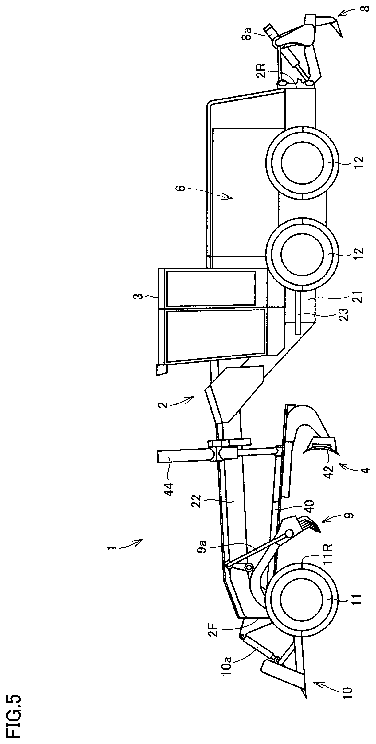
[0016] FIG. 5 is a side view of a motor grader showing other exemplary work implements included in the motor grader in one embodiment.
DESCRIPTION OF EMBODIMENTS
[0017] A work vehicle according to an embodiment of the present disclosure will be described below with reference to the drawings. The same elements have the same reference characters allotted in the description below and their labels and functions are also the same. Therefore, detailed description thereof will not be repeated.
[0018] A construction of a motor grader representing one example of a work vehicle to which the concept of the present disclosure is applicable will initially be described.
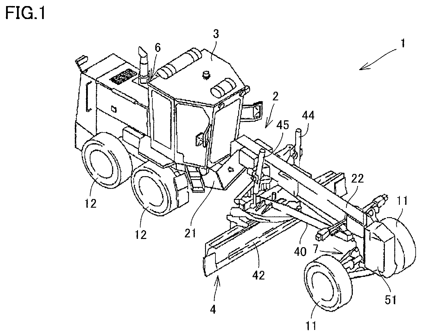
[0019] FIG. 1 is a perspective view schematically showing a construction of a motor grader in one embodiment of the present disclosure. FIG. 2 is a side view schematically showing the construction of the motor grader in one embodiment of the present disclosure.
[0020] As shown in FIGS. 1 and 2, a motor grader 1 in the present embodiment mainly includes running wheels 11 and 12, a vehicular body frame 2, a cab 3, and a work implement 4. Motor grader 1 includes components such as an engine arranged in an engine compartment 6. Work implement 4 includes, for example, a blade 42. Motor grader 1 can do such works as land-grading works, road cutting works, excavation works, snow removal works, and mixing of materials with blade 42.
[0021] Running wheels 11 and 12 include a front wheel 11 and a rear wheel 12. Though FIGS. 1 and 2 show running wheels six in total which consist of two front wheels 11 one on each side and four rear wheels 12 two on each side, the number of front wheels 11 and rear wheels 12 and arrangement thereof are not limited to the example shown in FIGS. 1 and 2.
[0022] In the description of the drawings below, a direction in which motor grader 1 travels in straight lines is referred to as a fore/aft direction of motor grader 1. In the fore/aft direction of motor grader 1, a side where front wheel 11 is arranged with respect to work implement 4 is defined as the fore direction. In the fore/aft direction of motor grader 1, a side where rear wheel 12 is arranged with respect to work implement 4 is defined as the aft direction. A lateral direction of motor grader 1 is a direction orthogonal to the fore/aft direction in a plan view. A right side and a left side in the lateral direction in facing front are defined as a right direction and a left direction, respectively. An upward/downward direction of motor grader 1 is a direction orthogonal to the plane defined by the fore/aft direction and the lateral direction. A side in the upward/downward direction where the ground is located is defined as a lower side and a side where the sky is located is defined as an upper side.
[0023] Vehicular body frame 2 extends in the fore/aft direction (the lateral direction in FIG. 2). Vehicular body frame 2 includes a front end 2F in a foremost portion and a rear end 2R in a rearmost portion. Vehicular body frame 2 includes a rear frame 21 and a front frame 22.
[0024] Rear frame 21 supports components such as an engine arranged in engine compartment 6. For example, each of four rear wheels 12 is attached to rear frame 21 and can rotatably be driven by driving force from the engine.
[0025] Front frame 22 is attached in front of rear frame 21. Front frame 22 is pivotably coupled to rear frame 21. Front frame 22 extends in the fore/aft direction. Front frame 22 includes a base end portion coupled to rear frame 21 and a tip end portion opposite to the base end portion. The base end portion of front frame 22 is coupled to the tip end portion of rear frame 21 with a vertically extending central pin being interposed.
[0026] An articulation cylinder 23 is attached between front frame 22 and rear frame 21. Front frame 22 is provided as being pivotable with respect to rear frame 21 owing to extending and retracting of articulation cylinder 23.
[0027] For example, two front wheels 11 are rotatably attached to the tip end portion of front frame 22. Front wheel 11 is attached to front frame 22 as being revolvable owing to extending and retracting of a steering cylinder 7. Motor grader 1 can change its direction of travel owing to extending and retracting of steering cylinder 7.
[0028] Front wheel 11 is attached to front frame 22 without a suspension being interposed. Rear wheel 12 is attached to rear frame 21 without a suspension being interposed. The suspension here means a component constituted of a suspension arm, a spring, and a shock absorber, and does not include elastic force of a tire.
[0029] A counter weight 51 is attached to front end 2F of vehicular body frame 2. Counter weight 51 represents one type of attachments to be attached to front frame 22. Counter weight 51 is attached to front frame 22 in order to increase a downward load to be applied to front wheel 11 to allow steering and to increase a pressing load on blade 42.
[0030] Cab 3 is carried on front frame 22. In cab 3, an operation portion (not shown) such as a steering wheel, a gear shift lever, a lever for controlling work implement 4, a brake, an accelerator pedal, and an inching pedal is provided. Cab 3 may be carried on rear frame 21.
[0031] Work implement 4 mainly includes, for example, a draw bar 40 and blade 42. Draw bar 40 is arranged below front frame 22. Draw bar 40 has a front end portion coupled to the tip end portion of front frame 22 with a ball bearing portion. Draw bar 40 has the front end portion swingably attached to the tip end portion of front frame 22.
[0032] Draw bar 40 has a rear end portion supported on front frame 22 by lift cylinders 44 and 45. Owing to extending and retracting of lift cylinders 44 and 45, the rear end portion of draw bar 40 can move up and down with respect to front frame 22. Draw bar 40 is vertically swingable with an axis along a direction of travel of the vehicle being defined as the center, as a result of extending and retracting of lift cylinders 44 and 45.
[0033] Blade 42 is arranged between front wheel 11 and rear wheel 12. Front wheel 11 is arranged in front of blade 42. Rear wheel 12 is arranged in the rear of blade 42. Blade 42 is arranged between front end 2F of vehicular body frame 2 and rear end 2R of vehicular body frame 2. Blade 42 is supported on draw bar 40. Blade 42 is supported on front frame 22 with draw bar 40 being interposed.
[0034] As set forth above, blade 42 is constructed to be able to move up and down with respect to the vehicle with draw bar 40 being interposed.
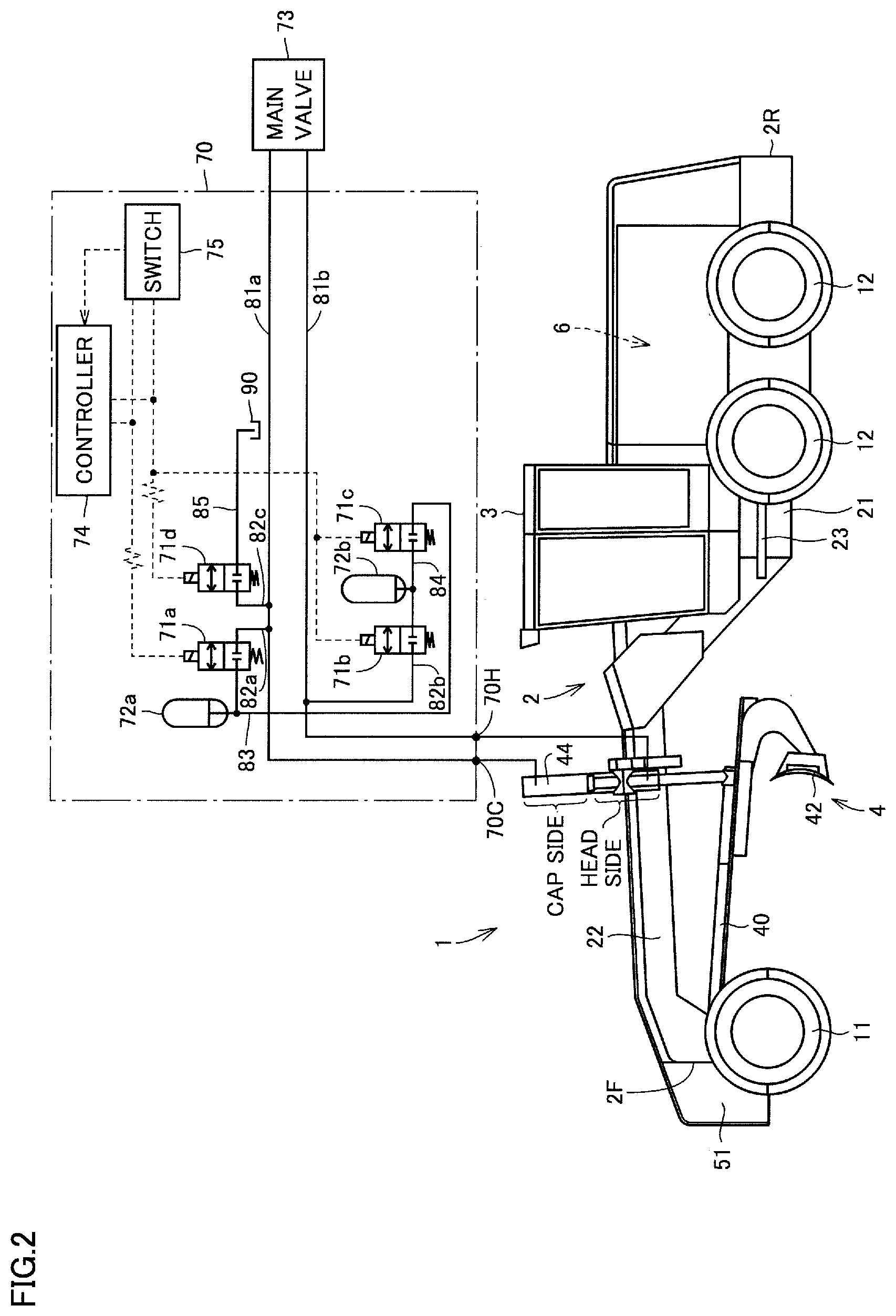
[0035] A shock absorption and vibration suppression mechanism which absorbs vertical impact on a work implement during works and suppresses vibration of a vehicular body during travel in the present embodiment will now be described with reference to FIG. 2.
[0036] As shown in FIG. 2, a shock absorption and vibration suppression mechanism 70 mainly includes a first switch valve 71a, a second switch valve 71b, a third switch valve 71c, a fourth switch valve 71d, a first accumulator 72a, a second accumulator 72b, a controller 74, and a switch 75.
[0037] First switch valve 71a is connected to a cap-side circuit of lift cylinder 44. Second switch valve 71b is connected to a head-side circuit of lift cylinder 44. First accumulator 72a is connected to the cap-side circuit of lift cylinder 44 with first switch valve 71a being interposed. Second accumulator 72b is connected to the head-side circuit of lift cylinder 44 with second switch valve 71b being interposed. Third switch valve 71c is connected between first accumulator 72a and second accumulator 72b.
[0038] A main valve 73 is connected to the cap-side circuit of lift cylinder 44 through an oil path 81a. Main valve 73 is connected to the head-side circuit of lift cylinder 44 through an oil path 81b. First switch valve 71a is connected to an oil path 82abranched from oil path 81a. Second switch valve 71b is connected to an oil path 82b branched from oil path 81b.
[0039] First switch valve 71a and third switch valve 71c are connected to each other through an oil path 83. First accumulator 72a is connected to oil path 83. Second switch valve 71b and third switch valve 71c are connected to each other through an oil path 84. Second accumulator 72b is connected to oil path 84.
[0040] Fourth switch valve 71d is connected to the cap-side circuit of lift cylinder 44. Fourth switch valve 71d is connected to the cap-side circuit of lift cylinder 44 through an oil path 82c branched from oil path 81a. Fourth switch valve 71d is connected to an oil tank 90 through an oil path 85.
[0041] Each of first to fourth switch valves 71a to 71d is electrically connected, for example, to controller 74. Each of first to fourth switch valves 71a to 71d performs an opening and closing operation, for example, based on a control signal from controller 74.
[0042] While first switch valve 71a is open, first accumulator 72a is connected to the cap-side circuit of lift cylinder 44. Alternatively, while first switch valve 71a is closed, first accumulator 72a and the cap-side circuit of lift cylinder 44 are disconnected from each other.
[0043] While first switch valve 71a is open and third switch valve 71c is open, both of first accumulator 72a and second accumulator 72b are connected to the cap-side circuit of lift cylinder 44. Alternatively, while first switch valve 71a is open and third switch valve 71c is closed, first accumulator 72a is connected to the cap-side circuit of lift cylinder 44 whereas second accumulator 72b and the cap-side circuit of lift cylinder 44 are disconnected from each other.
[0044] While second switch valve 71b is open, second accumulator 72b is connected to the head-side circuit of lift cylinder 44. Alternatively, while second switch valve 71b is closed, second accumulator 72b and the head-side circuit of lift cylinder 44 are disconnected from each other.
[0045] While second switch valve 71b is open and third switch valve 71c is open, both of second accumulator 72b and first accumulator 72a are connected to the head-side circuit of lift cylinder 44. Alternatively, while second switch valve 71b is open and third switch valve 71c is closed, second accumulator 72b is connected to the head-side circuit of lift cylinder 44 whereas first accumulator 72a and the head-side circuit of lift cylinder 44 are disconnected from each other.
[0046] Shock absorption and vibration suppression mechanism 70 is controlled, for example, to open first switch valve 71a and close second switch valve 71b and third switch valve 71c in a shock absorption mode of work implement 4. Alternatively, shock absorption and vibration suppression mechanism 70 is controlled, for example, to close first switch valve 71a and open second switch valve 71b and third switch valve 71c in a vibration suppression mode of motor grader 1.
[0047] Switching between the shock absorption mode and the vibration suppression mode may be made by controller 74. Specifically, for example, controller 74 controls first switch valve 71a to open and controls second switch valve 71b and third switch valve 71c to close in the shock absorption mode of work implement 4. Alternatively, for example, controller 74 controls first switch valve 71a to close and controls second switch valve 71b and third switch valve 71c to open in the vibration suppression mode of motor grader 1.
[0048] Alternatively, switching between the shock absorption mode and the vibration suppression mode may be made by switch 75. Switch 75 is implemented, for example, by a manual switch operated manually by an operator. When the operator operates switch 75 to select the shock absorption mode, for example, first switch valve 71a is opened and second switch valve 71b and third switch valve 71c are closed. Alternatively, when the operator operates switch 75 to select the vibration suppression mode, for example, first switch valve 71a is closed and second switch valve 71b and third switch valve 71c are opened.
[0049] Each of first to fourth switch valves 71a to 71d may perform the opening and closing operation upon directly receiving a signal from switch 75. Alternatively, each of first to fourth switch valves 71a to 71d may perform the opening and closing operation upon receiving a command from controller 74 which has received a signal from switch 75.
[0050] Alternatively, each of first to fourth switch valves 71a to 71d may perform the opening and closing operation upon receiving a command from controller 74, regardless of an operation of switch 75. In this case, controller 74 may send a command to each of first to fourth switch valves 71a to 71d based on a signal of at least one of a speed of the work vehicle and a speed stage of a transmission. For example, when the speed stage is set to F6, F7, or F8 or when a vehicle speed attains to 35 km/h or higher, controller 74 may make switching from the shock absorption mode to the vibration suppression mode.
[0051] First shock absorption and vibration suppression mechanism 70 may be connected to lift cylinder 44 shown in FIG. 1 and second shock absorption and vibration suppression mechanism 70 constructed similarly to first shock absorption and vibration suppression mechanism 70 may be connected to lift cylinder 45. Alternatively, a connection portion 70C of single shock absorption and vibration suppression mechanism 70 shown in FIG. 2 may be connected to the cap-side circuit of each of lift cylinders 44 and 45 and a connection portion 70H may be connected to the head-side circuit of each of lift cylinders 44 and 45.
[0052] As shown in FIG. 1, each of first accumulator 72a and second accumulator 72b is attached, for example, to a side portion of front frame 22.
[0053] A method of controlling a work vehicle in the present embodiment will now be described with reference to FIG. 2.
[0054] As shown in FIG. 2, initially, during normal works, each of first to third switch valves 71a, 71b, and 71c is closed. In this state, hydraulic oil is supplied from main valve 73 to lift cylinder 44. Work implement 4 thus moves up and down to perform works.
[0055] The shock absorption mode of work implement 4 is used, for example, when works are performed with blade 42 being engaged with the ground. In the shock absorption mode, first switch valve 71a is opened and second switch valve 71b and third switch valve 71c are closed. As first switch valve 71a is opened, oil path 82a and oil path 83 are connected to each other. First accumulator 72a is thus connected to the cap-side circuit of lift cylinder 44.
[0056] Since second switch valve 71b is closed, oil path 82b and oil path 84 are disconnected from each other. Second accumulator 72b and the head-side circuit of lift cylinder 44 are thus disconnected from each other. Since third switch valve 71c is closed, oil path 84 and oil path 83 are disconnected from each other. First accumulator 72a and the head-side circuit of lift cylinder 44 are thus also disconnected from each other.
[0057] As set forth above, in the shock absorption mode, first accumulator 72a is connected to the cap-side circuit of lift cylinder 44. Therefore, when blade 42 receives shock by colliding with a projection on a road surface such as a rock during works, an air chamber (a space surrounded by a diaphragm) of first accumulator 72a contracts. Shock to work implement 42 is thus absorbed by first accumulator 72a.
[0058] The vibration suppression mode of motor grader 1 is used, for example, while motor grader 1 is traveling and blade 42 is lifted above the ground without being engaged with the ground. In the vibration suppression mode, first switch valve 71a is closed and second switch valve 71b and third switch valve 71c are opened. As first switch valve 71a is closed, oil path 82a and oil path 83 are disconnected from each other. First accumulator 72a and the cap-side circuit of lift cylinder 44 are thus disconnected from each other.
[0059] Since second switch valve 71b is opened, oil path 82b and oil path 84 are connected to each other. Second accumulator 72b is thus connected to the head-side circuit of lift cylinder 44. Since third switch valve 71c is opened, oil path 84 and oil path 83 are connected to each other. First accumulator 72a is thus also connected to the head-side circuit of lift cylinder 44.
[0060] As set forth above, in the vibration suppression mode, both of first accumulator 72a and second accumulator 72b are connected to the head-side circuit of lift cylinder 44. Therefore, work implement 42 is vertically movably held. At this time, a dynamic vibration absorber having a spring effect of each of first accumulator 72a and second accumulator 72b and a damping effect originating from throttling of a hydraulic circuit is implemented and vibration of the vehicular body is suppressed.
[0061] A function and effect of the present embodiment will now be described in comparison to Comparative Example 1 shown in FIG. 3 and Comparative Example 2 shown in FIG. 4.
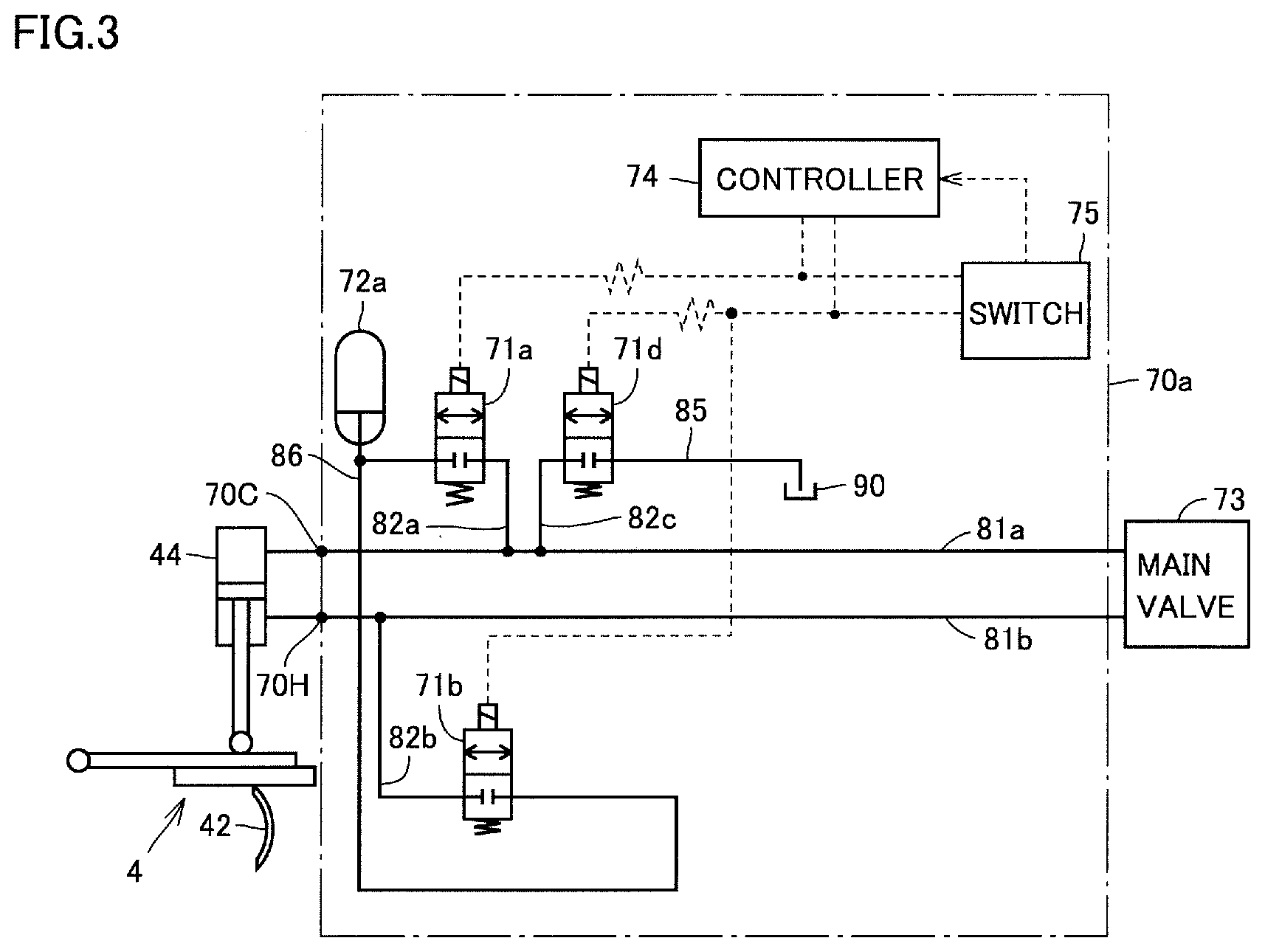
[0062] As shown in FIG. 3, a construction of a shock absorption and vibration suppression mechanism 70a in Comparative Example 1 is different from the construction in FIG. 2 in that third switch valve 71c and second accumulator 72b are not provided. Therefore, accumulator 72a is connected to second switch valve 71b through an oil path 86.
[0063] Since the construction of Comparative Example 1 is otherwise substantially the same as the construction shown in FIG. 2, elements identical to those in the construction shown in FIG. 2 have the same reference characters allotted and description thereof will not be repeated.
[0064] In Comparative Example 1 shown in FIG. 3, in the shock absorption mode, first switch valve 71a is opened and second switch valve 71b is closed so that accumulator 72a can be connected to the cap-side circuit of lift cylinder 44. Alternatively, in the vibration suppression mode, first switch valve 71a is closed and second switch valve 71b is opened so that accumulator 72a can be connected to the head-side circuit of lift cylinder 44.
[0065] In Comparative Example 1, one accumulator 72a is shared between the shock absorption mode and the vibration suppression mode. Therefore, when a capacity required in the vibration suppression mode is higher than a capacity required in the shock absorption mode, accumulator 72a is unable to sufficiently absorb vibration during travel.
[0066] Increase in capacity of accumulator 72a may be possible as a method of overcoming this problem. In this case, however, force with which work implement 42 presses a road surface during works becomes weaker and desired road cutting capability is not obtained.
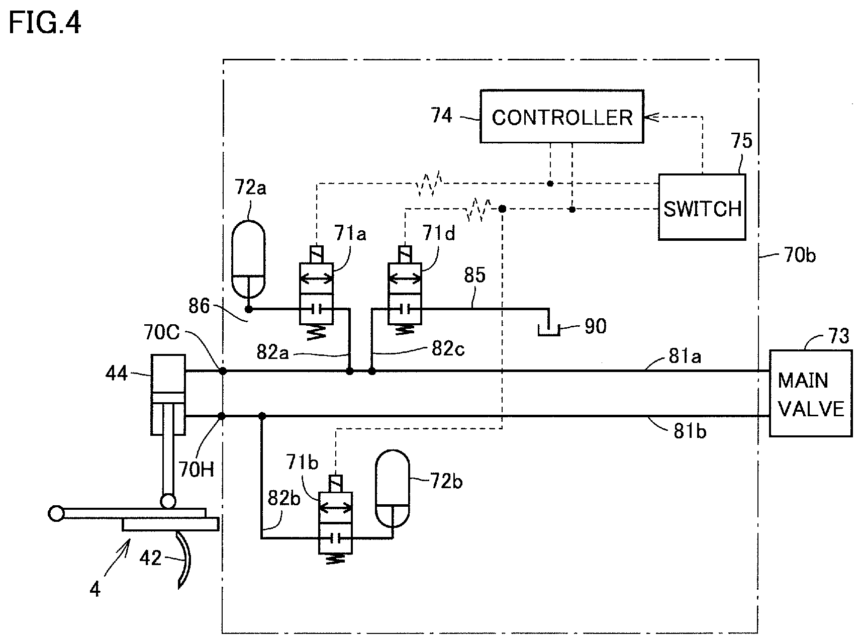
[0067] It is also possible, as the method of overcoming the problem, to individually provide accumulator 72a for absorbing shock and accumulator 72b for suppressing vibration as in a shock absorption and vibration suppression mechanism 70b in Comparative Example 2 shown in FIG. 4. According to this construction, a capacity of accumulator 72a for absorbing shock can be set to a capacity required in the shock absorption mode and a capacity of accumulator 72b for suppressing vibration can be set to a capacity required in the vibration suppression mode.
[0068] In this case, however, two accumulators 72a and 72b high in capacity are required, which leads to increase in size of an apparatus. When each of two accumulators 72a and 72b high in capacity is attached to the side portion of front frame 22 as shown in FIG. 1, front visibility of an operator becomes poor.
[0069] In contrast, as shown in FIG. 2, motor grader 1 in the present embodiment includes first and second accumulators 72a and 72b and first to third switch valves 71a to 71c. Thus, in one of the shock absorption mode and the vibration suppression mode, both of first and second accumulators 72a and 72b can absorb shock or suppress vibration. In the other of the shock absorption mode and the vibration suppression mode, any one of first and second accumulators 72a and 72b alone can absorb shock or suppress vibration.
[0070] Thus, in a mode requiring a relatively low capacity of the accumulator, any one of first and second accumulators 72a and 72b alone can be used. In a mode requiring a relatively high capacity of the accumulator, both of first and second accumulators 72a and 72b can be used.
[0071] A capacity of the accumulator in accordance with each of the two modes can thus be obtained. Therefore, vibration during travel can sufficiently be absorbed in the vibration suppression mode and force with which work implement 42 presses a road surface can also sufficiently be obtained in the shock absorption mode.
[0072] In a mode requiring a relatively high accumulator capacity, both of first and second accumulators 72a and 72b are used. Therefore, only a single accumulator alone does not have to fulfill the relatively high accumulator capacity as in Comparative Example 2. Accordingly, each of first and second accumulators 72a and 72b can be smaller in size than an accumulator in an example in which only a single accumulator alone fulfills a relatively high accumulator capacity. Increase in size of an apparatus can thus be suppressed. Even when each of first and second accumulators 72a and 72b is attached to the side portion of front frame 22, a front field of view of an operator can satisfactorily be kept.
[0073] In the present embodiment, controller 74 controls first to third switch valves 71a to 71c such that first switch valve 71a is open and second and third switch valves 71b and 71c are closed in the shock absorption mode and such that first switch valve 71a is closed and second and third switch valves 71b and 71c are open in the vibration suppression mode.
[0074] Thus, even when a capacity of an accumulator required in the vibration suppression mode is higher than a capacity of an accumulator required in the shock absorption mode, a capacity of the accumulator suitable for both modes can be obtained.
[0075] Specifically, in the shock absorption mode, only first accumulator 72a is connected to the cap-side circuit of lift cylinder 44. Therefore, shock can appropriately be absorbed by first accumulator 72a. In the vibration suppression mode, first and second accumulators 72a and 72b are connected to the head-side circuit of lift cylinder 44. Therefore, even when a capacity of the accumulator required for suppression of vibration is higher than a capacity of the accumulator required for absorption of shock, a total capacity of first and second accumulators 72a and 72b can address such a situation. Therefore, vibration of the vehicular body during travel can sufficiently be suppressed.
[0076] In the present embodiment, selection between the shock absorption mode and the vibration suppression mode may be made by a manual operation of switch 75. Specifically, by manually operating switch 75, selection between a state that first switch valve 71a is open and second and third switch valves 71b and 71c are closed and a state that first switch valve 71a is closed and second and third switch valves 71b and 71c are open may be made.
[0077] Thus, selection between the shock absorption mode and the vibration suppression mode can be made by an operation by an operator.
[0078] Though blade 42 is described above as a work implement to which shock absorption and vibration suppression mechanism 70 is applied, a work implement to which shock absorption and vibration suppression mechanism 70 is applied should only be a work implement arranged between front wheel 11 and rear wheel 12.
[0079] Specifically, as shown in FIG. 5, a work implement to which shock absorption and vibration suppression mechanism 70 is applied may be at least one of blade 42 and a scarifier 9. Scarifier 9 is supported on front frame 22 with a hydraulic cylinder 9a being interposed. Hydraulic cylinder 9a allows scarifier 9 to move up and down with respect to front frame 22.
[0080] When shock absorption and vibration suppression mechanism 70 is applied to scarifier 9, connection portion 70C of oil path 81a of shock absorption and vibration suppression mechanism 70 shown in FIG. 2 is connected to the cap-side circuit of hydraulic cylinder 9a. Connection portion 70H of oil path 81b of shock absorption and vibration suppression mechanism 70 shown in FIG. 2 is connected to the head-side circuit of hydraulic cylinder 9a.
[0081] As shock absorption and vibration suppression mechanism 70 is applied to the work implement arranged between front wheel 11 and rear wheel 12 (for example, blade 42 or scarifier 9), bouncing vibration of motor grader 1 can be suppressed.
[0082] A work implement to which shock absorption and vibration suppression mechanism 70 is applied may be at least one of a work implement arranged in front of front wheel 11 and a work implement arranged in the rear of rear wheel 12.
[0083] Specifically, as shown in FIG. 5, a work implement to which shock absorption and vibration suppression mechanism 70 is applied may be at least one of a front blade 10 and a ripper 8. Front blade 10 is arranged in front of front wheel 11. Front blade 10 is supported on front frame 22 with a hydraulic cylinder 10a being interposed. Hydraulic cylinder 10a allows front blade 10 to move up and down with respect to front frame 22.
[0084] When shock absorption and vibration suppression mechanism 70 is applied to front blade 10, connection portion 70C of oil path 81a of shock absorption and vibration suppression mechanism 70 shown in FIG. 2 is connected to the cap-side circuit of hydraulic cylinder 10a. Connection portion 70H of oil path 81b of shock absorption and vibration suppression mechanism 70 shown in FIG. 2 is connected to the head-side circuit of hydraulic cylinder 10a.
[0085] Ripper 8 is arranged in the rear of rear wheel 12. Ripper 8 is supported on rear frame 21 with a hydraulic cylinder 8a being interposed. Hydraulic cylinder 8a allows ripper 8 to move up and down with respect to rear frame 21.
[0086] When shock absorption and vibration suppression mechanism 70 is applied to ripper 8, connection portion 70C of oil path 81a of shock absorption and vibration suppression mechanism 70 shown in FIG. 2 is connected to the cap-side circuit of hydraulic cylinder 8a. Connection portion 70H of oil path 81b of shock absorption and vibration suppression mechanism 70 shown in FIG. 2 is connected to the head-side circuit of hydraulic cylinder 8a.
[0087] As shock absorption and vibration suppression mechanism 70 is applied to a work implement (for example, front blade 10) arranged in front of front wheel 11 or a work implement (for example, ripper 8) arranged in the rear of rear wheel 12, pitching vibration of motor grader 1 can be suppressed.
[0088] First accumulator 72a and second accumulator 72b in FIG. 2 may be different from each other or identical to each other in capacity. When first accumulator 72a is different in capacity from second accumulator 72b, first accumulator 72a may be higher or lower in capacity than second accumulator 72b.
[0089] A capacity of an accumulator required in the shock absorption mode may be higher than a capacity of an accumulator required in the vibration suppression mode. In the shock absorption mode in this case, controller 74 controls first switch valve 71a and third switch valve 71c to open and controls second switch valve 71b to close in FIG. 2. In the vibration suppression mode in this case, controller 74 controls first switch valve 71a and third switch valve 71c to close and controls second switch valve 71b to open.
[0090] Controller 74 in FIG. 2 controls the switch valves such that only any one of first accumulator 72a and second accumulator 72b is connected to a first circuit of the cap-side circuit and the head-side circuit of work implement hydraulic cylinder 44, 8a, 9a, or 10a in a first mode requiring a relatively low accumulator capacity of the shock absorption mode and the vibration suppression mode. Alternatively, controller 74 controls the switch valves such that both of first accumulator 72a and second accumulator 72b are connected to a second circuit of the cap-side circuit and the head-side circuit of work implement hydraulic cylinder 44, 8a, 9a, or 10a in a second mode requiring a relatively high accumulator capacity of the shock absorption mode and the vibration suppression mode.
[0091] It should be understood that the embodiment disclosed herein is illustrative and non-restrictive in every respect. The scope of the present invention is defined by the terms of the claims rather than the description above and is intended to include any modifications within the scope and meaning equivalent to the terms of the claims.
REFERENCE SIGNS LIST
[0092] 1 motor grader (work vehicle); 2 vehicular body frame; 2F front end; 2R rear end; 3 cab; 4 work implement; 6 engine compartment; 7 steering cylinder; 8 ripper; 8a, 9a, 10a hydraulic cylinder; 9 scarifier; 10 front blade; 11 front wheel; 12 rear wheel; 21 rear frame; 22 front frame; 23 articulation cylinder; 40 draw bar; 42 blade; 44, 45 lift cylinder; 51 counter weight; 70 shock suppression mechanism; 70C, 70H connection portion; 71a first switch valve; 71b second switch valve; 71c third switch valve; 71d fourth switch valve; 72a first accumulator; 72b second accumulator; 73 main valve; 74 controller; 75 switch; 81a, 81b, 82a, 82b, 82c, 83, 84, 85, 86 oil path; and 90 oil tank
* * * * *
D00000
D00001
D00002
D00003
D00004
D00005
XML
uspto.report is an independent third-party trademark research tool that is not affiliated, endorsed, or sponsored by the United States Patent and Trademark Office (USPTO) or any other governmental organization. The information provided by uspto.report is based on publicly available data at the time of writing and is intended for informational purposes only.
While we strive to provide accurate and up-to-date information, we do not guarantee the accuracy, completeness, reliability, or suitability of the information displayed on this site. The use of this site is at your own risk. Any reliance you place on such information is therefore strictly at your own risk.
All official trademark data, including owner information, should be verified by visiting the official USPTO website at www.uspto.gov. This site is not intended to replace professional legal advice and should not be used as a substitute for consulting with a legal professional who is knowledgeable about trademark law.