Paving Train
BUSCHMANN; Martin ; et al.
U.S. patent application number 16/402426 was filed with the patent office on 2019-11-07 for paving train. This patent application is currently assigned to JOSEPH VOEGELE AG. The applicant listed for this patent is JOSEPH VOEGELE AG. Invention is credited to Martin BUSCHMANN, Henning DELIUS, Achim EUL, Arnold RUTZ.
| Application Number | 20190338473 16/402426 |
| Document ID | / |
| Family ID | 62116343 |
| Filed Date | 2019-11-07 |

| United States Patent Application | 20190338473 |
| Kind Code | A1 |
| BUSCHMANN; Martin ; et al. | November 7, 2019 |
PAVING TRAIN
Abstract
A paving train for producing at least one pavement layer on a traffic surface is formed from at least two independently driven units travelling in a group, such as a road finisher, a road paver, an IP finisher, a feeder, a supply unit or the like. The units move one behind the other at a given distance. In order to enable communication between the units via certain parameters such as speed, material filling level and the like, and in order also to easily control a corresponding distance between the units as well as the corresponding material transfer, a wireless communication link is formed between the units at least for exchanging speeds and/or material filling level.
| Inventors: | BUSCHMANN; Martin; (Neustadt, DE) ; RUTZ; Arnold; (Ludwigshafen, DE) ; EUL; Achim; (Mannheim, DE) ; DELIUS; Henning; (Edenkoben, DE) | ||||||||||
| Applicant: |
|
||||||||||
|---|---|---|---|---|---|---|---|---|---|---|---|
| Assignee: | JOSEPH VOEGELE AG Ludwigshafen/Rhein DE |
||||||||||
| Family ID: | 62116343 | ||||||||||
| Appl. No.: | 16/402426 | ||||||||||
| Filed: | May 3, 2019 |
| Current U.S. Class: | 1/1 |
| Current CPC Class: | H04W 4/027 20130101; E01C 2019/207 20130101; G08C 17/02 20130101; G01F 23/0076 20130101; E01C 19/48 20130101; E01C 19/1068 20130101; G08C 17/00 20130101; E01C 2019/2065 20130101; H04W 4/80 20180201; H04W 4/023 20130101; G05D 1/0293 20130101; E01C 2301/04 20130101; H04W 4/46 20180201; H04W 88/085 20130101; G05D 2201/0202 20130101 |
| International Class: | E01C 19/10 20060101 E01C019/10; E01C 19/48 20060101 E01C019/48; G01F 23/00 20060101 G01F023/00; H04W 88/08 20060101 H04W088/08; G08C 17/00 20060101 G08C017/00 |
Foreign Application Data
| Date | Code | Application Number |
|---|---|---|
| May 4, 2018 | EP | 18170768.8 |
Claims
1. A paving train for producing at least one pavement layer on a traffic surface, the paving train comprising: at least two independently drivable units for traveling in a group, which units are movable one behind the other at a predeterminable distance; and a wireless communication system for forming a wireless communication link between the units at least for exchanging speed and/or material level data.
2. The paving train according to claim 1 wherein the at least two units comprise a road finisher, a road paver, an IP finisher, a feeder, or a supply unit.
3. The paving train according to claim 1 wherein at least one of the units has a collision protection.
4. The paving train according to claim 1 wherein the at least two units comprise a finisher and a feeder.
5. The paving train according to claim 4 wherein a paving speed can be predetermined by the finisher and can be changed by the feeder via the wireless communication link.
6. The paving train according to claim 4 wherein a desired paving speed and/or current desired paving speeds can be transmitted to the feeder by the finisher.
7. The paving train according to claim 1 wherein the feeder has a material hopper, and wherein a current speed and/or a filling quantity of the material hopper can be transmitted from the feeder to the finisher.
8. The paving train according to claim 7 wherein the current speed is a material flow rate.
9. The paving train according to claim 1 wherein one of the units is a feeder having at least two material hoppers for receiving different mixed materials.
10. The paving train according to claim 1 wherein one of the units is a feeder having a filling level indicator device.
11. The paving train according to claim 1 wherein sensors are arranged for level measurement.
12. The paving train according to claim 11 Wherein the sensors comprise an ultrasonic sensor, a camera, or a 3D sensor.
13. The paving train according to claim 1 wherein the at least two units comprise a feeder having a material hopper and a time display device for displaying time until a filling quantity present in the material hopper is used up.
14. The paving train according to claim 1 wherein the at least two units comprise two finishers and a feeder assigned to the two finishers, and wherein an operator of the paving train can transmit a current material. stock of each finisher by means of the wireless communication link.
15. The paving train according to claim 14 wherein each finisher has a material hopper and can transmit to the operator at least a filling level and/or an estimated time until a filling quantity of the material hopper is used up.
16. The paving train according to claim 1 wherein the at least two units comprise a finisher having a sensor for measuring a filling level on the finisher.
17. The paving train according to claim 16 Wherein the sensor comprises an ultrasonic sensor, a camera, or a 3D sensor.
18. The paving train according to claim I wherein the wireless communication. system is configured to establish the wireless communication link using WLAN, Bluetooth, ZigBee, Wibree, Wimax, or optical directional radio.
19. The paving train according to claim 1 wherein data can be transmitted in encrypted form by means of the wireless communication link.
20. A paving train for producing at least one pavement layer on a traffic surface, the paving train comprising: at least two independently drivable units for traveling in a group, which units are movable one behind the other at a predeterminable distance; and a wireless communication. system for establishing a wireless communication link between the units for communicating speed and/or material level data.
Description
CROSS-REFERENCE TO RELATED APPLICATIONS
[0001] This application claims foreign priority benefits under 35 U.S.C. .sctn. 119(a)-(d) to European patent application number EP 18170768.8, filed May 4, 2018, which is incorporated by reference in its entirety.
TECHNICAL FIELD
[0002] The disclosure refers to a paving train for the production of at least one pavement layer on a traffic area. Such a paving train consists of two, or more independently driven, units travelling in a group. Such units are, for example, road finishers, road pavers, feeders, supply units or the like. These move one behind the other at a pre-defined distance.
BACKGROUND
[0003] This type of paving train is being used on an increasing number of road construction sites for paving asphalt or the like, where in addition to a road finisher, for example, feeders are also being used for non-contact asphalt transfer to the road finisher. The use of such a feeder and the resulting material buffer allows the asphalt to be paved without interruption. In other words, the road finisher or another finisher can produce the road continuously and the feeder follows the finisher at a pre-defined distance from the material transfer point. This avoids, for example, shocks caused by the docking of trucks.
[0004] It is therefore possible for the feeder to carry different mixes in two or more material buffers in the form of material buckets and transfer them to the finisher.
[0005] It is also possible, for example, for two finishers to be served by one feeder when paving hot on hot. In order to maintain a certain distance between the units in the paving train, it is known in practice that there is a corresponding distance control or a collision protection to control the corresponding distance between finisher and feeder.
[0006] It is also known from practical experience that an operator, in particular of a feeder, estimates how much material is still in the material buffer of the finisher in question or is in the transfer phase and, in the case of two finishers in particular, then has to decide which finisher has to be fed with mix. This also applies to the corresponding distance control, according to which the feeder in particular adapts to the finisher's paving speed. In other words, essentially only the feeder must be equipped with an appropriate distance control so that it can follow the speed of the finisher. As an emergency measure, the drive-on guard can be designed to prevent the feeder from driving too close to the finisher if it is unable to maintain the appropriate distance.
SUMMARY
[0007] The present disclosure is based on the object of enabling appropriate communication of certain parameters, such as speed, material level and the like, and of easily controlling both an appropriate distance between the units and the corresponding material transfer.
[0008] The disclosure is characterized in particular by the fact that a wireless communication link is formed between the units at least for the exchange of speeds and/or material level.
[0009] This means that the use of a wireless communication link can, for example, show an operator of a feeder or finisher how much material is still available in the material hopper or buffer. This makes it easier and better for the operator to decide how much material is to be transferred to which finisher or how much material is still present. In addition, when measuring speeds, it is possible, for example, for the finisher to set the paving speed on site and for the feeder to follow. However, a finisher operator is usually unable to determine directly whether the feeder can still feed the finisher with sufficient material. The wireless communication link, however, allows the paving speed, for example initiated by the feeder, to be slowed down in good time if a corresponding material level at the feeder is relatively low. The wireless communication link can also be used to start the units after a stop or to stop them.
[0010] In addition to the wireless communication link, the respective unit can also have collision protection. as an emergency measure. This prevents, for example, a too small distance between the units in the event of a failure of the wireless communication connection.
[0011] It has already been pointed out that a finisher can be used to set the appropriate paving speed. The feeder then follows or travels ahead of the finisher at the appropriate speed, whereby the finisher can transmit the paving speed to the feeder via the wireless communication link, If, however, the material level at the feeder drops below a specified level, the feeder in particular can change the paving speed via the wireless communication link, and in particular reduce it.
[0012] In addition, embodiments according to the disclosure allow further speeds to be transmitted so that, for example, the finisher can transmit a target paving speed and/or a current target speed to a feeder. By means of this corresponding information via the wireless communication link, the feeder follows or travels ahead of the finisher according to the target paving speed or current target speed.
[0013] It is also possible, for example, to transmit a current speed from the feeder to the finisher via the wireless communication link, so that the finisher can adapt its paving speed to the speed of the feeder if necessary. This information can also be transmitted from the feeder to the finisher via the flowing material flow and/or via a filling quantity in the existing material hopper or buffer. The speed of the finisher can also be adapted to the feeder with regard to these two parameters.
[0014] In addition, by transmitting this data, the current filling quantities of the feeder at the finisher or for the finisher driver are known.
[0015] It can also be advantageous if the feeder has at least two material hoppers or buffers with different mixes. This makes it possible to deliver the respective mix from one of the material buffers to the finisher, whereby the corresponding mix change can also be communicated via the wireless communication link. This also applies to the corresponding quantity in the respective material buffer or material flow.
[0016] The feeder can be equipped with a filling level indicator in order to check the filling quantity in the material hopper or buffer in a simple manner and adapted to the wireless communication link. This means that the feeder driver is always informed about the current filling quantities of the respective material buffer. The corresponding information can also be transmitted to the finisher via the wireless communication link.
[0017] A simple way to measure the filling level and then display it can be seen in the finisher if appropriate sensors are installed, such as ultrasonic sensors, cameras, 3D sensors or the like.
[0018] In order to enable the display not only of the filling level, but also, if necessary, of the time until the corresponding material is used up, the filling level display device can also be designed for time display or a separate time display can be provided next to the filling level display device for displaying the time until the filling quantities present in the material hopper or bullet are used up.
[0019] At this point, it should be noted that a corresponding filling level on the finisher can also be measured using such sensors. A current filling quantity from the finisher can also be available at the feeder, so that the subsequent delivery of material can be adapted accordingly by the feeder. Of course, the finisher operator can also be informed of the finisher's filling level by means of corresponding filling level display devices and/or time displays.
[0020] It is also possible, for example, to assign a feeder to two finishers in particular. This means that by using the wireless communication link, a corresponding feeder driver can be informed which finisher still has how much material available in the material hopper or buffer and, if necessary, when new material should be fed to which finisher. This ensures that the feeder driver always has access to the current filling quantities of the material buffers of both finishers.
[0021] The wireless communication link can be used to transmit parameters such as the respective finisher's filling level and/or estimated time until the filling quantity is used up from the corresponding finisher.
[0022] In order to be able to calculate the corresponding time until the consumption of the filling quantity, flow rates from the past can be used, for example, so that the expected time until the consumption of the corresponding material can be calculated on the basis of the corresponding filling quantities and the flow rates known from the past.
[0023] Various standards are conceivable for the wireless communication connection, such as WLAN, Bluetooth, Zigbee, Wibree, Wimax, free-space optical communication or similar. All these standards have a sufficient range to establish an appropriate wireless communication link between the units of a paving train. In order to avoid external influences of the wireless communication link, it is also possible to transmit the corresponding data in encrypted form via the wireless communication link.
[0024] According to the disclosure, a feeder can also influence the speed of a paving train based on possible material flows and remaining level of material at the feeder, for example. In addition, corresponding parameters can be easily exchanged between finishers and feeders, e.g., in order to query filling levels at all units by means of a corresponding filling level measurement and to display them for each unit. Furthermore, the distance between the units of the paving train is controlled in a simple way, since the paving speed can be changed by each of the units through the wireless communication link through appropriate interaction of all units. This also applies to starting up after a stop, where in this context the current target speed and a corresponding target paving speed of each of the units is available or can be interrogated.
[0025] In the following, advantageous embodiments of the disclosure are explained in more detail with reference to the attached drawings.
BRIEF DESCRIPTION OF THE DRAWINGS
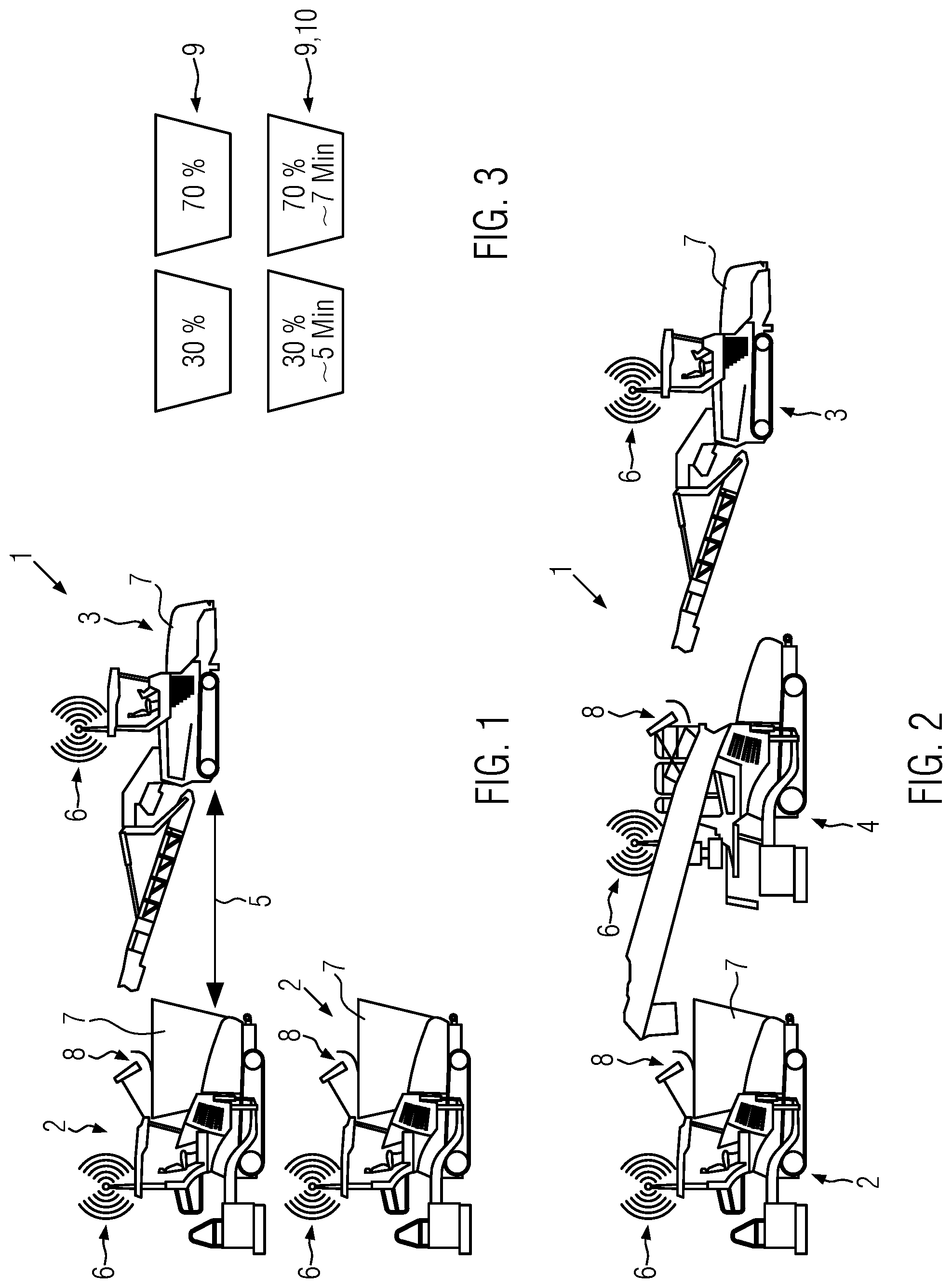
[0026] FIG. 1 shows a paving train consisting of two finishers and a feeder;
[0027] FIG. 2 shows a paving train consisting of road finisher, IP finisher and feeder; and
[0028] FIG. 3 shows the principle of displays for the material filling level or usage time.
DETAILED DESCRIPTION
[0029] FIG. 1 shows a feeder 3 for feeding two road finishers 2. These vehicles form a paving train 1 for producing at least one pavement layer on a traffic area. Each of the units 2, 3 is driven independently and these drive in a group to enable, for example, uninterrupted paving of asphalt. Each of the two finishers 2 has a corresponding material hopper or buffer 7, into which the feeder 3 can deliver additional material. Corresponding filling levels of the material buffers 7 can be determined by a filling level sensor 8, whereby such a filling level sensor is, for example, an ultrasonic sensor, a camera, a 3D sensor or the like. A wireless communication link 6 is established between the units, which can be used, for example, to control a distance 5 between road finisher 2 and feeder 3. Such distance control is achieved, for example, by transmitting a target paving speed or the current target speed from the finisher to the feeder. This means that the feeder follows or travels ahead of the finisher at the appropriate speed in order to maintain the required distance 5. At this distance 5, the finisher can still be loaded with material from the feeder 3.
[0030] Furthermore, in the embodiment shown in FIG. 1, it can be seen via the wireless communication link on the feeder 3 which finisher 2 still has how much material available. Referring also to FIG. 3, the feeder driver is shown how much material is still available in the respective material buffer 7 of the corresponding finisher 2. This enables the feeder driver to determine in good time and reliably how much material should be transported to which finisher and when. This means that the feeder driver can switch from one finisher to another as soon as he has received the relevant information via the wireless communication link. According to the disclosure, the feeder driver therefore always knows the current filling quantity of the two finishers. In addition to the corresponding filling quantity, the feeder driver can also see the estimated time until the existing quantities are used up at the finisher, see again FIG. 3 with the percentage data for the filling level indicator devices 9 or percentage data and time data for the filling level indicator device with time display 9, 10.
[0031] The corresponding times can, for example, be calculated on the basis of the measured filling quantities and flow rates known from the past at the finisher.
[0032] In both FIG. 1 and. FIG. 2, further parameters, such as the finisher's paving speed, are transmitted via the wireless communication link so that the feeder can adapt to the finisher. In addition, a collision protection can be provided between the units of paving train 1, which, for example, prevents the units from being too close together if the wireless communication link fails.
[0033] According to the disclosure, this allows the finisher to set the corresponding speed for the paving train. However, in some cases the finisher driver is unaware of any bottlenecks in the feeding of mix from the feeder. The wireless communication link enables feedback to the finisher driver. This enables the finisher driver to reduce the paving speed. This can also be done by the feeder, as it also has the corresponding displays in FIG. 3 for its material buffers and its material consumption time.
[0034] In addition, the wireless communication link is used to determine the corresponding parameters when starting up after a stop or when stopping the units of the paving train. This can be improved, for example, by transmitting current target speeds between the units. Similarly, the corresponding parameters can also be reported via the wireless communication link from the feeder, e.g., see material level or time till consumption of the material. This means that these parameters can also be used by the finisher to adjust the paving speed according to these parameters.
[0035] In FIG. 2, the corresponding paving train 1 consists of three units, see road finisher 2, Inline-pave (IP) finisher 4 and feeder 3. These can travel one after the other with the appropriate distance control, see the embodiment for FIG. 1, whereby it is also possible to change the arrangement of the units. Here, too, there is a corresponding transmission of parameters between the units, see as parameters the paving speed, nominal paving speed, current nominal speed, material filling levels or time for material consumption. The corresponding wireless communication link 6 exists between all units.
[0036] it should also be noted that it is also possible, for example, for the feeder to have two material buffers with different mixes, so that the corresponding material can be transferred to the finisher as required. This means, for example, that different material can be fed to the different finishers as shown in FIG. 1.
[0037] This also applies analogously to FIG. 2.
[0038] FIG. 3 shows the corresponding displays for two material buffers, for example, see level indicator 9 with 30% and 70% material respectively in the material buffers of two finishers or in two material buffers of a feeder. FIG. 3 also shows a further example where the level indicator 9 also has a time display 10. This shows that, for example, the 30%-filled material buffer can still be fed to the finisher for five minutes, or the 70%-filled material buffer can still be fed for seven minutes. However, this can also be an indication of the time remaining for two different finishers to empty their material buffers.
* * * * *
D00000
D00001
XML
uspto.report is an independent third-party trademark research tool that is not affiliated, endorsed, or sponsored by the United States Patent and Trademark Office (USPTO) or any other governmental organization. The information provided by uspto.report is based on publicly available data at the time of writing and is intended for informational purposes only.
While we strive to provide accurate and up-to-date information, we do not guarantee the accuracy, completeness, reliability, or suitability of the information displayed on this site. The use of this site is at your own risk. Any reliance you place on such information is therefore strictly at your own risk.
All official trademark data, including owner information, should be verified by visiting the official USPTO website at www.uspto.gov. This site is not intended to replace professional legal advice and should not be used as a substitute for consulting with a legal professional who is knowledgeable about trademark law.