Systems And Methods For Electrodepositing Multi-component Alloys, And Products Made From The Same
Maddala; Dharma ; et al.
U.S. patent application number 16/508068 was filed with the patent office on 2019-11-07 for systems and methods for electrodepositing multi-component alloys, and products made from the same. The applicant listed for this patent is ARCONIC INC.. Invention is credited to Andreas Kulovits, Dharma Maddala, Raphael S. Morales, Vivek Sample, Shawn Sullivan, Kelly M. Weiler.
| Application Number | 20190338434 16/508068 |
| Document ID | / |
| Family ID | 62908251 |
| Filed Date | 2019-11-07 |


View All Diagrams
| United States Patent Application | 20190338434 |
| Kind Code | A1 |
| Maddala; Dharma ; et al. | November 7, 2019 |
SYSTEMS AND METHODS FOR ELECTRODEPOSITING MULTI-COMPONENT ALLOYS, AND PRODUCTS MADE FROM THE SAME
Abstract
The present application relates to systems and methods for electrodepositing multi-component alloys, and products made by the same. The electrodeposition may be accomplished to deposit one or more multi-component alloy layers on a substrate. In one embodiment, a substrate is a bulk metal glass. In one embodiment, a substrate is an aluminum alloy substrate. In one embodiment, preconfigured cathode and/or anode configurations are used, which may facilitate, among other things, a uniform current density.
| Inventors: | Maddala; Dharma; (Monroeville, PA) ; Sullivan; Shawn; (Oakmont, PA) ; Sample; Vivek; (Murrysville, PA) ; Kulovits; Andreas; (Pittsburgh, PA) ; Morales; Raphael S.; (Verona, PA) ; Weiler; Kelly M.; (Oakmont, PA) | ||||||||||
| Applicant: |
|
||||||||||
|---|---|---|---|---|---|---|---|---|---|---|---|
| Family ID: | 62908251 | ||||||||||
| Appl. No.: | 16/508068 | ||||||||||
| Filed: | July 10, 2019 |
Related U.S. Patent Documents
| Application Number | Filing Date | Patent Number | ||
|---|---|---|---|---|
| PCT/US2018/014242 | Jan 18, 2018 | |||
| 16508068 | ||||
| 62447840 | Jan 18, 2017 | |||
| Current U.S. Class: | 1/1 |
| Current CPC Class: | C25D 3/56 20130101; C25D 17/007 20130101; C25D 5/10 20130101; C25D 17/12 20130101 |
| International Class: | C25D 3/56 20060101 C25D003/56 |
Claims
1. A method comprising: (a) preparing a surface of the substrate for electrodeposition; (i) wherein the substrate is selected from the group consisting of metallic aluminum and aluminum alloys; (b) placing the substrate in an electrolyte; (c) electrodepositing a first composition on a surface of the substrate, thereby producing a first layer located on at least a portion of the substrate, wherein the first composition is a multi-component alloy.
2. The method of claim 1, wherein the substrate is a lithium-containing aluminum alloy.
3. The method of claim 1, wherein the electrolyte is an organic.
4. The method of claim 1, wherein the electrolyte is aqueous.
5. The method of claim 1, wherein after the electrodepositing step the first layer is adherent to the substrate.
6. The method of claim 1, wherein, after the electrodepositing step, the first layer is absent of pin-hole and blob defects.
7. The method claim 1, wherein the first layer is continuous.
8. A method comprising: (a) placing a bulk metal glass substrate in an electrolyte; (b) electrodepositing a multi-component alloy on the bulk metal glass substrate, thereby producing a multi-component alloy layer located on at least a portion of the bulk metal glass substrate.
9. The method of claim 8, comprising: depositing a second composition on the first layer.
10. The method of claim 9, wherein the second composition is metallic, a metal alloy, or another different multi-component alloy.
11. An electrodeposition system comprising: (a) an electrolyte (b) a anode at least partially disposed in the electrolyte and connected to an external current source; (c) a cathode at least partially disposed in the electrolyte and connected to the external current source; (i) wherein the cathode comprises a non-planar exterior surface; (ii) wherein the anode comprises a predetermined volume and opposing exterior surface that corresponds to the non-planar exterior surface of the cathode.
12. The electrodeposition system of claim 11, wherein the predetermined volume and opposing exterior surface of the anode facilitates a generally uniform current density during electrodeposition operations of the electrodeposition system.
13. The electrodeposition system of claim 11, wherein the anode is dissolvable.
14. The electrodeposition system of claim 11, wherein the anode is non-consumable.
Description
CROSS-REFERENCE TO RELATED APPLICATIONS
[0001] This application is a continuation of International Patent Application No. PCT/US2018/014242, filed Jan. 18, 2018, which claims the benefit of priority to U.S. Provisional Patent Application No. 62/447,840, filed Jan. 18, 2017, each of which is incorporated herein by reference in its entirety.
FIELD OF THE INVENTION
[0002] The present invention relates to systems and methods for electrodepositing multi-component alloys, and producing products made from the same.
BACKGROUND
[0003] The article "Investigation of electrodeposition of Ni--Co--Fe--Zn alloys in DMSO with MHD effect" by Ebadia et al. states "Alloy electrodeposition, is a surface finishing technique which has been used to improve properties such as grain size, hardness, and corrosion resistance compared to the parent metals. The main problem of metal electrodeposition process in an aqueous bath is the Hydrogen Evolution Reaction (HER) which affects the morphology of the electrodeposited surface."
SUMMARY OF THE INVENTION
[0004] Broadly, the present disclosure relates to methods of electrodepositing metals and alloys on substrates, and products produced by the same. In one approach, a method relates to depositing a multi-component alloy on an aluminum or aluminum alloy substrate. In this regard, a method may include the steps of (a) preparing surface of a metallic aluminum or aluminum alloy substrate for electrodeposition, (b) placing the substrate in an electrolyte, and (c) electrodepositing at least a first composition on a surface of the substrate, thereby producing a first layer located on at least a portion of the substrate, wherein the first composition is a multi-component alloy. In one particular embodiment, the substrate is a lithium-containing aluminum alloy. After the electrodeposition step, the first layer comprising the multi-component alloy may be adherent to the metallic aluminum or aluminum alloy substrate. The first layer may also be free of defects, such as pinhole defects and/or and blob defects. The first layer may also be continuous. Thus, the final product may be commercially viable, and comprise a metallic aluminum or aluminum alloy substrate with an adherent, defect-free, continuous multi-component alloy layer thereon. Additional layers (metallic, alloy, or other) may be deposited on this first multi-component alloy layer.
[0005] In another approach, the substrate may be any metallic, metal alloy or multi-component alloy, and may include multiple layers thereon. In one embodiment, a method may include the steps of (a) preparing a surface of a substrate for electrodeposition, (b) first depositing a first composition on a surface of the substrate, thereby producing a first layer located on at least a portion of the substrate, and (c) second depositing a second composition on a surface of the first layer, thereby producing a second layer located on at least a portion of the first layer. In this approach, at least one of the first and second compositions is a multi-component alloy, and at least one of the first and second depositing steps comprises electrodeposition. In one embodiment, the first depositing step comprises electrodeposition. In one embodiment, the first layer is a multi-component alloy, and the second layer is metallic, a metal alloy, or another different multi-component alloy. In another embodiment, the second layer is a multi-component alloy, and the first layer is metallic or a metal alloy. In one embodiment, the second depositing step comprises at least one of spraying, additive manufacturing and electrodeposition.
[0006] In another approach, electrodeposition is used to produce one or more multi-component alloy layers on a bulk metal glass substrate. In one embodiment, a method includes (a) placing a bulk metal glass substrate in an electrolyte, and (b) electrodepositing a multi-component alloy on at least a portion of the bulk metal glass substrate, thereby producing a multi-component alloy layer located on at least a portion of the bulk metal glass substrate. Optionally, one or more other layers may be deposited (e.g., electrodeposited) on this multi-component alloy layer and/or the substrate. In one embodiment, a second layer is metallic, a metal alloy, or another different multi-component alloy, and at least partially overlays the first layer. In one embodiment, prior to the placing step (a), the substrate may be prepared for electrodeposition, such as via one or more pretreatments.
[0007] In one approach, a method includes the steps of (a) placing a bulk metal glass substrate in an electrolyte, (b) first depositing a first composition on a surface of the substrate, thereby producing a first layer located on at least a portion of the substrate, and (c) second depositing a second composition on a surface of the first layer and/or the bulk metal glass substrate, thereby producing a second layer located on at least a portion of the first layer and/or the bulk metal glass substrate. In this approach, at least one of the first and second compositions is a multi-component alloy, and at least one of the first and second depositing steps comprises electrodeposition. In one embodiment, the first depositing step comprises electrodeposition. In one embodiment, the first layer is a multi-component alloy and the second layer is metallic, a metal alloy, or another different multi-component alloy. In one embodiment, the second layer is a multi-component alloy and the first layer is metallic or a metal alloy. In one embodiment, prior to the placing step (a), the substrate may be prepared for electrodeposition, such as via one or more pretreatments.
[0008] In one embodiment, a consumable anode is used to produce the electrodeposited multi-component alloy layer(s). For instance, a method may include electrodepositing a first multi-component alloy composition on a surface of the substrate, thereby producing a first multi-component alloy layer located on at least a portion of the substrate. This electrodepositing step may include dissolving at least a portion of an anode in an electrolyte, thereby producing at least a portion of the multi-component alloy composition. In one embodiment, the complete multi-component alloy composition is provided by the anode. In another embodiment, only a portion of the multi-component alloy composition is provided by the anode, and metal salts (or other suitable additives) are used to provide the remaining elements of the multi-component alloy composition.
[0009] In one approach, an electrodeposition system includes a predetermined cathode shape and a predetermined anode shape to facilitate electrodeposition. In one embodiment, an electrodeposition system includes (a) an electrolyte, (b) an anode at least partially disposed in the electrolyte and connected to an external current source, and (c) a cathode at least partially disposed in the electrolyte and connected to the external current source. The cathode comprises a predetermined, non-planar exterior surface, and the anode comprises a predetermined volume and opposing exterior surface that corresponds to the non-planar exterior surface of the cathode. Due to, for instance, the predetermined volume and opposing exterior surface of the anode, a generally uniform current density during electrodeposition operations of the electrodeposition system may be facilitated. Thus, in one embodiment, a method includes operating the electrodeposition system, and forming a uniform electrodeposited volume on the exterior surface of the cathode. The method may also include using a generally constant current during the operating step. The predetermined anode may be dissolvable (consumable) or non-consumable, as appropriate. Any suitable substrates (metallic, metal alloy, or multi-component alloy) may be used as the cathode.
Definitions
[0010] The following definitions apply to the present application, unless otherwise clearly indicated.
[0011] As used herein, "substrate" and the like means a material on to which electrodeposition of a material may successfully take place. In one embodiment, the substrate is a metal substrate. In another embodiment, the substrate is a bulk metallic glass substrate. In one embodiment, the substrate is a metal-matrix composite substrate.
[0012] As used herein, "metal substrate" and the like means a substrate made of a metal (i.e., is metallic) or a metal alloy. Examples of suitable metal substrates include metallic Al, Ti, Co, Ni, Cu and Cr substrates, among others. Examples of suitable metal alloy substrates include Al metal alloy, Ti metal alloy, Co metal alloy, Ni metal alloy, Cu metal alloy, Cr metal alloy, and steel (including stainless steel) substrates, among others. In some embodiments, the substrate may be a multi-component alloy (defined below) or "MCA". For the purposes of the present patent application, "metal alloys" do not include multi-component alloys, as these are two distinct groups of materials relative to the present patent application. In one embodiment, the metal substrate is an aluminum-lithium metal alloy. In one embodiment, a metal substrate is crystalline (e.g., is generally non-amorphous).
[0013] As used herein, an aluminum metal alloy is a metal alloy having aluminum as the predominant alloying element. A titanium metal alloy is a metal alloy having titanium as the predominant alloying element. A cobalt metal alloy is a metal alloy having cobalt as the predominant alloying element. A nickel metal alloy is a metal alloy having nickel as the predominant alloying element. A copper metal alloy is a metal alloy having copper as the predominant alloying element. A chromium metal alloy is a metal alloy having chromium as the predominant alloying element. Steel is a metal alloy having iron as the predominant alloying element.
[0014] As used herein, an "aluminum-lithium metal alloy" or "Al--Li" metal alloy and the like means an aluminum metal alloy having from 0.1 to 5.0 wt. % Li. Examples of "Al--Li" metal alloys useful as substrates include the 2xxx, 5xxx and 7xxx aluminum metal alloys, as defined by the Aluminum Association, and having 0.1 to 5.0 wt. % Li therein. In one embodiment, an Al--Li metal alloy substrate is a 2099 or a 2199 alloy. In another embodiment, an Al--Li metal alloy substrate is a 2055 alloy. In another embodiment, an Al--Li metal alloy substrate is a 2060 alloy. Other Al--Li metal alloy substrates may be used.
[0015] As used herein, "bulk metal glass substrate" and the like means a substrate generally comprising an amorphous metal structure. Bulk metal glasses generally include two or more metals. In one embodiment, the bulk metal glass is aluminum based. In one embodiment, the bulk metal glass is copper based. In one embodiment, the bulk metal glass is iron based. In one embodiment, the bulk metal glass is palladium based. In one embodiment, the bulk metal glass is zirconium based. In one embodiment, the bulk metal glass is titanium based. In one embodiment, the bulk metal glass is at least 50 vol. % amorphous, and the remaining volume fraction may be crystalline (e.g., nano-crystalline). In another embodiment, the bulk metal glass is at least 75 vol. % amorphous. In another embodiment, the bulk metal glass is at least 90 vol. % amorphous. In another embodiment, the bulk metal glass is at least 99 vol. % amorphous.
[0016] As used herein, "irregular substrate" and the like means a substrate having a non-uniform geometric shape/complex geometry (e.g., V-shaped U-shaped, W-shaped, impeller-shaped, vanes, among other shapes). An irregular substrate may have one or more non-planar exterior surfaces.
[0017] As used herein, "multi-component alloy" or "MCA" and the like means an alloy with a metal matrix, where at least four different elements make up the matrix, and where the multi-component alloy comprises 5-35 at. % of the at least four elements. In one embodiment, at least five different elements make up the matrix, and the multi-component alloy comprises 5-35 at. % of the at least five elements. In one embodiment, at least six different elements make up the matrix, and the multi-component alloy comprises 5-35 at. % of the at least six elements. In one embodiment, at least seven different elements make up the matrix, and the multi-component alloy comprises 5-35 at. % of the at least seven elements. In one embodiment, at least eight different elements make up the matrix, and the multi-component alloy comprises 5-35 at. % of the at least eight elements.
[0018] As used herein, "pretreating a substrate" and the like means to prepare the substrate for deposition of a coating thereon. In one embodiment, a pretreatment comprises a electrolytic pretreatment. In one embodiment, a pretreatment comprises an anodic treatment, where the substrate is stripped of a portion of its surface material by making it anodic. In one embodiment, a pretreatment comprises a cathodic pretreatment, where the substrate is made cathodic and a coating is thereby deposited on at least a portion of its surface. In one embodiment, a pretreatment comprises a chemical pretreatment. In one embodiment, the chemical pretreatment may include one or more of caustic cleaning and etching. In one embodiment, a pretreatment comprises a mechanical abrasion process. Any of the above may be used above or in combination, as appropriate, to pretreat the substrate.
[0019] As used herein, "caustic cleaning of a substrate" and the like means using a caustic substance to prepare the surface of the substrate for deposition of a coating thereon. One example of caustic cleaning is the removal of oils and other polar substances using a strong base (e.g., NaOH or KOH, among others).
[0020] As used herein, "etching of a substrate" and the like means the process of subjecting the substrate to a liquid (e.g., an acid) to remove undesired oxides, optionally with consuming a portion of the substrate surface, depending on the liquid utilized.
[0021] As used herein, "electrodeposit" and the like means to deposit one or more coatings on a substrate via an electrochemical potential induced by one or more external current sources.
[0022] As used herein, "coating" and the like means a layer (bottom, intermediate, or upper) of a substrate. A coating (e.g., an electrodeposited layer) may have a thickness of from 1 nanometer to 500 microns. Coating thickness is generally application dependent.
[0023] As used herein, "uniform coating" and the like means a coating whose thickness varies not greater than 25% from its average thickness. In one embodiment, a uniform coating achieves a thickness that varies not greater than 15% from its average thickness. In one embodiment, a uniform coating achieves a thickness that varies not greater than 10% from its average thickness. Coating uniformity may be measured by cross-sectioning the part and inspecting the coating by visual means, including microscopy inspection.
[0024] As used herein, "adherent coating" and the like may mean a coating that, when tested in accordance with ASTM G171, produces a scratch hardness number of at least 0.5 GPa, and without catastrophic fracture, spallation, or extensive delamination of the coating. In one embodiment, the scratch hardness is at least 1 GPa. In one embodiment, the scratch hardness is at least 3 GPa. In one embodiment, the scratch hardness is at least 5 GPa. In one embodiment, the scratch hardness is at least 8 GPa. In one embodiment, the scratch hardness is at least 10 GPa. Alternatively, as used herein, "adherent coating" and the like may mean that all or nearly all (e.g., .gtoreq.95%) of the coating passes the Scotch 610 tape pull test, as defined by ASTM D3359-09 (2009).
[0025] As used herein, additive manufacturing and the like, means "a process of joining materials to make an atomized objects from 3D model data, usually layer upon layer, as opposed to subtractive manufacturing methodologies", as per ASTM F2792-12a entitled "Standard Terminology for Additively Manufacturing Technologies."
[0026] As used herein, "spray deposition" and the like means the deposition of a material by spray onto a surface to provide a coating.
[0027] As used herein, a "continuous coating" and the like means a coating having a continuous layer of material on the applicable surface, free of breaks.
[0028] As used herein, a "defect-free coating" is a coating generally free of pinholes and blobs, as observed by visual inspection or via an optical microscope. When a single-layer product is produced, a single layer is deposited on a substrate, and this single layer is generally electrodeposited and may be defect-free (i.e., may be a defect-free electrodeposited layer). When a multi-layer product is produced, at least one of the layers may be defect-free. In one embodiment, at least a top, an intermediate, or a bottom layer of a multi-layer product is defect-free (e.g., to restrict/avoid diffusion of material toward and/or to the surface of the underlying substrate; to restrict/avoid corrosion of the underlying substrate). In one embodiment, at least the top layer of a multi-layer product is defect-free. In another embodiment, at least an intermediate layer of a multi-layer product is defect-free. In another embodiment, at least the bottom layer of a multi-layer product is defect-free. In one embodiment, at least the top layer and one other layer of a multi-layer product are defect-free (e.g., at least the top layer and an intermediate layer are defect-free; at least the top layer and the bottom layer are defect-free). In one embodiment, at least the bottom layer and one other layer of a multi-layer product are defect-free (e.g., at least the bottom layer and an intermediate layer are defect-free; at least the bottom layer and the top layer are defect-free). In one embodiment, at least an intermediate layer and one other layer of a multi-layer product are defect-free (e.g., at least an intermediate layer and the top layer are defect-free; at least an intermediate layer and the bottom layer are defect-free). In one embodiment, all layers are defect free. The defect-free layer(s) of a multi-layer product may be electrodeposited, sprayed, or additively manufactured, as described herein. In one embodiment, a product includes at least one defect-free electrodeposited layer.
[0029] The figures constitute a part of this specification and include illustrative embodiments of the present disclosure and illustrate various objects and features thereof. In addition, any measurements, specifications and the like shown in the figures are intended to be illustrative, and not restrictive. Therefore, specific structural and functional details disclosed herein are not to be interpreted as limiting, but merely as a representative basis for teaching one skilled in the art to variously employ the present invention.
[0030] Among those benefits and improvements that have been disclosed, other objects and advantages of this invention will become apparent from the following description taken in conjunction with the accompanying figures. Detailed embodiments of the present invention are disclosed herein; however, it is to be understood that the disclosed embodiments are merely illustrative of the invention that may be embodied in various forms. In addition, each of the examples given in connection with the various embodiments of the invention is intended to be illustrative, and not restrictive.
[0031] Throughout the specification and claims, the following terms take the meanings explicitly associated herein, unless the context clearly dictates otherwise. The phrases "in one embodiment" and "in some embodiments" as used herein do not necessarily refer to the same embodiment(s), though it may. Furthermore, the phrases "in another embodiment" and "in some other embodiments" as used herein do not necessarily refer to a different embodiment, although it may. Thus, as described below, various embodiments of the invention may be readily combined, without departing from the scope or spirit of the invention.
[0032] In addition, as used herein, the term "or" is an inclusive "or" operator, and is equivalent to the term "and/or," unless the context clearly dictates otherwise. The term "based on" is not exclusive and allows for being based on additional factors not described, unless the context clearly dictates otherwise. In addition, throughout the specification, the meaning of "a," "an," and "the" include plural references, unless the context clearly dictates otherwise. The meaning of "in" includes "in" and "on", unless the context clearly dictates otherwise.
BRIEF DESCRIPTION OF THE FIGURES
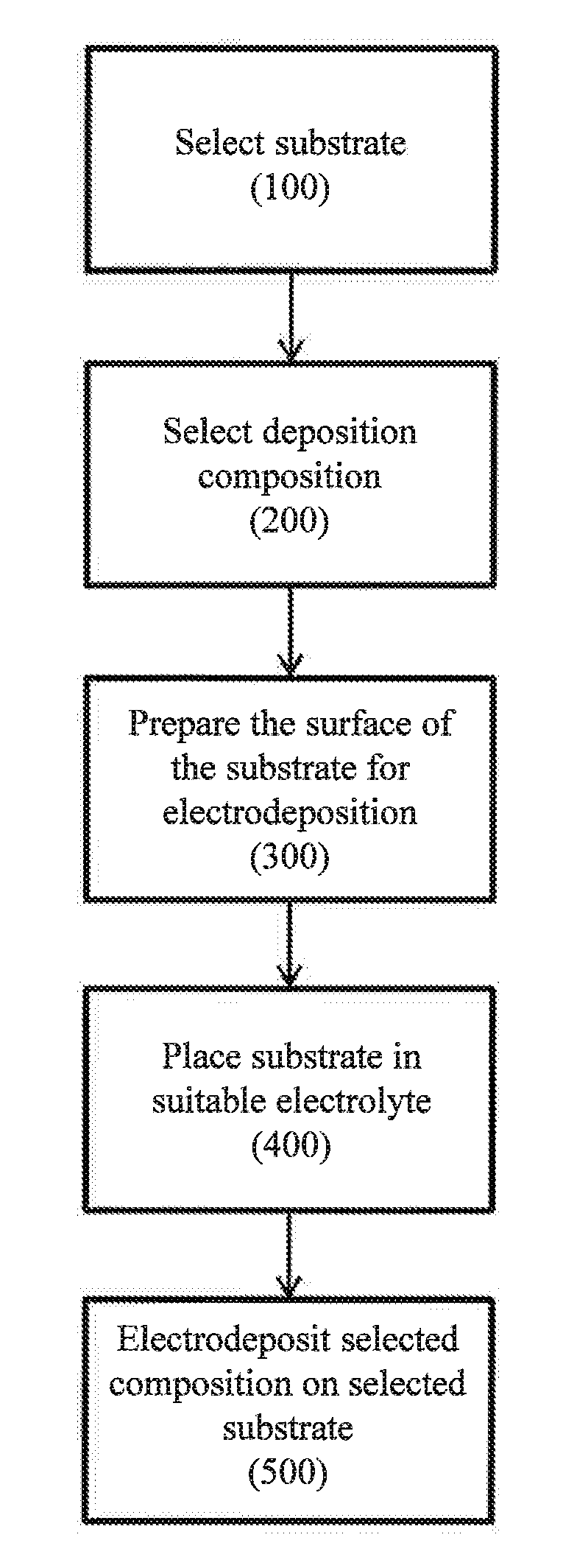
[0033] FIG. 1 is a flow chart illustrating one embodiment, of an electrodeposition method useful in accordance with the present disclosure.
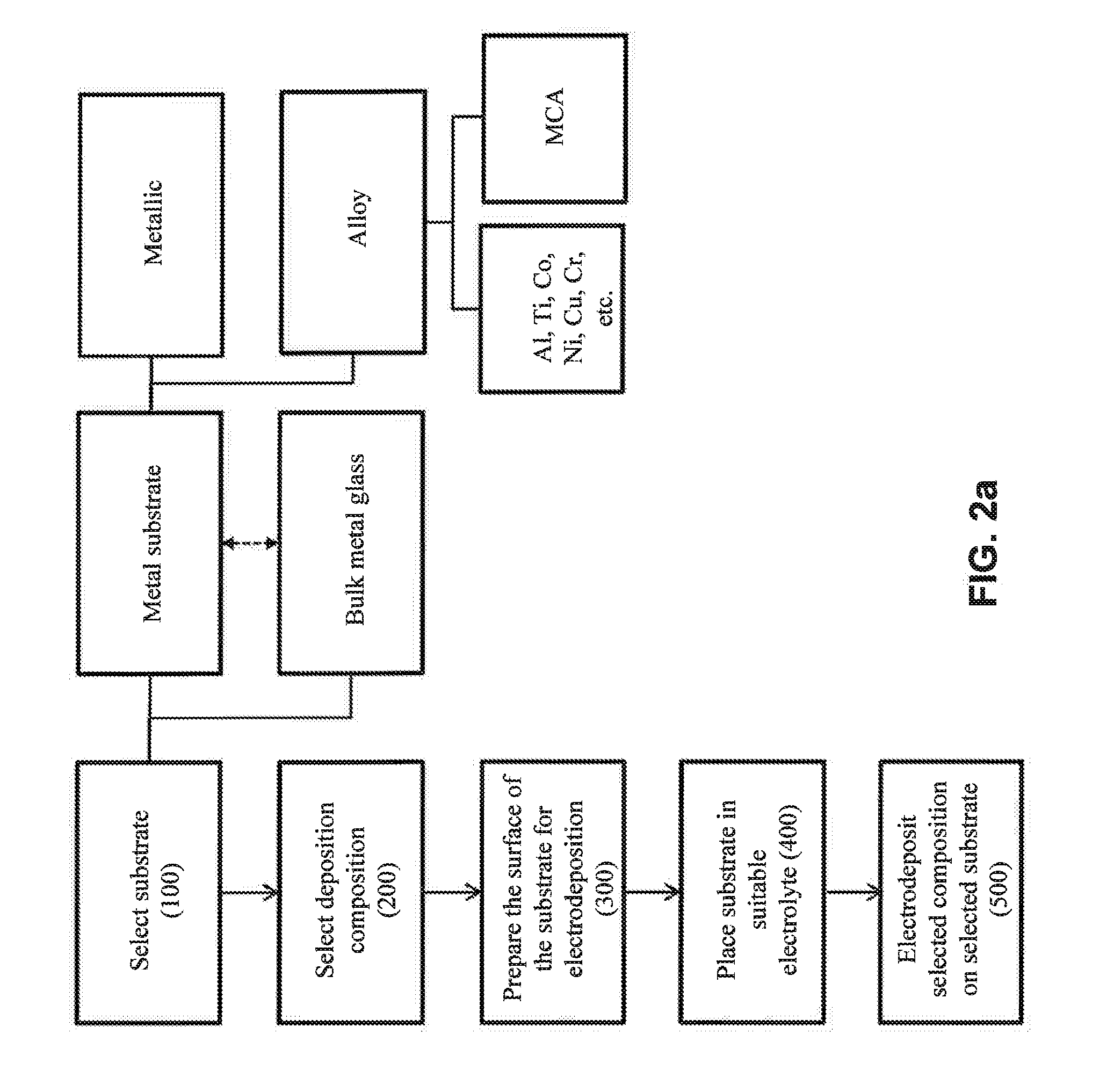
[0034] FIG. 2a illustrates various potential substrates for the selecting step (100) of FIG. 1.
[0035] FIG. 2b illustrates various potential materials for the deposition step (200) of FIG. 1.
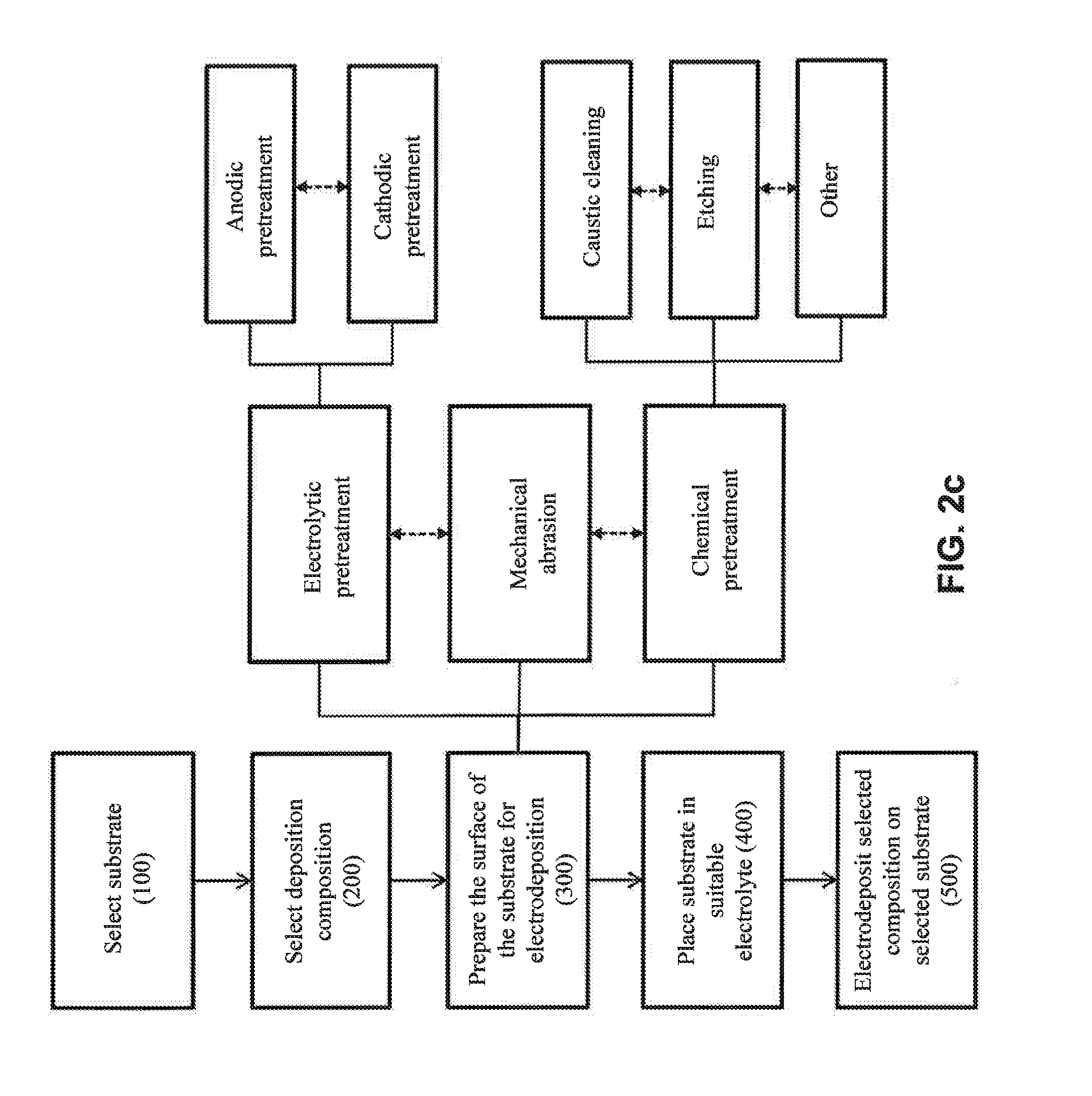
[0036] FIG. 2c illustrates various potential pretreatments for the preparing step (300) of FIG. 1.
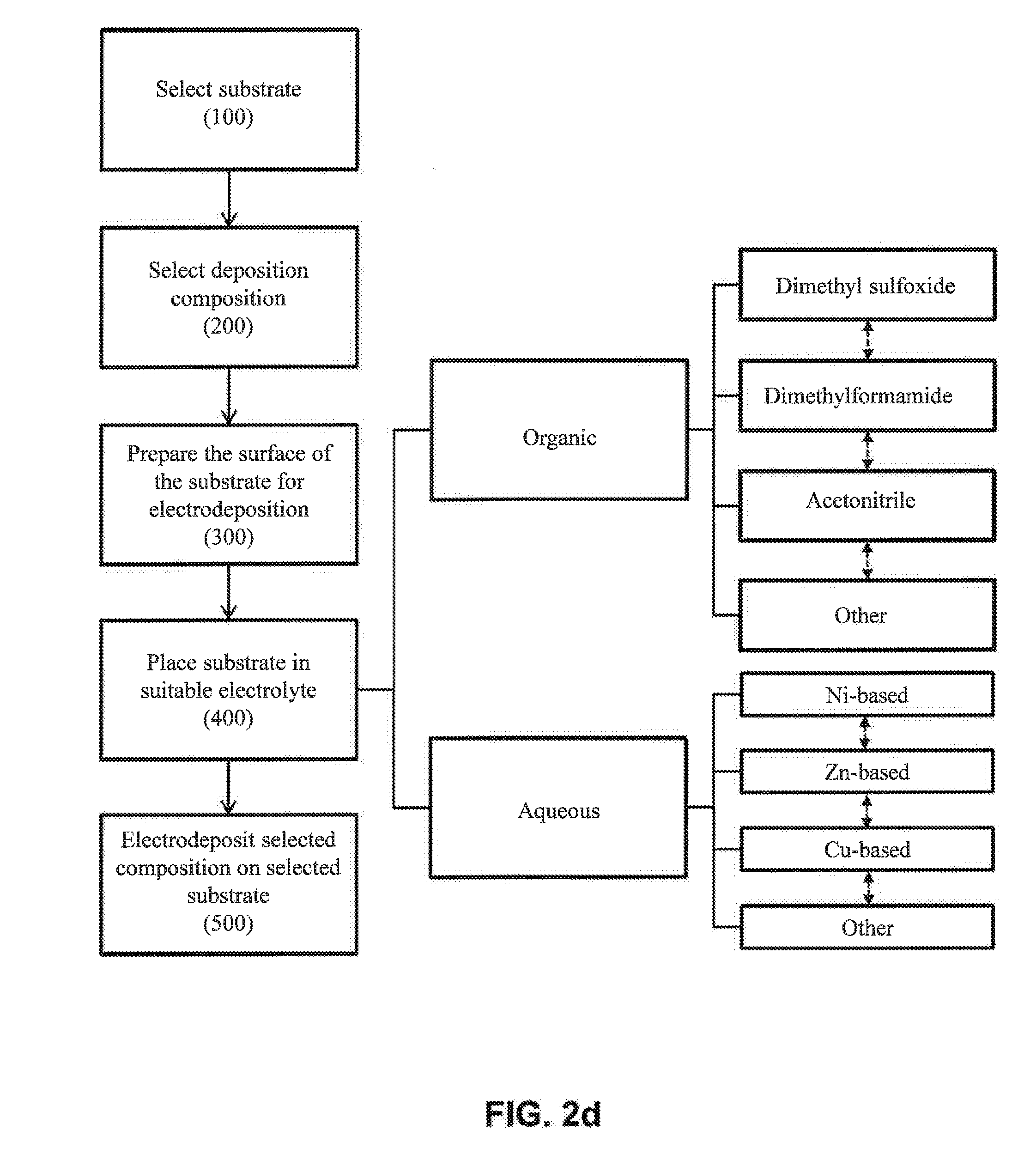
[0037] FIG. 2d illustrates various potential electrolytes for the placing step (400) of FIG. 1.
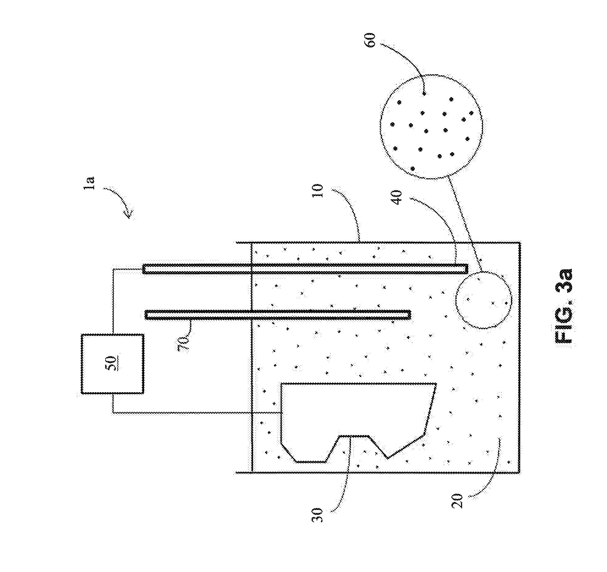
[0038] FIG. 3a is schematic side view of one embodiment of an electrodeposition system useful in accordance with the present disclosure.
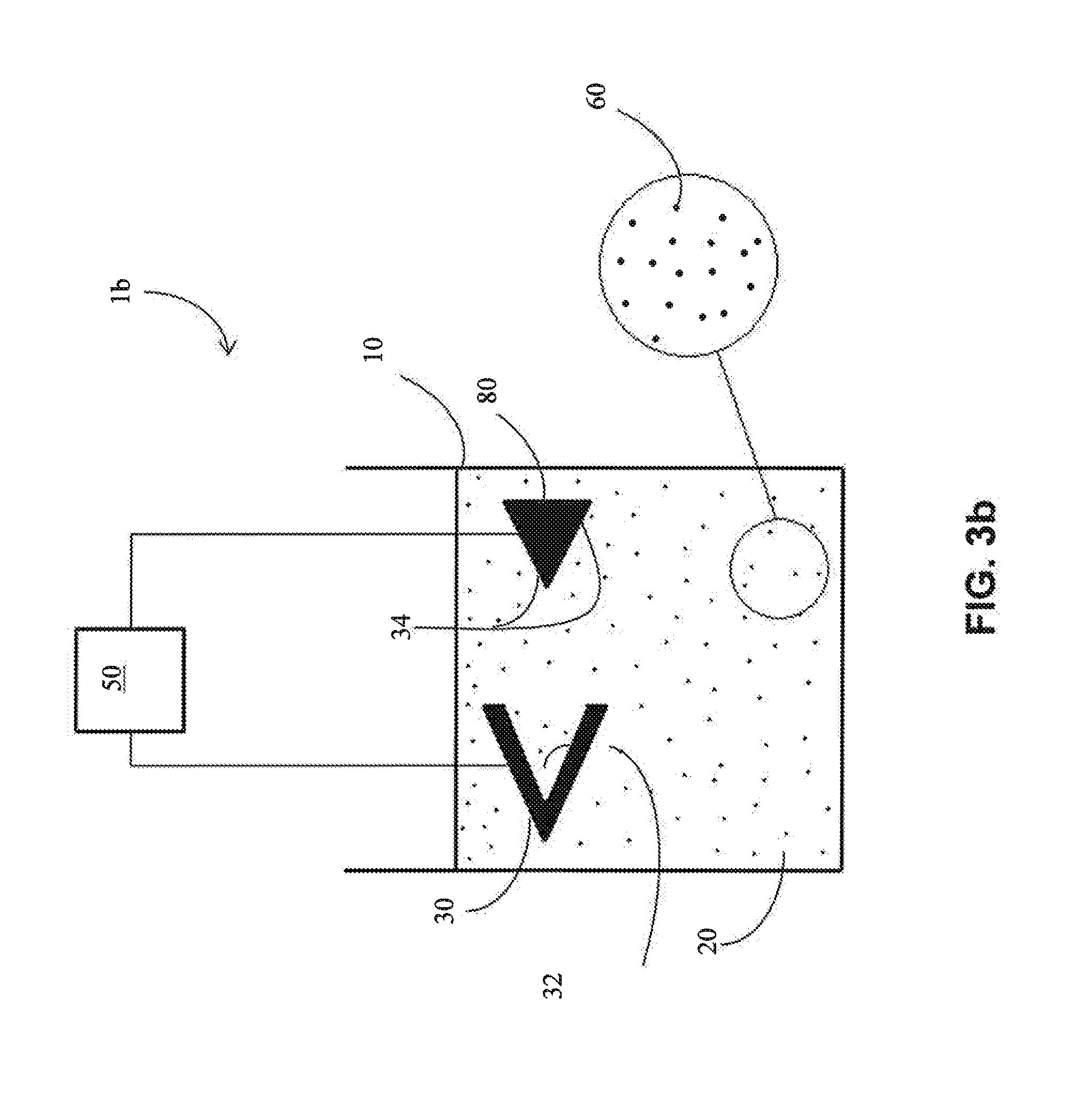
[0039] FIG. 3b is schematic side view of another embodiment of an electrodeposition system useful in accordance with the present disclosure.
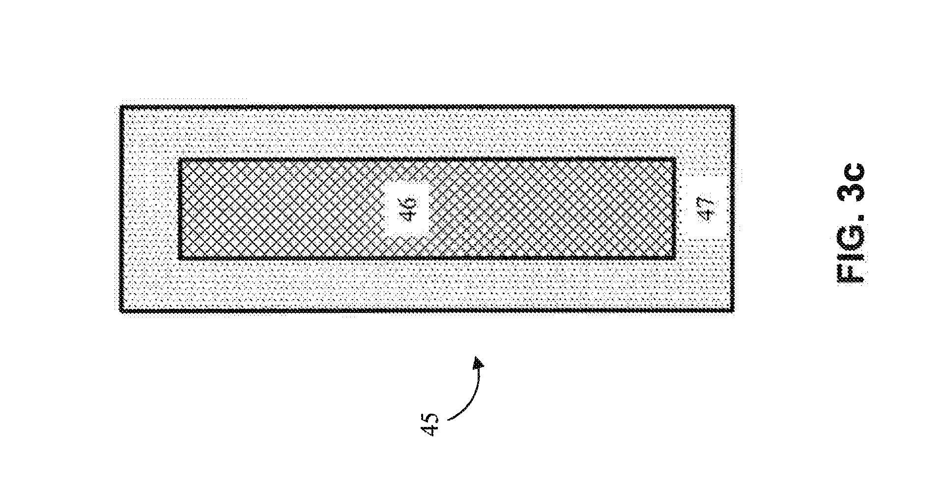
[0040] FIG. 3c is a cross-sectional view of an embodiment of a non-homogeneous anode that may be used in the electrodeposition systems disclosed herein.
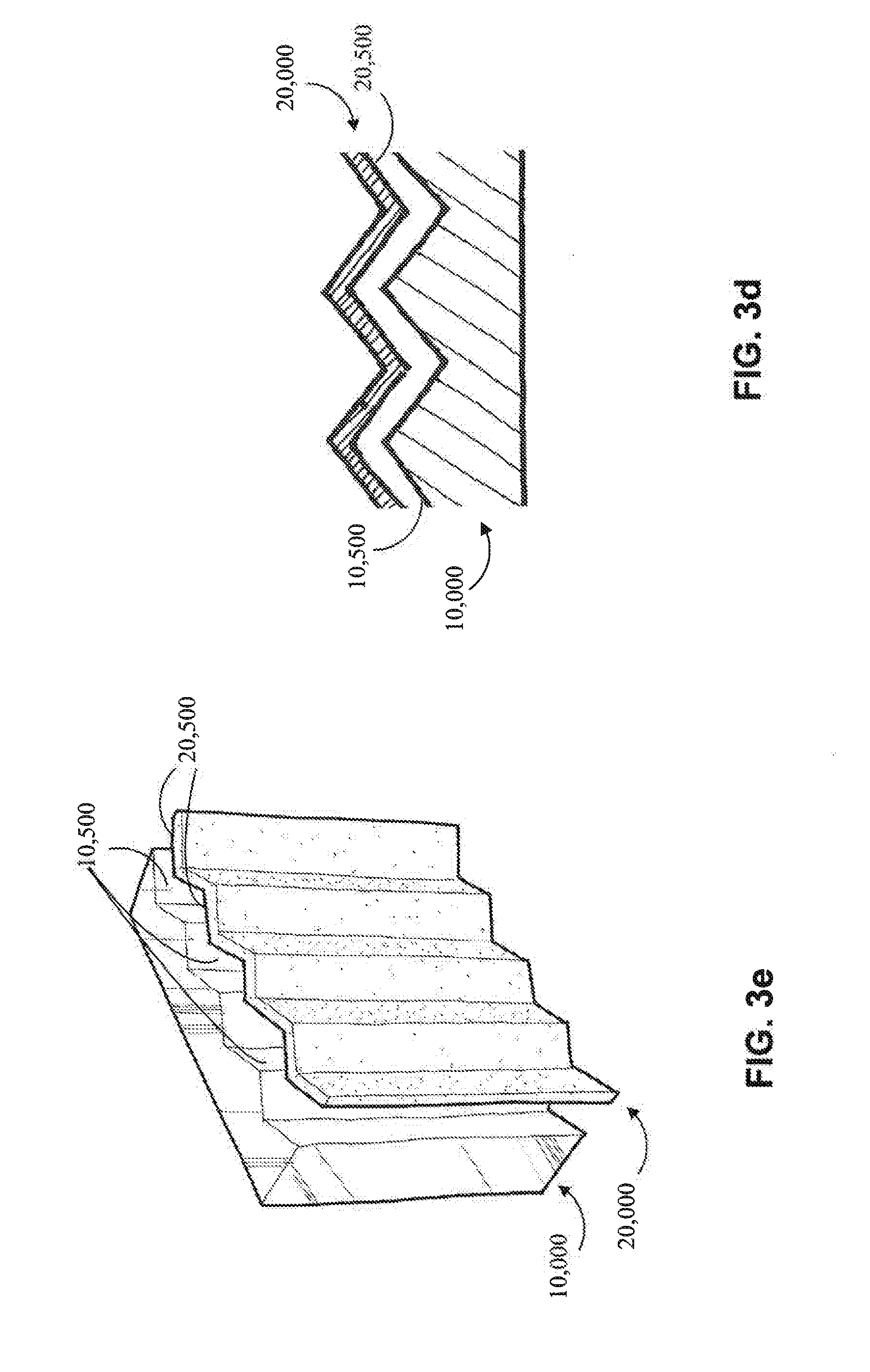
[0041] FIG. 3d is a perspective view illustrating one embodiment of a non-planar cathode and a corresponding non-planar anode.
[0042] FIG. 3e is a cross-sectional view of a portion of FIG. 3d.
[0043] FIG. 3f is a perspective view illustrating of one embodiment of a non-planar cathode and a corresponding non-planar anode.
[0044] FIG. 3g is a cross-sectional view of a portion of FIG. 3f.
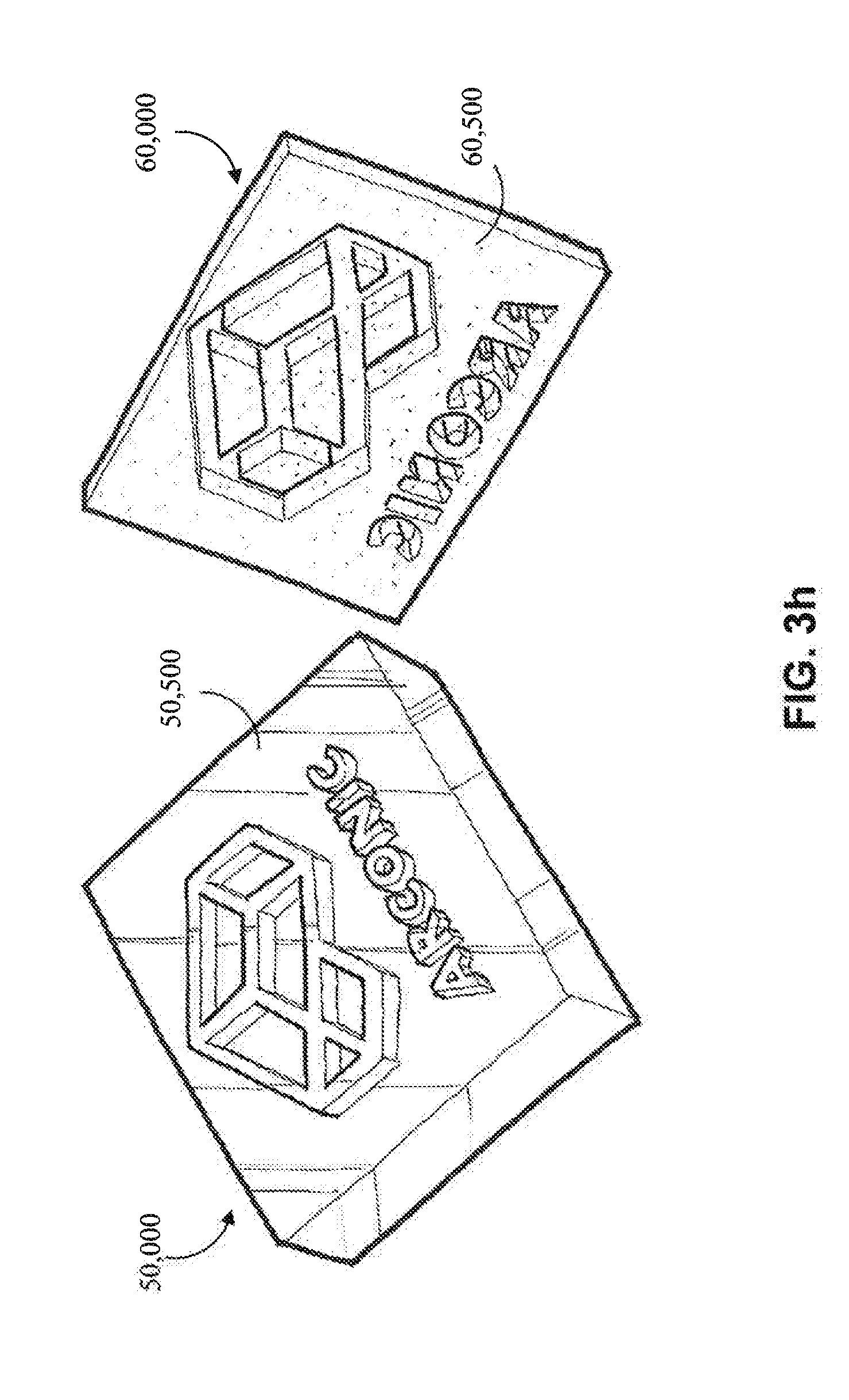
[0045] FIG. 3h is a perspective view illustrating one embodiment of a non-planar cathode and a corresponding non-planar anode.
[0046] FIG. 3i is a cross-sectional view of a portion of FIG. 3h.
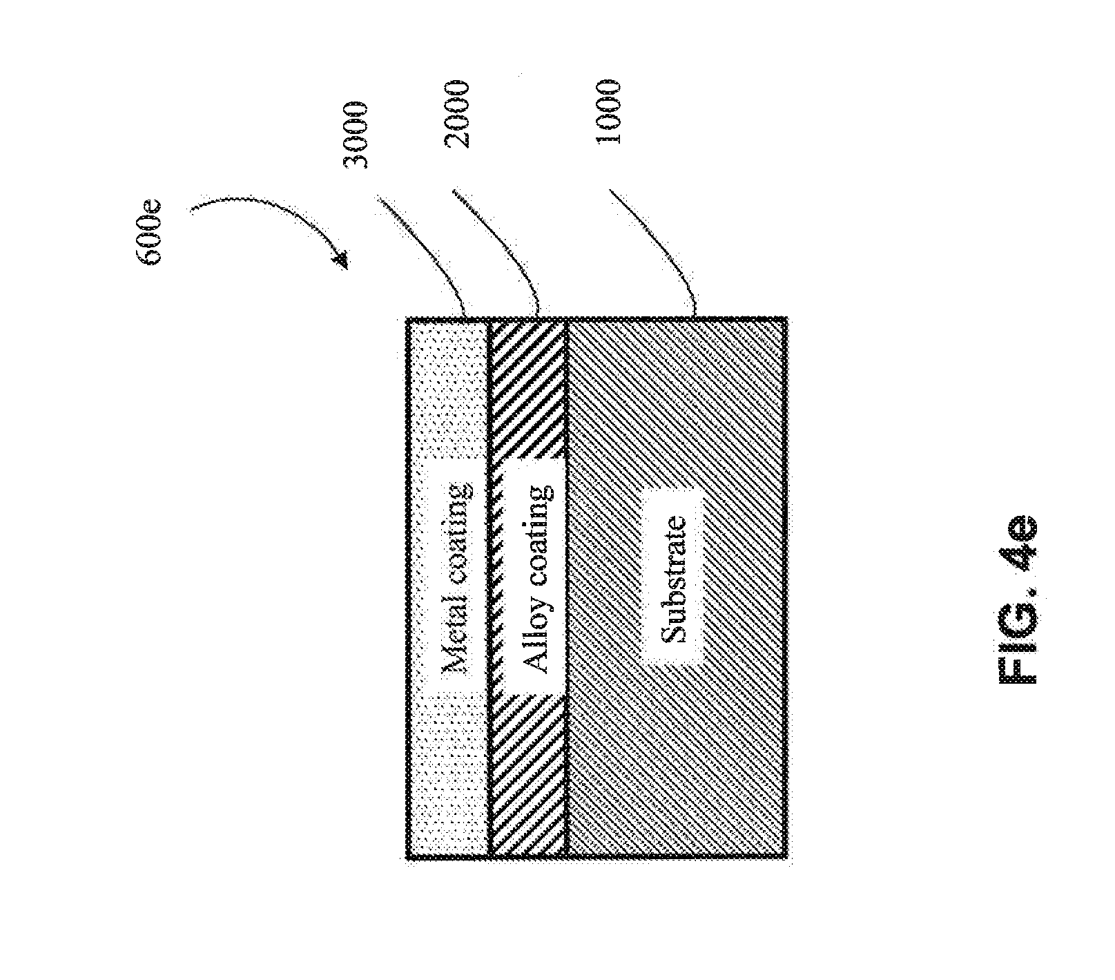
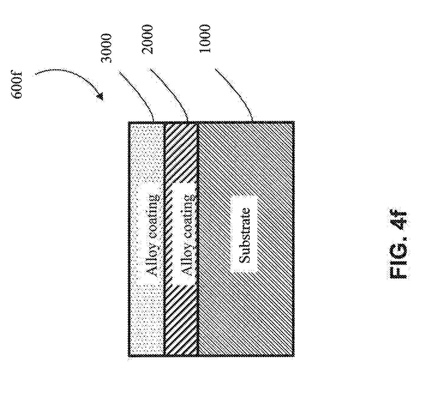
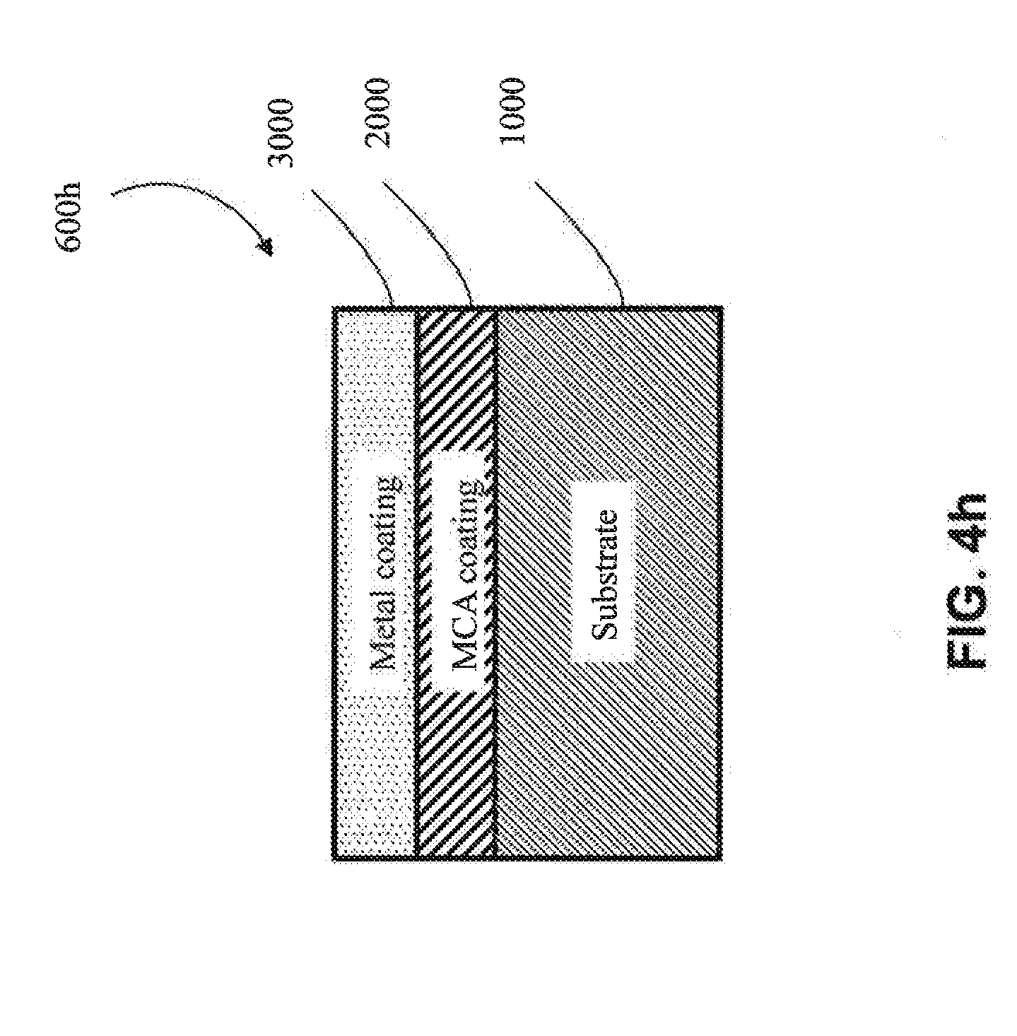
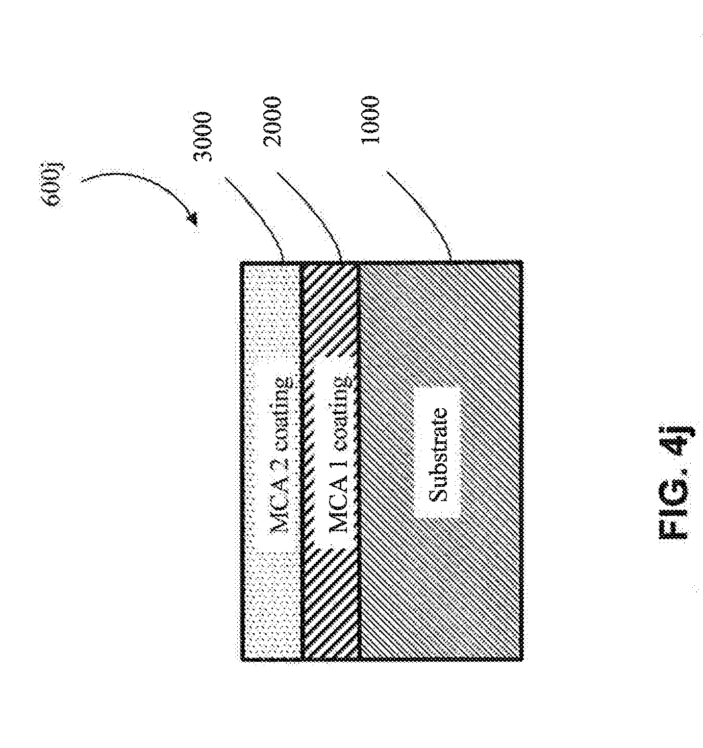
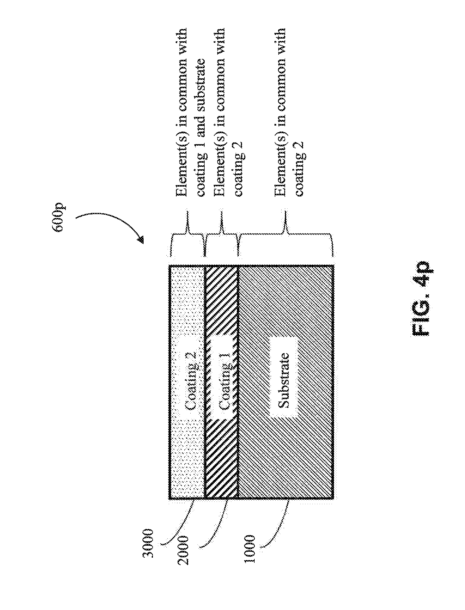
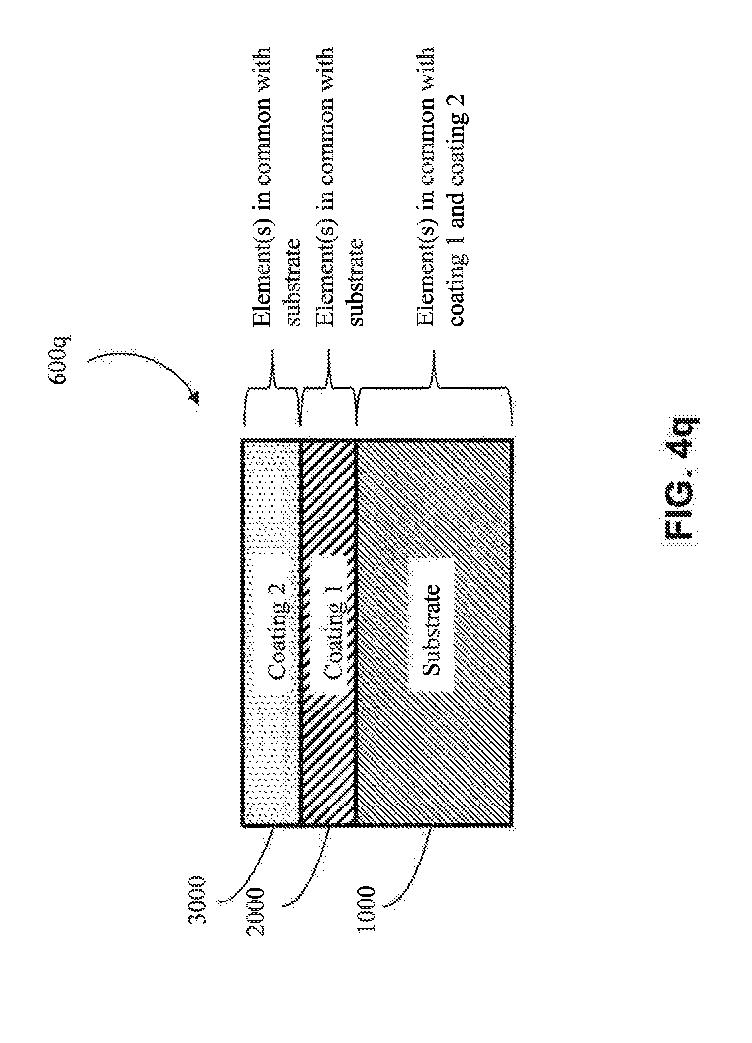
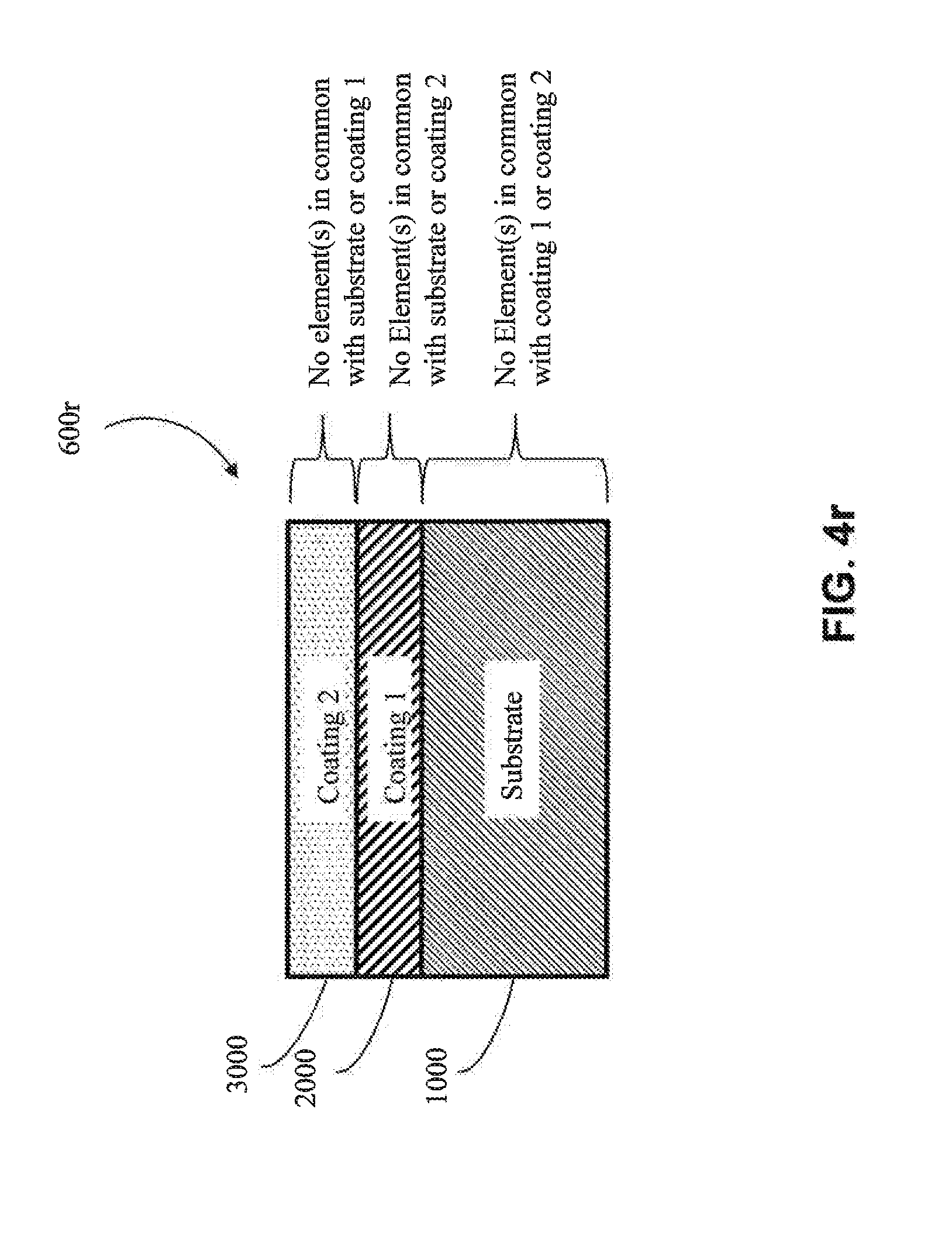
[0047] FIGS. 4a-4r illustrate various multi-layered products producible via the methods described in the present patent application.
DETAILED DESCRIPTION
[0048] Referring now to FIG. 1, one embodiment of a method for producing multi-layer products is illustrated. In the illustrated embodiment, the method includes the steps of selecting a substrate (100), selecting one or more deposition compositions to electrodeposit on the substrate (200), preparing the substrate, if needed, for deposition (300), placing the substrate in a suitable electrolyte bath (400), and electrodepositing the selected compositions on the selected substrate (500).
[0049] Referring now to FIG. 2a, various suitable substrates that may be selected for electrodeposition are shown. For instance, in one approach, the substrate is a metal substrate. In one embodiment, the metal substrate is a metallic substrate. In another embodiment, the metal substrate is a metal alloy. In one embodiment, the substrate is an Al metal alloy. In one embodiment, the substrate is a Ti metal alloy. In one embodiment, the substrate is a Co metal alloy. In one embodiment, the substrate is a Ni metal alloy. In one embodiment, the substrate is a Cu metal alloy. In one embodiment, the substrate is a Cr metal alloy. In one embodiment, the substrate is a multi-component alloy (MCA). In another approach, the substrate is a bulk metal glass substrate. In one embodiment, the solidus temperature of the substrate (e.g., a metal alloy substrate) is higher than that of any of the coatings thereon. In one embodiment, the glass transition temperature of the substrate (e.g., of a bulk metal glass substrate) is higher than that of any of the coatings thereon.
[0050] Referring now to FIG. 2b, various example deposition compositions suitable for electrodeposition are shown. In one embodiment, the deposition composition is a multi-component alloy (MCA). In one embodiment, the deposition composition is a metallic material. In another embodiment, the deposition composition is a metal alloy. In one embodiment, the deposition composition is an Al metal alloy. In one embodiment, the deposition composition is a Cr metal alloy. In one embodiment, the deposition composition is a Cu metal alloy. In one embodiment, the deposition composition is a Fe metal alloy. In one embodiment, the deposition composition is a Mn metal alloy. In one embodiment, the deposition composition is a Mg metal alloy. In one embodiment, the deposition composition is a Co metal alloy. In one embodiment, the deposition composition is a Ni metal alloy.
[0051] Referring now to FIG. 2c, optional substrate surface preparation steps are shown, which may be one or more of electrolytic pretreatment, mechanical abrasion and chemical pretreatment steps, among others. In one approach, the preparation step comprises an electrolytic pretreatment. In one embodiment, the electrolytic treatment comprises an anodic pretreatment (e.g., stripping surface(s) of the substrate). In one embodiment, the electrolytic pretreatment comprises a cathodic pretreatment (e.g., electrodeposition of a coating as a pretreatment). The electrolytic treatment may be a combination of anodic and cathodic treatments. In another approach, the pretreatment comprises mechanical abrasion. In another approach, the pretreatment comprises a chemical pretreatment. In one embodiment, the chemical pretreatment comprises caustic cleaning (e.g., using NaOH to remove oils or other contaminants from the surface of the substrate). In one embodiment, the chemical pretreatment comprises a deoxidizing process (e.g., etching the surface of the substrate to remove undesirable oxides, such as by an alkaline or acidic chemical treatment). The chemical pretreatment may be a combination of an etching step and a caustic cleaning step. The pretreatment may be any combination of the steps of an electrolytic pretreatment, mechanical abrasion and a chemical pretreatment.
[0052] Referring now to FIG. 2d, various electrolytic solvents useful for electrodeposition are shown. In one embodiment, the electrolyte solvent comprises one or more organic solvents (e.g., dimethyl sulfoxide, dimethylformamide and/or acetonitrile, among others). In another embodiment, the electrolyte solvent is an aqueous solvent. In one embodiment, the aqueous solvent comprises dissolved Zn-based salts. In one embodiment, the aqueous solvent comprises dissolved Ni-based salts. In one embodiment, the aqueous solvent comprises dissolved Cu-based salts. Other salts may be used.
[0053] Referring now to FIG. 3a, a system (1a) for electrodeposition is shown. In the illustrated embodiment, a container (10) comprises an electrolyte bath (20), a cathode in the form of an irregular substrate (30) and an anode (40). Cathode (30) and anode (40) are connected to current source (50) in electrical series. The electrolyte bath (20) includes metal ions (60). During the process of the electrodeposition, the metal ions (60) are deposited on surfaces of irregular cathode (30), thereby forming a coating (e.g., a uniform coating) thereon. An optional reference electrode (70) may be used to monitor potential of the electrolyte bath. The system (1a) of FIG. 3a may be used to electrodeposit a commercially viable coating (e.g., an adherent, uniform, continuous, and defect free coating).
[0054] In the embodiment, the anode (40) is consumable (e.g., dissolvable) and the metal ions (60) are formed in the electrolyte (20) by oxidation of the anode (40). When an electrical current is applied via current source (50), the consumable anode (40) begins to oxidize, and metal ions from the consumable anode are therefore present in the electrolyte bath (20) as a result of the oxidation of the anode. The electrochemical driving potential of the bath causes the metal ions to be deposited on the surfaces of the cathode (30) to form a coating thereon. In one embodiment, the deposited coating is homogeneous (e.g., when the anode is made of a pure metal or a suitable alloy). In another embodiment, the coating may be non-homogeneous (e.g., when the anode comprises alloys having sufficiently different electrochemical potentials). In one embodiment, a post-deposition thermal treatment may be used to provide a homogeneous coating as, described below.
[0055] In one embodiment, the anode (40) is homogeneous and comprises one of a metal, a metal alloy or an MCA to be deposited on the surface of the irregular substrate (30). In another embodiment, the anode (40) is non-homogeneous, (e.g., as per FIG. 3c, described below).
[0056] In one embodiment, the anode (40) comprises one or more MCAs to be deposited on the surface of the cathode (30). In one embodiment, the anode is homogeneous and comprises an MCA. In one embodiment, the anode is non-homogeneous and comprises an MCA.
[0057] In one embodiment, and referring now to FIG. 3c, a non-homogeneous anode (45) comprises an outer layer (47) and a core (46) disposed within the outer layer (47). The outer layer (47) comprises a first composition, and the core (46) comprises a second composition, different from the first composition. The non-homogeneous anode (45) of FIG. 3c may be used as an anode in any suitable electrodeposition system, including the systems of 1a and 1b of FIGS. 3a-3b, among others. During electrodeposition, the material of the outer layer (47) is deposited on the surface of the cathode (30). The deposition of material from the outer layer (47) onto the cathode (30) may continue until the outer layer (47) of the non-homogeneous anode (45) has been partially or completely oxidized. In the case where the outer layer (47) is fully utilized, the core (46) of the anode may be exposed, at which point the cathode (30) may be coated with the deposition composition of the core (46). In one embodiment, the outer layer (47) of the non-homogeneous anode (45) corresponds to the first deposited layer (2000) of any of the products of FIGS. 4a-4r. Accordingly, the core (46) of the non-homogeneous anode (45) may correspond to the second deposited layer (3000) of any of the products of FIGS. 4a-4r. Thus, the core (46) and outer layer (47) of the non-homogeneous anode (45) may be comprised of any materials described as suitable for the layers (2000) and (3000), relative to FIGS. 4a-4r, described below. Although the configuration of FIG. 3c shows a single layer around a cylindrical core, it will be appreciated that the non-homogeneous anode (45) may comprise multiple layers (47 l-n) around a core (46) to facilitate electrodeposition of multiple different layers on the cathode.
[0058] In another approach, the anode is non-consumable or marginally dissolvable in the electrolyte. In this approach, metal salts may be fed to the electrolyte bath (20) to provide metal ions in solution. The one or more metal salts dissolve in the electrolyte bath (20) providing the metal ions (60) necessary to electrodeposit a coating on the surface of the irregular substrate (30). The deposition composition may be altered by selecting the appropriate one or more metal salts to provide the appropriate concentration of metal ions. In one embodiment, the electrolyte bath (20) comprises a single metal salt in order to allow for the deposition of a single metal coating (e.g., AlCl.sub.3 to deposit aluminum). In another embodiment, a blend of metal salts comprises several metal salts that, when dissolved in the electrolyte solvent, will allow for the correct concentration of metal ions to electrodeposit a desired metal alloy. In one embodiment, a blend of metal salts comprises several metal salts that, when dissolved in the electrolyte solvent, will allow for the correct concentration of metal ions to electrodeposit a desired MCA.
[0059] FIG. 3b illustrates a variation of FIG. 3a where an anode (80) of the system 1b comprises a predetermined volume and opposing exterior surface (34) that corresponds to a non-planar exterior surface (32) of the cathode (irregular substrate) (30). Such an arrangement may facilitate a generally uniform current density during the electrodeposition process. Due to the arrangement/configuration of the opposing exterior surface (34) of the anode (80) and the non-planar exterior surface (32) of the cathode (30), a coating may be uniformly deposited on the surface of the cathode (30). In some embodiments, the current source (50) utilizes a generally constant current, which may be facilitated by the use of a non-planar anode (80) with a predetermined opposing exterior surface (34) that corresponds to the non-planar exterior surface (32) of the cathode (30). The anode (80) and or cathode (30) may be additively manufactured, stamped, forged, or shape cast, among others, to facilitate production of complex shapes for these electrodes. In one embodiment, one or both of the cathode and anode used in the electrodeposition process may be produced via additive manufacturing. In one embodiment, the anode is additively manufactured, and may be homogeneous or non-homogeneous, as described above. Similarly, a cathode may be homogeneous or non-homogeneous. In one embodiment, the cathode and the anode are both additively manufactured. In another embodiment, only one of the cathode and anode are additively manufactured. In one embodiment, at least one of the electrodes is produced using additive manufacturing, wherein the at least one corresponding electrode is produced using a 3-dimensional image produced via 3-dimensional imaging techniques. For instance, a cathode (32) may be scanned using 3-dimensional imaging techniques, and at least one corresponding 3-dimensional image used to additively manufacture at least one anode (80). The corresponding anode(s) (80) may have a pre-determined volume and opposing exterior surface (34) that may facilitate a generally uniform current density during the electrodeposition process. In this regard, the 3-dimensional imaging technique may include using one or more digital cameras, where the one or more of digital cameras may produce one or more digital images. Such one or more digital images may be utilized by computer software to construct one or more 3-dimensional images of the corresponding electrode(s) to be fabricated. For instance, the computer software may be configured to utilize one or more digital images to produce one or more electrodes generally having a structure that mirrors that of the corresponding electrode. The computer may use electrodeposition modeling software to optimize the current density of the electrodeposition process. For instance, the current density of the electrodeposition process may be modeled using by constructing a 3-dimensional model of the electrode(s) to be utilized in the electrodeposition process.
[0060] Referring now to FIGS. 3a and 3d-3e, another example of a non-planar anode (20,000) and a non-planar cathode (10,000) is shown. The cathode (10,000) comprises a non-planar exterior surface (10,500) and the anode (20,000) comprises a corresponding predetermined opposing exterior surface (20,500), generally matching the shape of the cathode's exterior surface (10,500). In some embodiments, the current source (50) utilizes a generally constant current, which may be facilitated by the use of a non-planar anode (20,000) with a predetermined opposing exterior surface (20,500) that corresponds to the non-planar exterior surface (10,500) of the cathode (10,000).
[0061] Referring now to FIGS. 3a, and 3f-3g, another embodiment of a non-planar anode (40,000) and a corresponding non-planar cathode (30,000) is shown. The cathode (30,000) comprises a non-planar exterior surface (30,500) and the anode (40,000) comprises a corresponding predetermined opposing exterior surface (40,500). The non-planar exterior surface (30,500) of the cathode (30,000) is comprised of a first portion (30,600), a second portion (30,700), and a third portion (30,800). The third portion (30,800) is connected to the first portion (30,600) via the second portion (30,700). The predetermined opposing exterior surface (40,500) of the anode (40,000) comprises a first portion (40,600), a second portion (40,700), and a third portion (40,800). The third portion (40,800) is connected to the first portion (40,600) via the second portion (40,700). The first portion (30,600) of the non-planar exterior surface (30,500) of the cathode (30,000) corresponds to the size and shape of the first portion (40,600) of the predetermined opposing exterior surface (40,500) of the anode (40,000). The second portion (30,700) of the non-planar exterior surface (30,500) of the cathode (30,000) corresponds to the size and shape of the second portion (40,700) of the predetermined opposing exterior surface (40,500) of the anode (40,000). The third portion (30,800) of the non-planar exterior surface (30,500) of the cathode (30,000) corresponds to the size and shape of the third portion (40,800) of the predetermined opposing exterior surface (40,500) of the anode (40,000). As illustrated, the remainder of the anode (40,000) corresponds to the remainder of the cathode (30,000). In some embodiments, the current source (50) utilizes a generally constant current, which may be facilitated by the use of a non-planar anode (40,000) with a predetermined opposing exterior surface (40,500) that corresponds to the non-planar exterior surface (30,500) of the cathode (30,000). The generally constant current may facilitate a uniform coating.
[0062] Referring now to FIGS. 3a and 3h-3i, another embodiment of a combination of a non-planar cathode (50,000) and a non-planar anode (60,000) is shown. The cathode (50,000) comprises a non-planar exterior surface (50,500) and the anode (60,000) comprises the predetermined opposing exterior surface (60,500). In some embodiments, the current source (50) utilizes a generally constant current, which may be facilitated by the use of a non-planar anode (60,000) with a predetermined opposing exterior surface (60,500) that corresponds to the non-planar exterior surface (50,500) of the cathode (50,000). The generally constant current may facilitate a uniform coating.
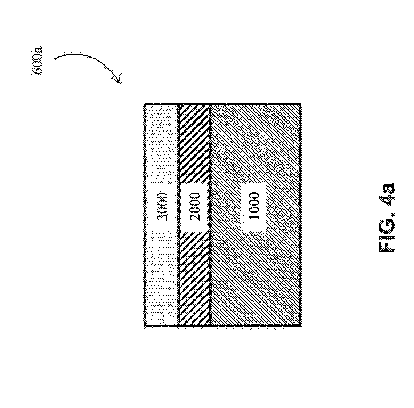
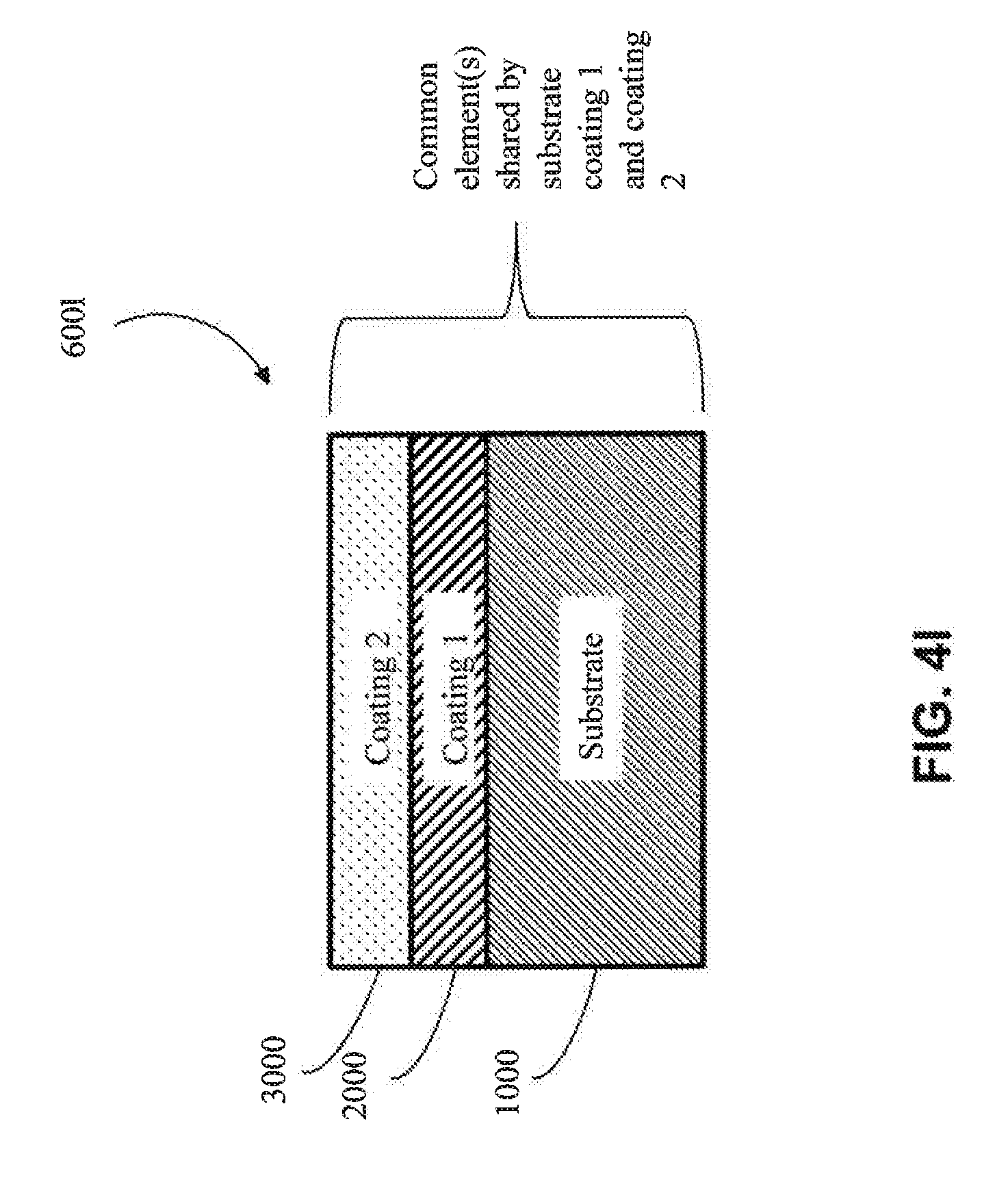
[0063] Referring now to FIG. 4a, a schematic cross-sectional view of an embodiment of a multilayered product (600a) is shown. The illustrated multi-layered product (600a) comprises a substrate (1000), a first coating (2000) and an optional second coating (3000). Other layers may be used. In one embodiment, the first coating (2000) is a final or a capping layer. In another embodiment, the first coating (2000) is an intermediate layer, and accordingly, the second coating (3000) is a final or capping layer. In another embodiment, the second layer (3000) is an intermediate layer.
[0064] The substrate (1000) may be any suitable substrate useful as a cathode in an electrodeposition bath, including any of the substrates described above. In one approach, the substrate (1000) is a metal substrate. In one embodiment, the metal substrate is a metallic substrate. In one embodiment, the metal substrate is a metal alloy substrate (e.g., one of Al, Ti, Co, Ni, Cu and Cr metal alloys, among others). In one embodiment, the metal substrate (1000) is a multi-component alloy substrate. In another embodiment, the substrate (1000) is a bulk metal glass substrate.
[0065] The first coating (2000) may be any suitable coating producible via electrodeposition, spray deposition and/or additive manufacturing, including any of the coatings described above. In one embodiment, the first coating (2000) is electrodeposited. In another embodiment, the first coating (2000) is produced by additive manufacturing. In another embodiment, the first coating (2000) is produced by spray deposition.
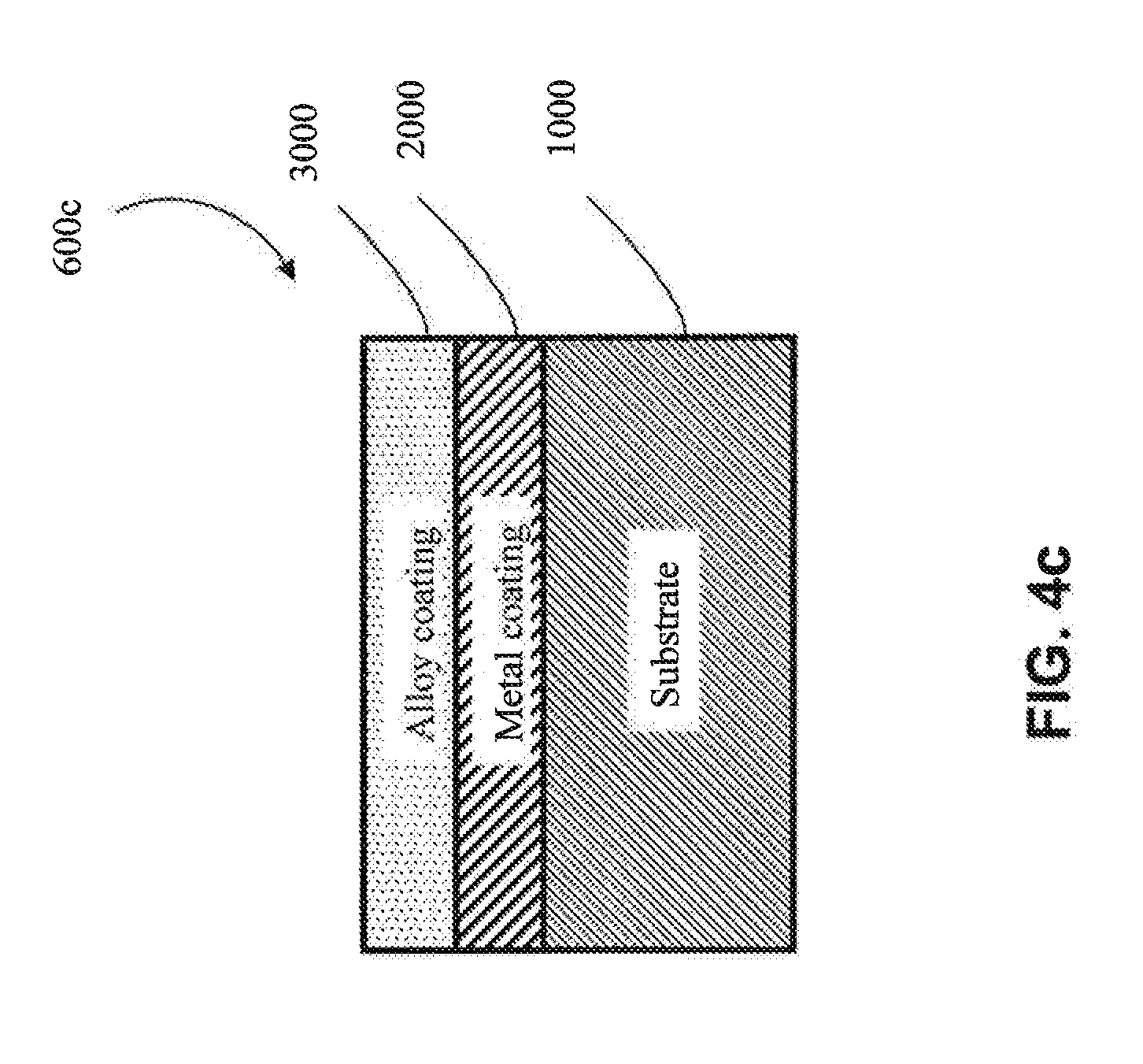
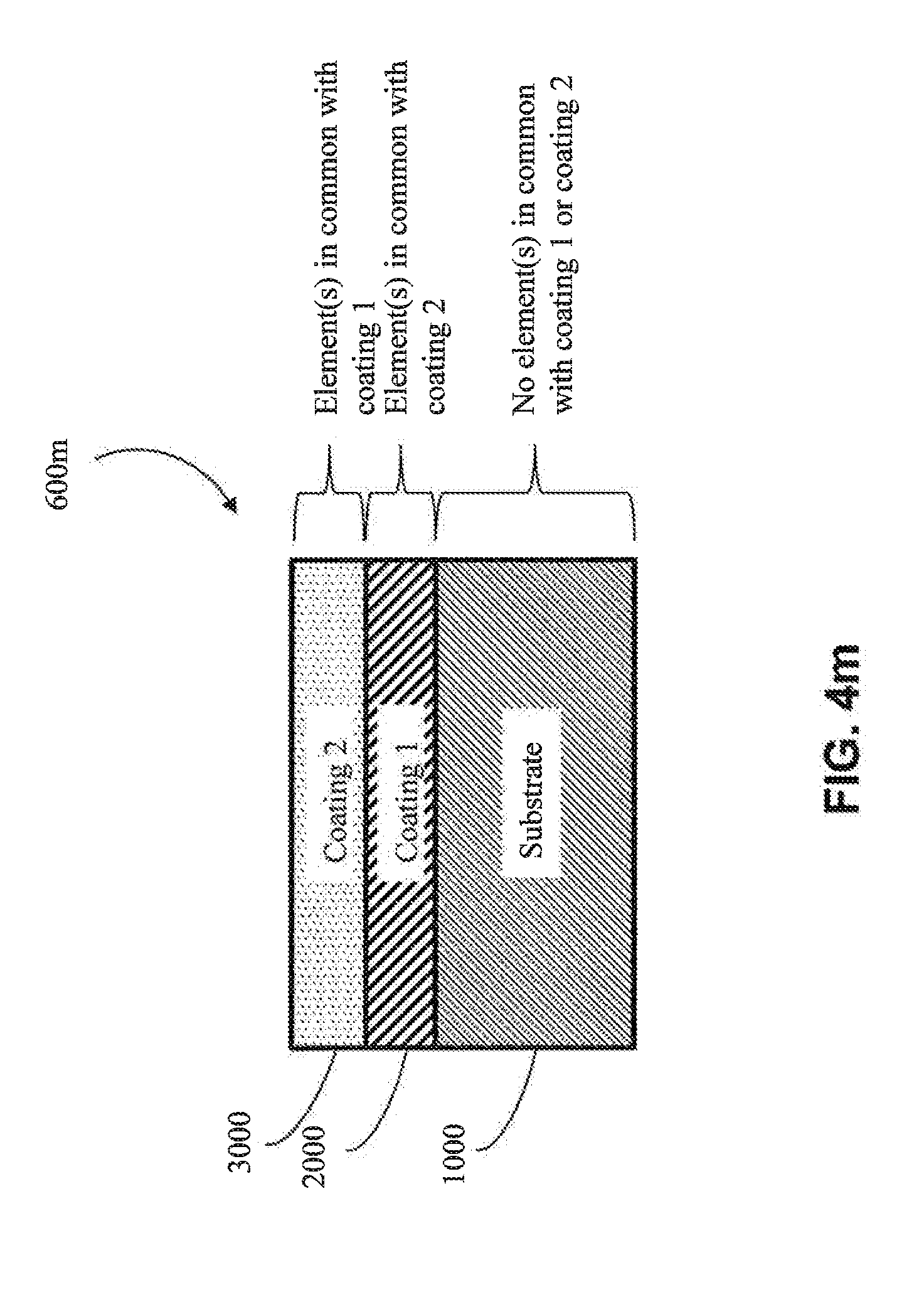
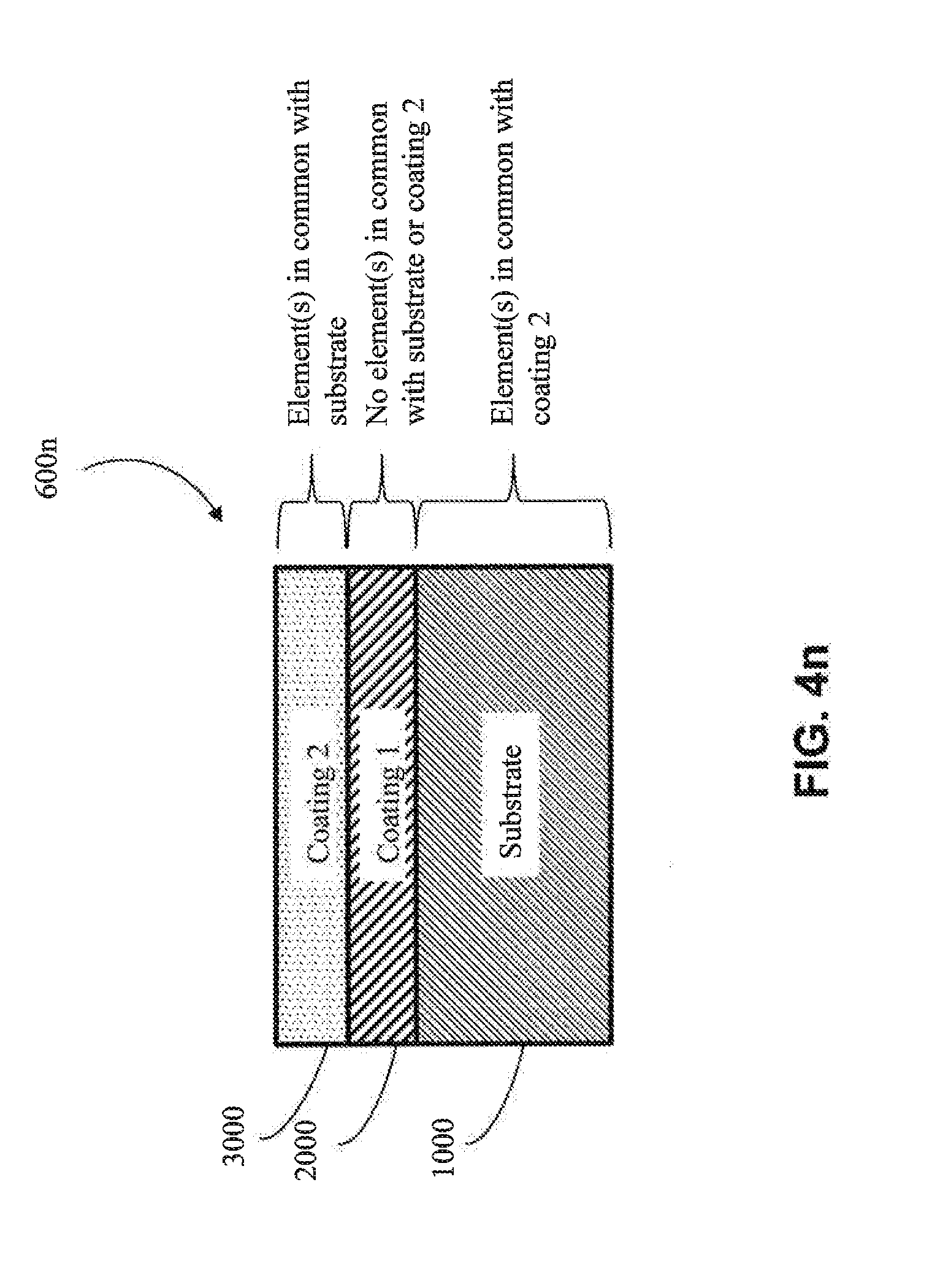
[0066] In one approach, the first coating (2000) is metallic, as shown in FIG. 4b-4d (e.g., is metallic aluminum). In one embodiment, the metal of the first coating (2000) has one or more elements in common with the substrate (1000) (e.g., in FIGS. 4k, 4l, 4o and 4q) (e.g., the substrate and the first coating both comprise aluminum). In one embodiment, the metal of the first coating (2000) does not have any elements in common with the substrate (1000) (e.g., as shown in 4m, 4n, 4p and 4r) (e.g., if the substrate (1000) is aluminum, then the metal of the first coating (2000) would not contain aluminum, except as an impurity).
[0067] In another approach, the first coating (2000) is a metal alloy (e.g, as shown in FIG. 4e-FIG. 4g) (e.g., a metal alloy of Al, Cr, Cu, Fe, Mn, Co or Ni, among other metal alloys). In one embodiment, the metal alloy is a metal alloy of Al. In one embodiment, the metal alloy is a metal alloy of Cr. In one embodiment, the metal alloy is a metal alloy of Cu. In one embodiment, the metal alloy is a metal alloy of Fe. In one embodiment, the metal alloy is a metal alloy of Mn. In one embodiment, the metal alloy is a metal alloy of Co. In one embodiment, the metal alloy is a metal alloy of Ni. In one embodiment, the metal alloy of the first coating (2000) has one or more elements in common with the substrate (1000) (e.g., as shown in FIGS. 4k, 4l, 4o and 4q) (e.g., if the substrate (1000) comprises aluminum, the first coating (2000) comprises aluminum). In one embodiment, the metal alloy of the first coating (2000) has no elements in common with the substrate (1000) (e.g., as shown in FIGS. 4m, 4n, 4p and 4r) (e.g., if the substrate (1000) is aluminum, then the metal alloy of the first coating (2000) would not contain aluminum, except as an impurity).
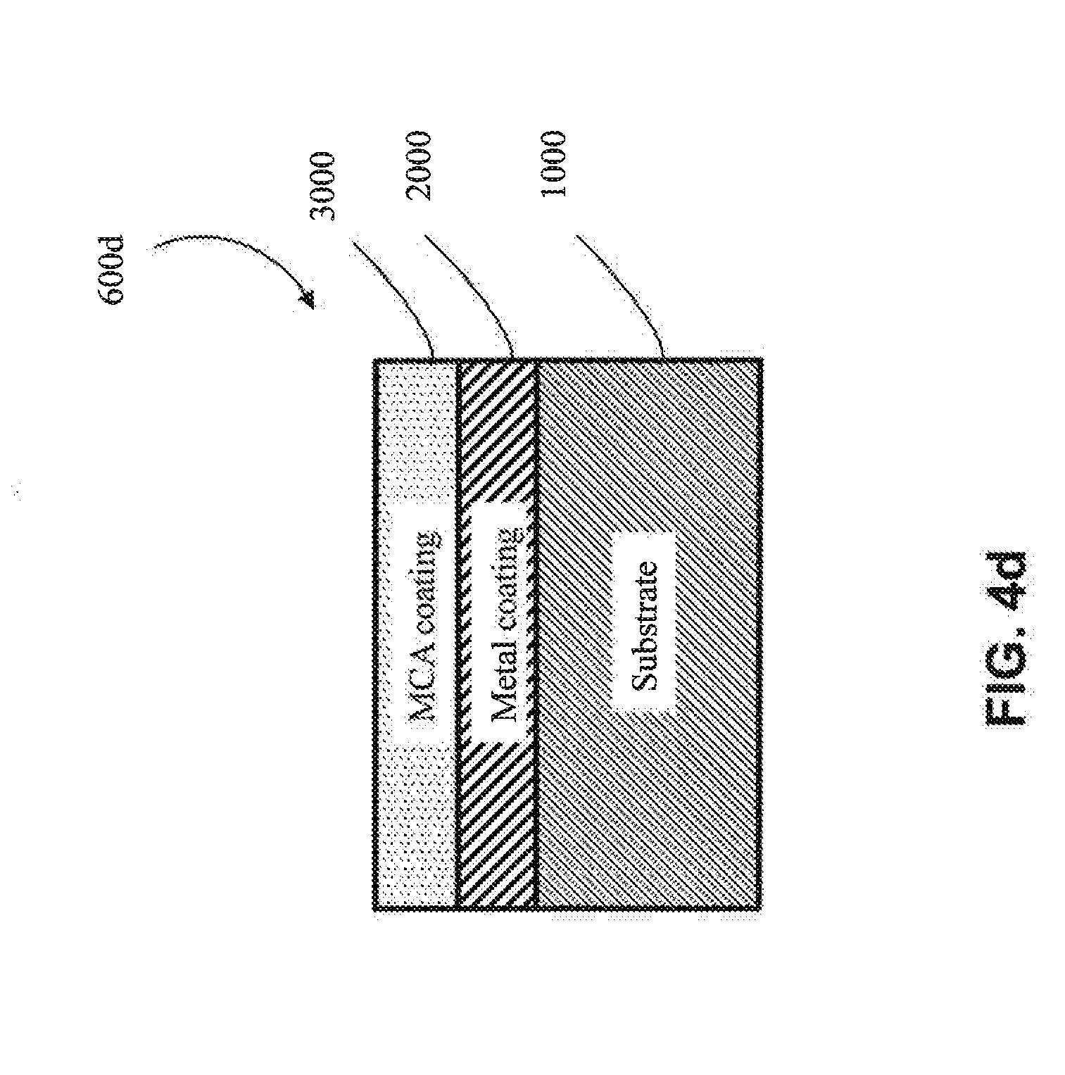
[0068] In one particular approach, the first coating (2000) is an MCA (e.g., as shown in FIGS. 4h-4j). In one embodiment, the MCA of the first coating (2000) does not share any common elements with the substrate (1000) (e.g., as shown in FIGS. 4m, 4n, 4p and 4r) (e.g., if the substrate (1000) includes aluminum, the MCA of the first coating (2000) would not contain aluminum, except as an impurity). In one embodiment, the MCA of the first coating (2000) shares one or more common elements with the substrate (1000) (e.g., as shown in FIGS. 4k, 4l, 4o and 4q) (e.g., if the substrate (1000) includes aluminum, then the MCA of the first coating would also comprise aluminum as one of its at least four elements). In one embodiment, the MCA of the first coating (2000) shares at least two common elements with the substrate (1000) (e.g., both the substrate (1000) and the first coating (2000) comprise aluminum and copper). In one embodiment, the MCA of the first coating (2000) shares at least three common elements with the substrate (1000) (e.g., both the substrate (1000) and the first coating (2000) comprise aluminum, copper and nickel).
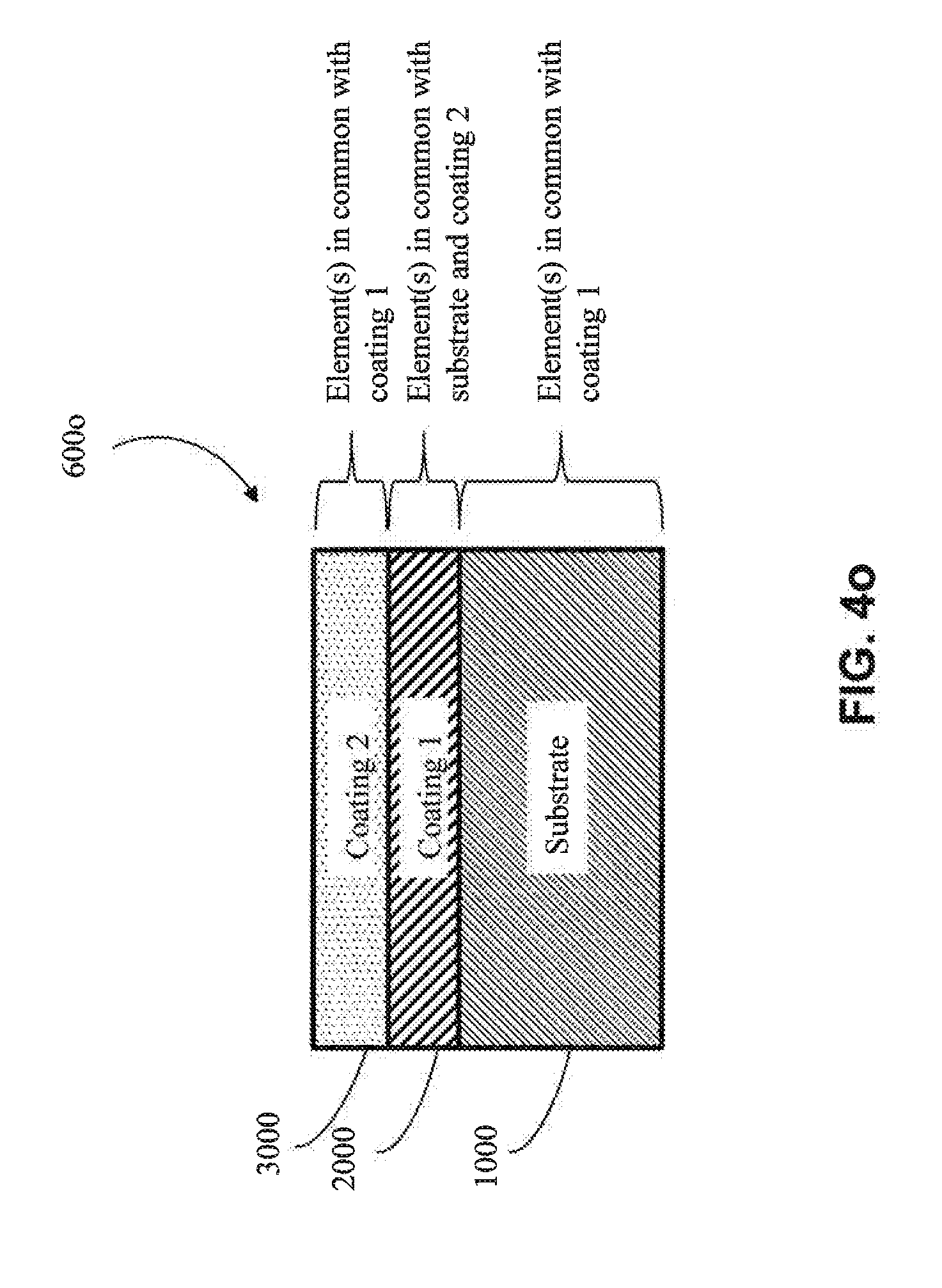
[0069] In one embodiment, the first coating (2000) shares one or more elements in common with the optional second coating (3000) (e.g., as shown in FIGS. 4l, 4m, 4o, and 4p) (e.g., the first coating (2000) and the second coating (3000) both comprise aluminum). In another embodiment, the first coating (2000) shares no elements in common with an optional second coating (3000) (e.g., as shown in FIGS. 4k, 4n, 4q, 4r) (e.g., if the first coating (2000) comprises copper, then the second coating (3000) would not contain copper except as an impurity). In one embodiment, the first coating (2000) shares one or more common elements with both the substrate (1000) and the optional second coating (3000) (e.g., as shown in FIGS. 4l and 4o) (e.g., the substrate (1000), the first coating (2000) and the second coating (3000) all comprise aluminum).
[0070] The second coating (3000) may be any suitable coating producible via electrodeposition, spray deposition, and/or additive manufacturing, including any of the coatings described above. In one embodiment, the second coating (3000) is electrodeposited. In another embodiment, the second coating (3000) is produced by additive manufacturing. In another embodiment, the second coating (3000) is produced by spray deposition.
[0071] In one approach, the second coating (3000) is metallic (e.g., metallic aluminum). In one embodiment, the metal of the second coating (3000) has one or more elements in common with the substrate (1000) (e.g., as shown in FIGS. 4l, 4n, 4p, and 4q) (e.g., the substrate (1000) and the second coating (3000) both comprise aluminum). In one embodiment, the metal of the second coating (3000) does not have any elements in common with the substrate (1000) (e.g., as shown in FIGS. 4k, 4m, 4o, and 4r) (e.g., if the substrate (1000) were aluminum, the metal of the second coating (3000) would not contain aluminum, except as an impurity). In one embodiment, the metal of the second coating (3000) has one or more elements in common with the first coating (2000) (e.g., as shown in FIGS. 4l, 4m, 4o, and 4p) (e.g., the first coating (2000) and the second coating (3000) both comprise copper). In one embodiment, the metal of the second coating (3000) does not have any elements in common with the first coating (2000) (e.g., as shown in FIGS. 4k, 4n, 4q and 4r) (e.g., if the first coating (2000) were copper, the metal of the second coating (3000) would not contain copper except as an impurity).
[0072] In another approach, the second coating (3000) is a metal alloy coating (e.g., a metal alloy of Al, Cr, Cu, Fe, Mn, Co or Ni, among other metal alloys). In one embodiment, the metal alloy is a metal alloy of Al. In one embodiment, the metal alloy is a metal alloy of Cr. In one embodiment, the metal alloy is a metal alloy of Cu. In one embodiment, the metal alloy is a metal alloy of Fe. In one embodiment, the metal alloy is a metal alloy of Mn. In one embodiment, the metal alloy is a metal alloy of Co. In one embodiment, the metal alloy is a metal alloy of Ni. In one embodiment, the metal alloy of the second coating (3000) has one or more elements in common with the substrate (1000) (e.g., as shown in FIGS. 4l, 4n, 4p, and 4q) (e.g., the substrate (1000) and the second coating (3000) both comprise aluminum). In one embodiment, the metal alloy of the second coating (3000) has no elements in common with the substrate (1000) (e.g., as shown in FIGS. 4k, 4m, 4o, and 4r) (e.g., if the substrate (1000) were aluminum, the metal alloy of the second coating (3000) would not contain aluminum, except as an impurity). In one embodiment, the metal alloy of the second coating (3000) has one or more elements in common with the first coating (2000) (e.g., as shown in FIGS. 4l, 4m, 4o, and 4p) (e.g., the first coating (2000) and the second coating (3000) both comprise copper). In one embodiment, the metal alloy of the second coating (3000) does not have any elements in common with the first coating (2000) (e.g., as shown in FIGS. 4k, 4n, 4q and 4r) (e.g., if the first coating (2000) were copper, the metal alloy of the second coating (3000) would not contain copper except as an impurity).
[0073] In one particular approach, the second coating (3000) is an MCA coating. In one embodiment, the MCA of the second coating (3000) does not share any common elements with the substrate (1000) (e.g., as shown in FIGS. 4k, 4m, 4o, and 4r) (e.g., if the substrate (1000) were aluminum, the second coating (3000) would not contain aluminum, except as an impurity). In one embodiment, the MCA of the second coating (3000) shares one or more common elements with the substrate (1000) (e.g., as shown in FIGS. 4l, 4n, 4p, and 4q) (e.g., if the substrate (1000) includes aluminum, then the MCA would also comprise aluminum as one of its at least four elements). In one embodiment, the MCA of the second coating (3000) and the substrate (1000) share at least two common elements (e.g., both the second coating (3000) and the substrate (1000) comprise aluminum and copper). In one embodiment, the MCA of the second coating (3000) and the substrate (1000) share at least three common elements (e.g., both the second coating (3000) and the substrate (1000) comprise aluminum, copper and nickel). In one embodiment, the MCA of the second coating (3000) does not have elements in common with the first coating (2000) (e.g., as shown in FIGS. 4k, 4n, 4q and 4r) (e.g., if the first coating (2000) includes copper, the MCA of the second coating (3000) would not contain copper, except as an impurity). In one embodiment, the MCA of the second coating (3000) has elements in common with the first coating (2000) (e.g., as shown in FIGS. 4l, 4m, 4o, and 4p) (e.g., if the first coating (2000) includes copper, then the MCA of the second coating (3000) would also contain copper as one of its at least four elements). In one embodiment, the MCA of second coating (3000) and the first coating (2000) share at least two common elements (e.g., both the second coating (3000) and the first coating (2000) comprise aluminum, and copper). In one embodiment, the MCA of the second coating (3000) and the first coating (2000) share at least three common elements (e.g., both the second coating (3000) and the first coating (2000) comprise aluminum, copper, and nickel). In one embodiment, the second coating (3000) and the first coating (2000) share one or more elements in common with the substrate (1000), but the second coating (3000) does not share any elements in common with the first coating (2000) (e.g., as shown in FIG. 4q). In another embodiment, the second coating (3000) shares one or more elements in common with the first coating (2000), and the first coating (2000) shares one or more elements in common with the substrate (1000), but the second coating (3000) does not share elements in common with the substrate (1000) (e.g., as shown in FIG. 4o). In one embodiment, the second coating (3000) shares one or more elements in common with both the first coating (2000) and the substrate (1000), but the first coating (2000) does not share any elements in common with the substrate (1000) (e.g., as shown in FIG. 4p). In one embodiment, one or more common elements are shared by all of the substrate (1000), the first coating (2000) and the second coating (3000) (e.g., as shown in FIG. 4l).
[0074] In one embodiment, the second coating (3000) is a final capping coating. In one embodiment, the second coating (3000) is an intermediate layer. In one embodiment, additional coatings (not shown) are deposited onto the surface of the second coating (3000). In one embodiment, the second coating (3000) shares common elements with both the substrate (1000) and the first coating (2000). In one embodiment, the second coating (3000) shares elements in common with the first coating (2000) and at least some of any additional coatings deposited on the surface of the second coating (3000). In one embodiment, the second coating (3000) shares elements with the substrate (1000) and at least some of any additional coatings deposited on the surface of the second coating (3000).
[0075] The coatings in the multi-layered product can be deposited using different manners of deposition. In one approach, the first coating (2000) is electrodeposited. In one embodiment, the first coating (2000) is electrodeposited and the second coating (3000) is also electrodeposited. In another embodiment, the first coating (2000) is electrodeposited and the second coating (3000) is spray deposited. In another embodiment, the first coating (2000) is electrodeposited and the second coating (3000) is deposited using additive manufacturing.
[0076] In another approach, the first coating (2000) is spray deposited. In one embodiment, the first coating (2000) is spray deposited and the second coating (3000) is electrodeposited. In another embodiment, the first coating (2000) is spray deposited and the second coating (3000) is also spray deposited. In another embodiment, the first coating (2000) is spray deposited and the second coating (3000) is deposited using additive manufacturing.
[0077] In another approach, the first coating (2000) is deposited using additive manufacturing. In one embodiment, the first coating (2000) is deposited using additive manufacturing and the second coating (3000) is electrodeposited. In another embodiment, the first coating (2000) is deposited using additive manufacturing and the second coating (3000) is spray deposited. In another embodiment, the first coating (2000) is deposited using additive manufacturing and the second coating (3000) is also deposited using additive manufacturing.
[0078] In one approach, after coating, the coated cathode (30) undergoes one or more thermal treating processes to facilitate realization of desired physical properties (e.g., homogeneity, grain size, hardness and adherence to the irregular substrate among others). In one embodiment, the thermal processing (e.g., annealing or heat treating) takes place in a furnace. In one embodiment, the thermal processing is intended to form a metal alloy or MCA out of the components of the deposited coating (e.g., by allowing diffusion and/or facilitating dissolving of the applicable elements). In one embodiment, the thermal processing is intended to improve homogeneity.
[0079] It is important to note that FIGS. 4a-4o depict planar products only for the sake of simplicity with regards to explaining the coatings involved in the invention. These figures are not limiting. Substrates and finished products of the present invention may take any complex or irregular shape, especially when electrodeposition is used to deposit the first coating.
APPLICATIONS
[0080] Due to its unique properties, the new multi-layer materials disclosed herein may find use in a variety of applications, such as, by non-limiting example, high temperature applications for aerospace or automotive engines (e.g., for turbochargers, such as a turbocharger compressor wheel).
[0081] While a number of embodiments of the present invention have been described, it is understood that these embodiments are illustrative only, and not restrictive, and that many modifications may become apparent to those of ordinary skill in the art. Further still, the various steps may be carried out in any desired order (and any desired steps may be added and/or any desired steps may be eliminated).
* * * * *
D00000
D00001
D00002
D00003
D00004
D00005
D00006
D00007
D00008
D00009
D00010
D00011
D00012
D00013

D00014
D00015

D00016
D00017
D00018
D00019
D00020

D00021
D00022

D00023
D00024

D00025
D00026
D00027
D00028
D00029
D00030
D00031
XML
uspto.report is an independent third-party trademark research tool that is not affiliated, endorsed, or sponsored by the United States Patent and Trademark Office (USPTO) or any other governmental organization. The information provided by uspto.report is based on publicly available data at the time of writing and is intended for informational purposes only.
While we strive to provide accurate and up-to-date information, we do not guarantee the accuracy, completeness, reliability, or suitability of the information displayed on this site. The use of this site is at your own risk. Any reliance you place on such information is therefore strictly at your own risk.
All official trademark data, including owner information, should be verified by visiting the official USPTO website at www.uspto.gov. This site is not intended to replace professional legal advice and should not be used as a substitute for consulting with a legal professional who is knowledgeable about trademark law.